EP0167262A2 - Eingehüllter Thermosensor - Google Patents
Eingehüllter Thermosensor Download PDFInfo
- Publication number
- EP0167262A2 EP0167262A2 EP85303675A EP85303675A EP0167262A2 EP 0167262 A2 EP0167262 A2 EP 0167262A2 EP 85303675 A EP85303675 A EP 85303675A EP 85303675 A EP85303675 A EP 85303675A EP 0167262 A2 EP0167262 A2 EP 0167262A2
- Authority
- EP
- European Patent Office
- Prior art keywords
- thermosensor
- indwelling
- protection tube
- thread
- tube
- Prior art date
- Legal status (The legal status is an assumption and is not a legal conclusion. Google has not performed a legal analysis and makes no representation as to the accuracy of the status listed.)
- Withdrawn
Links
Images
Classifications
-
- G—PHYSICS
- G01—MEASURING; TESTING
- G01K—MEASURING TEMPERATURE; MEASURING QUANTITY OF HEAT; THERMALLY-SENSITIVE ELEMENTS NOT OTHERWISE PROVIDED FOR
- G01K13/00—Thermometers specially adapted for specific purposes
- G01K13/20—Clinical contact thermometers for use with humans or animals
- G01K13/25—Protective devices therefor, e.g. sleeves preventing contamination
-
- G—PHYSICS
- G01—MEASURING; TESTING
- G01K—MEASURING TEMPERATURE; MEASURING QUANTITY OF HEAT; THERMALLY-SENSITIVE ELEMENTS NOT OTHERWISE PROVIDED FOR
- G01K13/00—Thermometers specially adapted for specific purposes
- G01K13/20—Clinical contact thermometers for use with humans or animals
Definitions
- This invention relates to an indwelling thermosensor which can be reliably retained at a desired position outside or inside a living tissue for measuring the temperature, and can measure the temperature at that position accurately over a long period of time.
- thermosensors of this type are flexible, even when the part of a body to be measured for temperature is situated deep inside a narrow canal, the thermosensitive element can be inserted with ease and the thermosensor can be easily placed to the desired position.
- the tube is made of hard and slippy resin material, it tends to be detached from the part to be measured. Then, even if the tube is secured by means of threads or the like, it will readily displace or slip, to bring about difficulty in reliable temperature measurement of the body part concerned.
- the aim of this invention is to provide an indwelling thermosensor capable of accurate measurement of the temperature at a desired position without movement therefrom.
- an indwelling thermosensor comprising a temperature detection element and a protection tube for protecting said temperature detection element, characterized in that the protection tube includes means by which a retaining wire or thread member may be joined to the protection tube at a joining position without moving from the joining position in order to secure a particular portion of the protection tube at a desired position, said temperature detection element being disposed inside said portion of the protection tube.
- said means comprises a through hole extending through the protection tube and capable of freely receiving the wire or thread.
- said means comprises a recess formed on the protection tube.
- said means comprises an elastic surface, on the protection tube, which is capable of deforming to form a recess upon tightening of the wire or thread.
- the indwelling thermosensor according to this invention is applicable to temperature measurement for various purposes and, particularly, it is extremely suitable as a thermosensor for use in the hyperthermia therapy of cancers which is intended accurately to measure the temperature at a lesion outside or deep inside living tissue for improving the therapeutical effect.
- the method of using, for instance, electromagnetic waves to warm the living tissue utilizes the generation of heat when electromagnetic waves entering the living tissue are absorbed in all parts thereof. It is essential in this case accurately to measure the temperature at each of the parts of the living tissue, to control and review the therapeutical treatment and the operation of equipment.
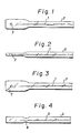
- FIGS 1 and 2 show a first embodiment of indwelling thermosensor according to this invention.
- a thermocouple 1 is disposed within a generally cylindrical tube 2 made of fluoro resin.
- the cylindrical tube 2 is deformed at its left end to have a flat configuration as shown in the drawings.
- the tube 2 is formed with an aperture 3 in the flattened part.
- a body fluid or the like might enter the tube 2 through the aperture 3.
- the tube end is therefore sealed, as above, for preventing this.
- the forming into a flat shape has the merit of facilitating the formation of the aperture 3 and also easy passage of a wiring member, for example, a thread, passed through the aperture 3.
- the size for the flat portion may be selected depending on the diameter of the aperture 3 and the outer diameter of the tube 2.
- the flat portion is fabricated by heat sealing the top end of the tube 2 and, at the same time, crushing it between flat plates into a flat shape as described above and then forming an aperture at the flattened portion.
- the size of the aperture 3 may optionally be selected depending on the outer diameter and the wall thickness of the tube 2 and it ranges usually from 0.5 mm to 3 mm and, preferably, from 1 to 2 mm for cases where the tube is to be fixed by a thread.
- One of the ends of the thermocouple is connected to a temperature indicator by way of a connector or the like.
- thermosensitive portion is secured, for instance, by a surgical operation, to the outer wall of the oesophagus and held in position by the thread passing through the hole 3 while a lead wire continuous with the thermosensitive portion is exposed through the armpit to the surface of the body. Then, after fixing the lead wire to the body surface by means of a known method such as adhesive tapes or the like, the lead wire is connected to a temperature indicator for temperature measurement every time hyperthermia therapy is applied.
- a slit 7 which connects the aperture 3 and the outside of the indwelling sensor may further be provided as shown in Figure 3.
- FIG. 4 shows a second embodiment according to this invention.
- a narrowed portion 6 is formed at the left end of a tube 4.
- the portion 6 is formed such that its diameter is smaller than the diameter of the adjacent portions of the heat shrinking fluoro resin tube.
- the tube can be made for instance by inserting round bars each with 2 mm outer diameter and 10 mm length into a heat shrinking fluoro resin tube with 2.5 mm outer diameter while keeping the end of the rods 3 mm apart from each other and then heating them to form the pinched portion 6 as shown in Figure 4.
- the outer diameter at the pinched portion is 1.8 mm.
- a high resistance reed thermistor 5 is embedded in the tube, which is a protection tube, to complete the thermosensor.
- thermosensor In the actual use, the thermosensor is fixed by binding the pinched portion with a thread which is then secured to the body. Since the fluoro resin is hard and the thread or wire member does not bite into the tube surface, there may occasionally be a clearance in the recessed portion which allows a slight displacement, but the thread does not slip away from the recess.
- the protection tube is entirely or partially made of rubbery elastic material, for example, a silicone rubber.
- An engaging portion may be prepared by binding the tube with a stitching thread.
- the rubbery elastic material requires a thickness of more than 0.3 mm.
- an indwelling thermosensor can be prepared by passing a linear thermocouple of 0.1 mm diameter appended longitudinally with carbon fibres having, for example, 10 000 strands of filaments while applying a coating of silicone adhesives through a silicone tube of 2 mm outer diameter and 1 mm inner diameter.
- the thermosensor is tied at a position 10 mm from the top end with surgical threads and 500 g of force is applied, the positional displacement is less than 0.5 mm.
- an insulation powder such as MgO may be used to fill the protection tube and the top end may be exposed.
- the pinched portion 6 need. not necessarily be formed only at one portion.
- a bellows-like engagement involving several pinched portions may be employed.
- the shape of the pinched portions and the size of the aperture may be modified depending on the purposes or the application uses.
- thermoelectromotive force As the temperature detecting element, a platinum or other resistor member or a thermistor that utilizes the change in the electrical resistance, or an alumel-chromel thermocouple utilizing the thermoelectromotive force is preferred.
- a platinum or other resistor member or a thermistor that utilizes the change in the electrical resistance, or an alumel-chromel thermocouple utilizing the thermoelectromotive force is preferred.
- fluoro resin, silicon resin or the like which are harmless when the tube is caused to stay inside living tissue, are preferred.
- the protection tube has an engaging portion retained with respect to the living tissue by means of a thread or wire member, for example a stitching thread, there is no particular restriction on the shape and the material of the thread employed.
- stitching threads mainly composed of collagen, polyvinyl alcohol or the like are preferably used.
- the engaging portion is provided at at least one position at the top end or any other desired part of the tube.
- the configuration may, for instance, be an aperture, narrowing, or bellows.
- an indwelling thermosensor comprising a temperature detecting element and a protection tube for protecting the temperature detecting element
- the protection tube is so constituted that, even if a part for measuring the temperature is situated deep inside a living body, a thread or wire member joined to the protection tube for securing the part of the protection tube where the temperature detection element is disposed to a desired position is not displaced from the protection tube. Insertion of the thermosensor, setting thereof to the desired position for measuring the temperature, and securing of the tube wall at the desired position can be carried out with ease, whereby the temperature at the desired position can be detected reliably.
Landscapes
- Physics & Mathematics (AREA)
- General Physics & Mathematics (AREA)
- Measuring Temperature Or Quantity Of Heat (AREA)
- External Artificial Organs (AREA)
- Materials For Medical Uses (AREA)
Applications Claiming Priority (2)
| Application Number | Priority Date | Filing Date | Title |
|---|---|---|---|
| JP59134910A JPS6114530A (ja) | 1984-06-29 | 1984-06-29 | 留置測温センサ |
| JP134910/84 | 1984-06-29 |
Publications (2)
| Publication Number | Publication Date |
|---|---|
| EP0167262A2 true EP0167262A2 (de) | 1986-01-08 |
| EP0167262A3 EP0167262A3 (de) | 1987-03-18 |
Family
ID=15139383
Family Applications (1)
| Application Number | Title | Priority Date | Filing Date |
|---|---|---|---|
| EP85303675A Withdrawn EP0167262A3 (de) | 1984-06-29 | 1985-05-24 | Eingehüllter Thermosensor |
Country Status (3)
| Country | Link |
|---|---|
| EP (1) | EP0167262A3 (de) |
| JP (1) | JPS6114530A (de) |
| DK (1) | DK252985A (de) |
Cited By (1)
| Publication number | Priority date | Publication date | Assignee | Title |
|---|---|---|---|---|
| WO2003078949A1 (en) * | 2002-03-16 | 2003-09-25 | University Of Bristol | Thermometer |
Family Cites Families (4)
| Publication number | Priority date | Publication date | Assignee | Title |
|---|---|---|---|---|
| US2915175A (en) * | 1956-07-16 | 1959-12-01 | Diamant Marcus | Protective sheath for fever thermometers |
| US3835990A (en) * | 1972-10-25 | 1974-09-17 | Bio Medical Sciences Inc | Thermometer packaging |
| US4164285A (en) * | 1978-04-26 | 1979-08-14 | Arbrook, Inc. | Thermometer sheath |
| US4369795A (en) * | 1980-06-17 | 1983-01-25 | Bicher James I | Implantable microthermocouple member |
-
1984
- 1984-06-29 JP JP59134910A patent/JPS6114530A/ja active Pending
-
1985
- 1985-05-24 EP EP85303675A patent/EP0167262A3/de not_active Withdrawn
- 1985-06-04 DK DK252985A patent/DK252985A/da not_active Application Discontinuation
Cited By (2)
| Publication number | Priority date | Publication date | Assignee | Title |
|---|---|---|---|---|
| WO2003078949A1 (en) * | 2002-03-16 | 2003-09-25 | University Of Bristol | Thermometer |
| US8684944B2 (en) | 2002-03-16 | 2014-04-01 | University Of Bristol | Thermometer |
Also Published As
| Publication number | Publication date |
|---|---|
| EP0167262A3 (de) | 1987-03-18 |
| JPS6114530A (ja) | 1986-01-22 |
| DK252985D0 (da) | 1985-06-04 |
| DK252985A (da) | 1985-12-30 |
Similar Documents
| Publication | Publication Date | Title |
|---|---|---|
| US3531992A (en) | Expendable tympanic membrane thermometer | |
| US3500280A (en) | Temperature sensing probe | |
| EP0171959B1 (de) | Elektrode zur Messung der Konzentration von Wasserstoffionen | |
| EP0588631B1 (de) | Klinisches Thermometer | |
| CA1132367A (en) | Clinical thermometer with thermo-couple probe | |
| US6979122B2 (en) | Deflectable probe and thermometer | |
| JP2003024447A (ja) | 生物の体内に挿入可能な測定装置 | |
| US5534013A (en) | Pacifier thermometer | |
| KR19980701955A (ko) | 밀봉 장치 | |
| EP2978279A1 (de) | Elektrisches heizelement und verfahren zur herstellung des elektrischen heizelements | |
| US3513432A (en) | Shielded thermoelectric transducer/conductor construction | |
| EP0167262A2 (de) | Eingehüllter Thermosensor | |
| US2981251A (en) | Inflatable blood pressure cuff | |
| US2509825A (en) | Heat sensitive device | |
| JPH0797049B2 (ja) | 温度センサの製造方法 | |
| CN85104234A (zh) | 内装式温度传感器 | |
| US3834226A (en) | Disposable temperature indicator | |
| BR0105778A (pt) | Método para a fabricação de uma sonda de temperatura vedada e sonda assim fabricada | |
| EP3708981B1 (de) | Vorrichtung zum halten eines thermometers für den klinischen gebrauch während des schüttelns | |
| US5399019A (en) | Method and apparatus for measuring temperatures in fabrics and flexible thermal insulations | |
| GB2276766A (en) | Heat and compression detection cable | |
| JPH0640829U (ja) | 可撓性温度検出装置 | |
| JP3333875B2 (ja) | 温度計測素子、およびこれを用いる温度計測方法 | |
| KOURTIDES | Method and apparatus for measuring temperatures in fabrics and flexible thermal insulations(Patent) | |
| US4728369A (en) | Thermocouple probes |
Legal Events
| Date | Code | Title | Description |
|---|---|---|---|
| PUAI | Public reference made under article 153(3) epc to a published international application that has entered the european phase |
Free format text: ORIGINAL CODE: 0009012 |
|
| AK | Designated contracting states |
Designated state(s): DE FR GB IT |
|
| PUAL | Search report despatched |
Free format text: ORIGINAL CODE: 0009013 |
|
| AK | Designated contracting states |
Kind code of ref document: A3 Designated state(s): DE FR GB IT |
|
| STAA | Information on the status of an ep patent application or granted ep patent |
Free format text: STATUS: THE APPLICATION IS DEEMED TO BE WITHDRAWN |
|
| 18D | Application deemed to be withdrawn |
Effective date: 19870921 |
|
| RIN1 | Information on inventor provided before grant (corrected) |
Inventor name: MATSUFUJI, HIDEMASA Inventor name: KAWAI, YOSHIO Inventor name: SOGAWA, AKIRA Inventor name: KAI, HIDENOBU Inventor name: SHIRAKAMI, TOSHIHARU |