EP0167224B1 - Tyre building apparatus - Google Patents
Tyre building apparatus Download PDFInfo
- Publication number
- EP0167224B1 EP0167224B1 EP85302617A EP85302617A EP0167224B1 EP 0167224 B1 EP0167224 B1 EP 0167224B1 EP 85302617 A EP85302617 A EP 85302617A EP 85302617 A EP85302617 A EP 85302617A EP 0167224 B1 EP0167224 B1 EP 0167224B1
- Authority
- EP
- European Patent Office
- Prior art keywords
- turret
- tyre
- formers
- former
- axes
- Prior art date
- Legal status (The legal status is an assumption and is not a legal conclusion. Google has not performed a legal analysis and makes no representation as to the accuracy of the status listed.)
- Expired - Lifetime
Links
Images
Classifications
-
- B—PERFORMING OPERATIONS; TRANSPORTING
- B29—WORKING OF PLASTICS; WORKING OF SUBSTANCES IN A PLASTIC STATE IN GENERAL
- B29D—PRODUCING PARTICULAR ARTICLES FROM PLASTICS OR FROM SUBSTANCES IN A PLASTIC STATE
- B29D30/00—Producing pneumatic or solid tyres or parts thereof
- B29D30/0016—Handling tyres or parts thereof, e.g. supplying, storing, conveying
-
- B—PERFORMING OPERATIONS; TRANSPORTING
- B29—WORKING OF PLASTICS; WORKING OF SUBSTANCES IN A PLASTIC STATE IN GENERAL
- B29D—PRODUCING PARTICULAR ARTICLES FROM PLASTICS OR FROM SUBSTANCES IN A PLASTIC STATE
- B29D30/00—Producing pneumatic or solid tyres or parts thereof
- B29D30/005—General arrangement or lay-out of plants for the processing of tyres or parts thereof
-
- B—PERFORMING OPERATIONS; TRANSPORTING
- B29—WORKING OF PLASTICS; WORKING OF SUBSTANCES IN A PLASTIC STATE IN GENERAL
- B29D—PRODUCING PARTICULAR ARTICLES FROM PLASTICS OR FROM SUBSTANCES IN A PLASTIC STATE
- B29D30/00—Producing pneumatic or solid tyres or parts thereof
- B29D30/06—Pneumatic tyres or parts thereof (e.g. produced by casting, moulding, compression moulding, injection moulding, centrifugal casting)
- B29D30/08—Building tyres
- B29D30/20—Building tyres by the flat-tyre method, i.e. building on cylindrical drums
- B29D2030/206—A plurality of building drums being mounted on a fixture or supporting device, e.g. turret or turntable
-
- B—PERFORMING OPERATIONS; TRANSPORTING
- B29—WORKING OF PLASTICS; WORKING OF SUBSTANCES IN A PLASTIC STATE IN GENERAL
- B29D—PRODUCING PARTICULAR ARTICLES FROM PLASTICS OR FROM SUBSTANCES IN A PLASTIC STATE
- B29D30/00—Producing pneumatic or solid tyres or parts thereof
- B29D30/06—Pneumatic tyres or parts thereof (e.g. produced by casting, moulding, compression moulding, injection moulding, centrifugal casting)
- B29D30/08—Building tyres
- B29D30/20—Building tyres by the flat-tyre method, i.e. building on cylindrical drums
- B29D2030/208—Building tyres by the flat-tyre method, i.e. building on cylindrical drums the drum supporting device being rotatable around a vertical axis
Definitions
- This invention relates to improvements in the manufacture of pneumatic tyres, in particular to an apparatus according to the preamble of claim 1. Particularly where such manufacture is carried out by automatic machinery, it is necessary for tyre building material to be applied to tyre building formers, or to formers for the manufacture of tyre components, and subsequently for partly-built tyres or tyre components to be transferred to other formers for subsequent stages of the manufacturing process.
- a tyre building apparatus comprising:-
- the transfer means comprises three said carrier means on the third rotatable turret.
- At least one ancillary apparatus is arranged peripherally of said second turret and in alignment with one of said stations occupied by said second formers, and the second formers on the second turret are capable of movement axially with respect to their own axes and radially with respect to the second turret, so as to move into operative alignment with the ancillary apparatus.
- the components may be passed from one turret to another through a number of manufacturing stages of the tyre building apparatus.
- the apparatus shown in the drawing comprises rotatable turrets 10, 11, 12 and 13.
- An ancillary apparatus 14 is located adjacent the turret 12 for the supply of carcass ply material.
- the turret 10 comprises five formers 20 rotatably mounted on drive units 21 carried on a turntable 22 which is rotatable about a vertical axis to bring the formers 20 successively into a turret station 25 adjacent the second rotatable turret 11.
- the formers 20 are movable along the direction of their axes, i.e. radially with respect to the axis of the turret 10 so that each former 20 when in the turret station 25 may be moved into a position coaxially within a carrier sleeve 30 mounted on the second rotatable turret 11.
- Sockets 31 are provided at the ends of the formers 20 for engagement with suitable spigots (not shown) located within the sleeves 30 in order to centre and axially locate the formers 20 within the sleeves 30.
- the turret 10 forms part of the apparatus for making inner liners described in greater detail in our co-pending Application No. 8332509 (WAB 928).
- WAB 928 unvulcanised rubber strip from a small calender is wound helically around each former 20 to form a continuous layer on its surface to provide an inner lining for the tyre to be built.
- the carrier sleeve 30 is arranged to receive the completed liner on its inner periphery, transfer being effected by expansion of the former 20 (which may be of the inflatable type) and vacuum gripping means may be provided on the interior of the sleeve 30 to enable the liner to be retained in position in the sleeve after it has been transferred.
- the former 20 which may be of the inflatable type
- vacuum gripping means may be provided on the interior of the sleeve 30 to enable the liner to be retained in position in the sleeve after it has been transferred.
- the former 20 is retracted to enable rotation of the respective turrets 10 and 11 to take place and thus bring another former 20 into position adjacent another sleeve 30 for the next transfer operation.
- the rotation of the turret 11 brings a sleeve 30, containing an inner liner, into the position shown at 33 where it is aligned with a former 35 carried on the rotatable turret 12.
- the former 35 is axially movable to a position within the carrier sleeve in a similar manner to the former 20, but in this case the subsequent procedure is reversed, the former 35 being expansible, when in an accurately located coaxial position within the sleeve 33, to pick up the inner liner and transfer it to the periphery of the former 35.
- the former 35 On completion of the transfer of the liner to the former 35, the former 35 is retracted and the respective turrets are again rotated to index the formers and sleeves to a new position in which the former 35 now occupies the position shown at 38, where it lies adjacent ancillary apparatus 14 for the supply of carcass ply material in the form of sheets 41 supported on a table 43, this apparatus being described in greater detail in our co-pending Application No. 8403494 (WAB 1009).
- the former 35 In order to effect transfer of the carcass ply material sheet 41, the former 35 is axially moved into the position indicated (partly broken away) at 44, the axial position of the former again being accurately controlled, and the former is rotated to enable the ply material to be wrapped around it. On completion of this operation the former 32 is again retracted to the position shown at 38 and the turrets are again indexed, the former 35 carrying the inner liner and carcass ply material then being brought into the position shown at 48 where it lies adjacent the fourth rotatable turret 13.
- the turret 13 carries three frames 50 (only one of which is shown in the drawing), which each support a "bead tube" 51 described in more detail in our copending Application No. 8328737 (WAB 925).
- a pair of bead wire assemblies have been applied to the ends of the bead tube 51, and as shown in the drawing the bead tube is ready to receive the former 35 by axial movement from the position 48 to a position coaxially within the bead tube 51.
- the former 35 is expanded to bring the carcass ply material into engagement with the bead wire assemblies and the material is turned around the bead wire assemblies by further expansion of the axially outboard ends of the former relative to the bead tube.
- the former 35 is then contracted and removed from the bead tube, leaving the partly-built tyre carcass within the bead tube for subsequent transfer to a shaping former, and the former 35 is retracted to the position shown at 48.
- the apparatus illustrated is of course part of a larger assembly of machinery for the automatic manufacture of pneumatic tyres, but it is believed that the above description contains sufficient examples of the principles of operation of apparatus in accordance with the invention to enable the invention to be clearly understood.
- the advantages flowing from the use of apparatus as described include great accuracy in positioning formers and component carriers to enable a tyre carcass to be accurately and rapidly built.
- the apparatus is particularly compact and well suited to automatic operation.
- apparatus in accordance with the invention may alternatively comprise a turret rotatable about a horizontal axis.
- the former may be supported on the turret with its axis disposed radially to the turret axis so that it is movable axially with respect to its own axis and radially with respect to the turret axis, or, in order to preserve a horizontal alignment of the former axis in all angular positions of the turret it may be supported on the turret with its axis parallel to the turret axis. In the latter case, movement of the former into and out of an associated component carrier may not be in a radial direction relative to the axis of the turret, but may take place in a direction transverse to that radial direction.
Description
- This invention relates to improvements in the manufacture of pneumatic tyres, in particular to an apparatus according to the preamble of claim 1. Particularly where such manufacture is carried out by automatic machinery, it is necessary for tyre building material to be applied to tyre building formers, or to formers for the manufacture of tyre components, and subsequently for partly-built tyres or tyre components to be transferred to other formers for subsequent stages of the manufacturing process.
- The design of manufacturing plant for pneumatic tyres by automatic assembly techniques presents problems in arranging for accurate and rapid transfer of components and partly-built tyres from one stage to the next. In US-A-2407152, upon which the preamble of claim 1 is based, there is disclosed tyre building apparatus including three rotatable turrets each having a plurality of tyre building formers thereon. Tyre component sub-assembles are made on each of the two outer turrets and are transferred to the third inner turret located therebetween. The transfer means is accomplished by a linear movement between the two turrets. In US-A-3532577 there is disclosed another type of linear transfer means which can be moved to transfer between different sets of stations.
- It is an object of the present invention to provide an improved transfer means for achieving a compact factory layout.
- According to the present invention, there is provided a tyre building apparatus comprising:-
- a first rotatable turret having a plurality of first formers thereon which are rotatably displaceable between a number of stations,
- a second rotatable turret having a plurality of second formers which are rotatably displaceable between a number of stations,
- and a transfer means for transfer of components from one station on the first turret to a second station on the second turret,
characterised in that the transfer means comprises a third rotatable turret with at least two carrier means thereon, each of tubular form for supporting a cylindrical tyre component within the respective carrier means, said carrier means being rotatably displaceable between fixed positions and arranged so that said two carrier means are simultaneously in alignment one with said one of the stations of the first turret, and the other with one of said second stations of the second turret. - Preferably the transfer means comprises three said carrier means on the third rotatable turret.
- Conveniently at least one ancillary apparatus is arranged peripherally of said second turret and in alignment with one of said stations occupied by said second formers, and the second formers on the second turret are capable of movement axially with respect to their own axes and radially with respect to the second turret, so as to move into operative alignment with the ancillary apparatus.
- By having a series of turrets the components may be passed from one turret to another through a number of manufacturing stages of the tyre building apparatus.
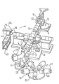
- One embodiment of the invention will now be described, by way of example, with reference to the accompanying drawing which is a diagrammatic perspective view showing tyre building apparatus incorporating four adjoining rotatable turrets.
- The apparatus shown in the drawing comprises
rotatable turrets turret 12 for the supply of carcass ply material. - The
turret 10 comprises fiveformers 20 rotatably mounted ondrive units 21 carried on aturntable 22 which is rotatable about a vertical axis to bring theformers 20 successively into aturret station 25 adjacent the secondrotatable turret 11. Theformers 20 are movable along the direction of their axes, i.e. radially with respect to the axis of theturret 10 so that each former 20 when in theturret station 25 may be moved into a position coaxially within acarrier sleeve 30 mounted on the secondrotatable turret 11.Sockets 31 are provided at the ends of theformers 20 for engagement with suitable spigots (not shown) located within thesleeves 30 in order to centre and axially locate theformers 20 within thesleeves 30. - In the manufacture of a pneumatic tyre, the
turret 10 forms part of the apparatus for making inner liners described in greater detail in our co-pending Application No. 8332509 (WAB 928). In this apparatus unvulcanised rubber strip from a small calender is wound helically around each former 20 to form a continuous layer on its surface to provide an inner lining for the tyre to be built. At thetransfer station 25, thecarrier sleeve 30 is arranged to receive the completed liner on its inner periphery, transfer being effected by expansion of the former 20 (which may be of the inflatable type) and vacuum gripping means may be provided on the interior of thesleeve 30 to enable the liner to be retained in position in the sleeve after it has been transferred. - Following transfer of a liner from the
turret 10 to theturret 11, the former 20 is retracted to enable rotation of therespective turrets sleeve 30 for the next transfer operation. Simultaneously, the rotation of theturret 11 brings asleeve 30, containing an inner liner, into the position shown at 33 where it is aligned with a former 35 carried on therotatable turret 12. The former 35 is axially movable to a position within the carrier sleeve in a similar manner to the former 20, but in this case the subsequent procedure is reversed, the former 35 being expansible, when in an accurately located coaxial position within thesleeve 33, to pick up the inner liner and transfer it to the periphery of the former 35. - On completion of the transfer of the liner to the former 35, the former 35 is retracted and the respective turrets are again rotated to index the formers and sleeves to a new position in which the former 35 now occupies the position shown at 38, where it lies adjacent ancillary apparatus 14 for the supply of carcass ply material in the form of sheets 41 supported on a table 43, this apparatus being described in greater detail in our co-pending Application No. 8403494 (WAB 1009).
- In order to effect transfer of the carcass ply material sheet 41, the former 35 is axially moved into the position indicated (partly broken away) at 44, the axial position of the former again being accurately controlled, and the former is rotated to enable the ply material to be wrapped around it. On completion of this operation the former 32 is again retracted to the position shown at 38 and the turrets are again indexed, the former 35 carrying the inner liner and carcass ply material then being brought into the position shown at 48 where it lies adjacent the fourth
rotatable turret 13. - The
turret 13 carries three frames 50 (only one of which is shown in the drawing), which each support a "bead tube" 51 described in more detail in our copending Application No. 8328737 (WAB 925). In another station of theturret 13, a pair of bead wire assemblies have been applied to the ends of thebead tube 51, and as shown in the drawing the bead tube is ready to receive the former 35 by axial movement from theposition 48 to a position coaxially within thebead tube 51. In this position, the former 35 is expanded to bring the carcass ply material into engagement with the bead wire assemblies and the material is turned around the bead wire assemblies by further expansion of the axially outboard ends of the former relative to the bead tube. The former 35 is then contracted and removed from the bead tube, leaving the partly-built tyre carcass within the bead tube for subsequent transfer to a shaping former, and the former 35 is retracted to the position shown at 48. - The apparatus illustrated is of course part of a larger assembly of machinery for the automatic manufacture of pneumatic tyres, but it is believed that the above description contains sufficient examples of the principles of operation of apparatus in accordance with the invention to enable the invention to be clearly understood. The advantages flowing from the use of apparatus as described include great accuracy in positioning formers and component carriers to enable a tyre carcass to be accurately and rapidly built. The apparatus is particularly compact and well suited to automatic operation.
- While in the embdiment described above the axis of rotation of each turret is vertical, apparatus in accordance with the invention may alternatively comprise a turret rotatable about a horizontal axis.
- As in the previously described embodiment, the former may be supported on the turret with its axis disposed radially to the turret axis so that it is movable axially with respect to its own axis and radially with respect to the turret axis, or, in order to preserve a horizontal alignment of the former axis in all angular positions of the turret it may be supported on the turret with its axis parallel to the turret axis. In the latter case, movement of the former into and out of an associated component carrier may not be in a radial direction relative to the axis of the turret, but may take place in a direction transverse to that radial direction.
Claims (9)
Applications Claiming Priority (2)
| Application Number | Priority Date | Filing Date | Title |
|---|---|---|---|
| GB8411820 | 1984-05-09 | ||
| GB848411820A GB8411820D0 (en) | 1984-05-09 | 1984-05-09 | Manufacture |
Publications (3)
| Publication Number | Publication Date |
|---|---|
| EP0167224A2 EP0167224A2 (en) | 1986-01-08 |
| EP0167224A3 EP0167224A3 (en) | 1988-04-27 |
| EP0167224B1 true EP0167224B1 (en) | 1990-03-14 |
Family
ID=10560665
Family Applications (1)
| Application Number | Title | Priority Date | Filing Date |
|---|---|---|---|
| EP85302617A Expired - Lifetime EP0167224B1 (en) | 1984-05-09 | 1985-04-15 | Tyre building apparatus |
Country Status (9)
| Country | Link |
|---|---|
| US (1) | US4732640A (en) |
| EP (1) | EP0167224B1 (en) |
| JP (1) | JPS60245542A (en) |
| AU (1) | AU577585B2 (en) |
| BR (1) | BR8502173A (en) |
| DE (1) | DE3576472D1 (en) |
| GB (2) | GB8411820D0 (en) |
| MY (1) | MY103098A (en) |
| ZA (1) | ZA853084B (en) |
Families Citing this family (26)
| Publication number | Priority date | Publication date | Assignee | Title |
|---|---|---|---|---|
| IT1189648B (en) * | 1986-04-08 | 1988-02-04 | Firestone Int Dev Spa | DOUBLE SWIVEL DRUM UNIT FOR THE PRODUCTION OF TIRES |
| GB8619617D0 (en) * | 1986-08-12 | 1986-09-24 | Apsley Metals Ltd | Tyre building machinery |
| DE68907734T2 (en) * | 1988-01-25 | 1993-12-23 | Bridgestone Corp | Device for transferring a cylindrical component and tire building machine having such a device. |
| EP0414554A3 (en) * | 1989-08-24 | 1992-10-28 | Bridgestone Corporation | Tire building method and apparatus |
| CA2038138C (en) * | 1990-10-12 | 2002-01-01 | Kenneth Dean Conger | Tire building apparatus and method |
| US5582666A (en) * | 1994-04-11 | 1996-12-10 | Mitsubishi Jukogyo Kabushiki Kaisha | Method of forming a radial tire |
| WO1998012043A1 (en) * | 1996-09-18 | 1998-03-26 | The Goodyear Tire And Rubber Company | Method and apparatus for simultaneously assembling a plurality of tyres |
| US6139668A (en) * | 1996-09-18 | 2000-10-31 | The Goodyear Tire & Rubber Company | Method and apparatus for simultaneously assembling a plurality of tires |
| JP2002103473A (en) * | 2000-10-03 | 2002-04-09 | Yokohama Rubber Co Ltd:The | Tire molding drum apparatus |
| ITVR20010060A1 (en) * | 2001-05-18 | 2002-11-18 | Marangoni Meccanica | RAW TIRES MANUFACTURING PROCEDURE. |
| FR2839005A1 (en) * | 2002-04-25 | 2003-10-31 | Michelin Soc Tech | PROCESS FOR THE HANDLING OF TAPE PRODUCTS FOR THEIR USE IN THE MANUFACTURE OF A TIRE COVER |
| US20050051256A1 (en) * | 2003-09-09 | 2005-03-10 | Yovichin Albert James | Method and apparatus for building and transferring a tread belt structure |
| EP1827807B2 (en) * | 2004-12-16 | 2017-08-30 | Pirelli Tyre S.p.A. | Method and plant for manufacturing tyres for vehicle wheels |
| JP2008524019A (en) * | 2004-12-16 | 2008-07-10 | ピレリ・タイヤ・ソチエタ・ペル・アツィオーニ | Method and plant for producing tires for vehicle wheels |
| US20080314504A1 (en) * | 2004-12-16 | 2008-12-25 | Gianni Mancini | Method and Plant for Manufacturing Tyres for Vehicle Wheels |
| US20090314436A1 (en) * | 2005-12-07 | 2009-12-24 | Toyo Tire & Rubber Co., Ltd. | Bead supply system in tire building process |
| ATE533615T1 (en) * | 2008-04-18 | 2011-12-15 | Pirelli | METHOD AND DEVICE FOR MOUNTING TIRES |
| JP6068980B2 (en) * | 2009-12-21 | 2017-01-25 | ピレリ・タイヤ・ソチエタ・ペル・アツィオーニ | Process and plant for building tires |
| JP5813306B2 (en) * | 2010-11-02 | 2015-11-17 | 株式会社ブリヂストン | Tire bead supply device |
| JP5431442B2 (en) * | 2011-12-02 | 2014-03-05 | ピレリ・タイヤ・ソチエタ・ペル・アツィオーニ | Method and plant for producing tires for vehicle wheels |
| JP5792605B2 (en) * | 2011-12-02 | 2015-10-14 | ピレリ・タイヤ・ソチエタ・ペル・アツィオーニ | Method and plant for producing tires for vehicle wheels |
| US20140027063A1 (en) * | 2012-07-25 | 2014-01-30 | Frederic Marie Bernard Marechal | Tire building machine with extendable drums |
| US20140166189A1 (en) * | 2012-12-18 | 2014-06-19 | The Goodyear Tire & Rubber Company | Method and apparatus for building a tire |
| MX2017003915A (en) | 2014-11-14 | 2017-06-26 | Pirelli | Process and plant for building tyres. |
| WO2016108098A1 (en) | 2014-12-29 | 2016-07-07 | Pirelli Tyre S.P.A. | Process and plant for building tyres for vehicle wheels |
| IT201600119949A1 (en) * | 2016-11-28 | 2018-05-28 | Intereuropean Srl | APPARATUS AND METHOD FOR THE PRODUCTION OF TIRES |
Family Cites Families (12)
| Publication number | Priority date | Publication date | Assignee | Title |
|---|---|---|---|---|
| US2407152A (en) * | 1943-01-30 | 1946-09-03 | Wingfoot Corp | Method for building pneumatic tires |
| US2818907A (en) * | 1955-05-26 | 1958-01-07 | Goodrich Co B F | Tire building machinery |
| BE637479A (en) * | 1962-09-18 | |||
| GB1149722A (en) * | 1964-03-20 | 1969-04-23 | Dunlop Co Ltd | Improvements in and relating to tyre building apparatus |
| DE1579129C3 (en) * | 1964-10-03 | 1974-11-21 | Continental Gummi-Werke Ag, 3000 Hannover | Radial tire building machine |
| JPS5143070B2 (en) * | 1972-05-31 | 1976-11-19 | ||
| US3888720A (en) * | 1973-02-05 | 1975-06-10 | Uniroyal Inc | Tire building machine having a variable diameter tire building drum |
| DE2409586B2 (en) * | 1974-02-28 | 1976-12-09 | Zusatz in: 25 05 486 Continental Gummi-Werke AG, 3000 Hannover | DEVICE FOR TRANSFERRING A CARCASS COVERED WITH CORE RINGS FOR BLANK TIRE TIRES |
| US4134783A (en) * | 1976-06-16 | 1979-01-16 | The Goodyear Tire & Rubber Company | Tire building system |
| US4197155A (en) * | 1978-08-04 | 1980-04-08 | The Goodyear Tire & Rubber Company | Tire building drum having three orthogonally oriented tire building drums |
| US4268330A (en) * | 1978-12-29 | 1981-05-19 | Bridgestone Tire Company Limited | Green tire building process and apparatus |
| US4440290A (en) * | 1981-04-02 | 1984-04-03 | Sherwood Tool, Incorporated | Receptacle forming apparatus having split receiver |
-
1984
- 1984-05-09 GB GB848411820A patent/GB8411820D0/en active Pending
-
1985
- 1985-04-15 EP EP85302617A patent/EP0167224B1/en not_active Expired - Lifetime
- 1985-04-15 DE DE8585302617T patent/DE3576472D1/en not_active Expired - Fee Related
- 1985-04-15 GB GB08509567A patent/GB2158400B/en not_active Expired
- 1985-04-19 US US06/724,888 patent/US4732640A/en not_active Expired - Lifetime
- 1985-04-25 ZA ZA853084A patent/ZA853084B/en unknown
- 1985-05-02 AU AU41899/85A patent/AU577585B2/en not_active Ceased
- 1985-05-09 JP JP60098879A patent/JPS60245542A/en active Granted
- 1985-07-07 BR BR8502173A patent/BR8502173A/en not_active IP Right Cessation
-
1988
- 1988-06-10 MY MYPI88000640A patent/MY103098A/en unknown
Also Published As
| Publication number | Publication date |
|---|---|
| ZA853084B (en) | 1986-02-26 |
| US4732640A (en) | 1988-03-22 |
| BR8502173A (en) | 1986-01-07 |
| EP0167224A3 (en) | 1988-04-27 |
| GB2158400B (en) | 1988-05-11 |
| GB8509567D0 (en) | 1985-05-22 |
| EP0167224A2 (en) | 1986-01-08 |
| JPH0414621B2 (en) | 1992-03-13 |
| GB8411820D0 (en) | 1984-06-13 |
| AU4189985A (en) | 1985-11-14 |
| MY103098A (en) | 1993-04-30 |
| DE3576472D1 (en) | 1990-04-19 |
| JPS60245542A (en) | 1985-12-05 |
| AU577585B2 (en) | 1988-09-29 |
| GB2158400A (en) | 1985-11-13 |
Similar Documents
| Publication | Publication Date | Title |
|---|---|---|
| EP0167224B1 (en) | Tyre building apparatus | |
| EP0105048B1 (en) | Arrangement for constructing tyres | |
| EP0613767B1 (en) | Method of forming a green tyre | |
| US5354404A (en) | Control for integrated tire building system | |
| US20080190548A1 (en) | Method and Device for Positioning Bead Wires | |
| EP0069047A2 (en) | Apparatus for manufacturing a radial tire | |
| US3865670A (en) | Breaker-tread assembly transfer ring size changing mechanism | |
| EP1497106B1 (en) | Method and plant for the manufacture of green tyres | |
| CN108698347B (en) | Process and plant for building tyres | |
| JPS5946782B2 (en) | Tire manufacturing method and equipment | |
| EP0747207A2 (en) | Tire building machine | |
| US4990211A (en) | Tire building apparatus including a turret for conveying a transfer box | |
| EP0719632B1 (en) | Single-stage tire forming system | |
| US6983782B2 (en) | Assembly drum for the manufacture of tires | |
| EP1127683A2 (en) | Tyre building drum for the manufacture of a folded tyre belt | |
| EP0278892B1 (en) | A tyre building former | |
| RU2343072C2 (en) | Unit for manufacturing uncured radial tyres and method for their manufacturing | |
| US3257255A (en) | Apparatus for building tires | |
| KR0171587B1 (en) | Tire building apparatus and method | |
| US3388024A (en) | Tire carcass building drum | |
| JPS59202838A (en) | Transfer apparatus of endless member of pneumatic tire | |
| KR102529535B1 (en) | Method and equipment for producing tires for wheels | |
| CA1204990A (en) | Manufacture of pneumatic tyres | |
| KR102521300B1 (en) | Method of manufacturing a belt assembly for a tire for a wheel | |
| GB1430286A (en) | Method and apparatus for manufacturing pipes |
Legal Events
| Date | Code | Title | Description |
|---|---|---|---|
| PUAI | Public reference made under article 153(3) epc to a published international application that has entered the european phase |
Free format text: ORIGINAL CODE: 0009012 |
|
| AK | Designated contracting states |
Designated state(s): DE FR IT LU NL |
|
| RAP1 | Party data changed (applicant data changed or rights of an application transferred) |
Owner name: W & A BATES LIMITED |
|
| PUAL | Search report despatched |
Free format text: ORIGINAL CODE: 0009013 |
|
| AK | Designated contracting states |
Kind code of ref document: A3 Designated state(s): DE FR IT LU NL |
|
| 17P | Request for examination filed |
Effective date: 19880526 |
|
| 17Q | First examination report despatched |
Effective date: 19890109 |
|
| GRAA | (expected) grant |
Free format text: ORIGINAL CODE: 0009210 |
|
| AK | Designated contracting states |
Kind code of ref document: B1 Designated state(s): DE FR IT LU NL |
|
| REF | Corresponds to: |
Ref document number: 3576472 Country of ref document: DE Date of ref document: 19900419 |
|
| ITF | It: translation for a ep patent filed |
Owner name: GUZZI E RAVIZZA S.R.L. |
|
| ET | Fr: translation filed | ||
| PLBE | No opposition filed within time limit |
Free format text: ORIGINAL CODE: 0009261 |
|
| STAA | Information on the status of an ep patent application or granted ep patent |
Free format text: STATUS: NO OPPOSITION FILED WITHIN TIME LIMIT |
|
| 26N | No opposition filed | ||
| PGFP | Annual fee paid to national office [announced via postgrant information from national office to epo] |
Ref country code: LU Payment date: 19910426 Year of fee payment: 7 Ref country code: FR Payment date: 19910426 Year of fee payment: 7 |
|
| ITTA | It: last paid annual fee | ||
| PGFP | Annual fee paid to national office [announced via postgrant information from national office to epo] |
Ref country code: NL Payment date: 19910430 Year of fee payment: 7 Ref country code: DE Payment date: 19910430 Year of fee payment: 7 |
|
| EPTA | Lu: last paid annual fee | ||
| PG25 | Lapsed in a contracting state [announced via postgrant information from national office to epo] |
Ref country code: LU Free format text: LAPSE BECAUSE OF NON-PAYMENT OF DUE FEES Effective date: 19920415 |
|
| PG25 | Lapsed in a contracting state [announced via postgrant information from national office to epo] |
Ref country code: NL Effective date: 19921101 |
|
| NLV4 | Nl: lapsed or anulled due to non-payment of the annual fee | ||
| PG25 | Lapsed in a contracting state [announced via postgrant information from national office to epo] |
Ref country code: FR Effective date: 19921230 |
|
| PG25 | Lapsed in a contracting state [announced via postgrant information from national office to epo] |
Ref country code: DE Effective date: 19930101 |
|
| REG | Reference to a national code |
Ref country code: FR Ref legal event code: ST |