EP0167169A2 - Kühlvorrichtung für eine Kraftfahrzeugmaschine - Google Patents
Kühlvorrichtung für eine Kraftfahrzeugmaschine Download PDFInfo
- Publication number
- EP0167169A2 EP0167169A2 EP85108305A EP85108305A EP0167169A2 EP 0167169 A2 EP0167169 A2 EP 0167169A2 EP 85108305 A EP85108305 A EP 85108305A EP 85108305 A EP85108305 A EP 85108305A EP 0167169 A2 EP0167169 A2 EP 0167169A2
- Authority
- EP
- European Patent Office
- Prior art keywords
- coolant
- radiator
- cooling circuit
- engine
- conduit
- Prior art date
- Legal status (The legal status is an assumption and is not a legal conclusion. Google has not performed a legal analysis and makes no representation as to the accuracy of the status listed.)
- Granted
Links
Images


Classifications
-
- F—MECHANICAL ENGINEERING; LIGHTING; HEATING; WEAPONS; BLASTING
- F01—MACHINES OR ENGINES IN GENERAL; ENGINE PLANTS IN GENERAL; STEAM ENGINES
- F01P—COOLING OF MACHINES OR ENGINES IN GENERAL; COOLING OF INTERNAL-COMBUSTION ENGINES
- F01P11/00—Component parts, details, or accessories not provided for in, or of interest apart from, groups F01P1/00 - F01P9/00
- F01P11/14—Indicating devices; Other safety devices
- F01P11/18—Indicating devices; Other safety devices concerning coolant pressure, coolant flow, or liquid-coolant level
-
- F—MECHANICAL ENGINEERING; LIGHTING; HEATING; WEAPONS; BLASTING
- F01—MACHINES OR ENGINES IN GENERAL; ENGINE PLANTS IN GENERAL; STEAM ENGINES
- F01P—COOLING OF MACHINES OR ENGINES IN GENERAL; COOLING OF INTERNAL-COMBUSTION ENGINES
- F01P11/00—Component parts, details, or accessories not provided for in, or of interest apart from, groups F01P1/00 - F01P9/00
- F01P11/02—Liquid-coolant filling, overflow, venting, or draining devices
-
- F—MECHANICAL ENGINEERING; LIGHTING; HEATING; WEAPONS; BLASTING
- F01—MACHINES OR ENGINES IN GENERAL; ENGINE PLANTS IN GENERAL; STEAM ENGINES
- F01P—COOLING OF MACHINES OR ENGINES IN GENERAL; COOLING OF INTERNAL-COMBUSTION ENGINES
- F01P3/00—Liquid cooling
- F01P3/22—Liquid cooling characterised by evaporation and condensation of coolant in closed cycles; characterised by the coolant reaching higher temperatures than normal atmospheric boiling-point
- F01P3/2285—Closed cycles with condenser and feed pump
-
- F—MECHANICAL ENGINEERING; LIGHTING; HEATING; WEAPONS; BLASTING
- F01—MACHINES OR ENGINES IN GENERAL; ENGINE PLANTS IN GENERAL; STEAM ENGINES
- F01P—COOLING OF MACHINES OR ENGINES IN GENERAL; COOLING OF INTERNAL-COMBUSTION ENGINES
- F01P7/00—Controlling of coolant flow
- F01P7/14—Controlling of coolant flow the coolant being liquid
- F01P7/16—Controlling of coolant flow the coolant being liquid by thermostatic control
Definitions
- the present invention relates generally to an evaporative type cooling system for an internal combustion engine wherein liquid coolant is permitted to boil and the vapor used as a vehicle for removing heat therefrom, and more specifically to such a system which enables rapid control of pressure prevailing in the cooling circuit thereof so as to offset any undesirable effects on temperature control that sudden changes in ambient conditions might have and which further prevents the intrusion of contaminating air and/or the like non-condensible matter.
- Fig. 2 shows an arrangement disclosed in Japanese Patent Application Second Provisional Publication Sho. 57-57608. This arrangement has attempted to vaporize a liquid coolant and use the gaseous form thereof as a vehicle for removing heat from the engine.
- the radiator 1 and the coolant jacket 2 are in constant and free communication via conduits 3, 4 whereby the coolant which condenses in the radiator 1 is returned to the coolant jacket 2 little by little under the influence of gravity.
- a gas permeable water shedding filter 5 is arranged as shown, to permit the entry of air into and out of the system.
- this filter permits gaseous coolant to readily escape from the system, inducing the need for frequent topping up of the coolant level.
- European Patent Application Provisional Publication No. 0 059 423 published on September 8, 1 982 discloses another arrangement wherein, liquid coolant in the coolant jacket of the engine, is not forcefully circulated therein and permitted to absorb heat to the point of boiling.
- the gaseous coolant thus generated is adiabatically compressed in a compressor so as to raise the temperature and pressure thereof and thereafter introduced into a heat exchanger (radiator). After condensing, the coolant is temporarily stored in a reservoir and recycled back into the coolant jacket via a flow control valve.
- the temperature of the radiator is controlled by selective energizations of the fan 9 which maintains a rate of condensation therein sufficient to provide a liquid seal at the bottom of the device. Condensate discharged from the radiator via the above mentioned liquid seal is collected in a small reservoir-like arrangement 10 and pumped back up to the separation tank via a small constantly energized pump 11.
- This arrangement while providing an arrangement via which air can be initially purged to some degree from the system tends to, due to the nature of the arrangement which permits said initial non-condensible matter to be forced out of the system, suffers from rapid loss of coolant when operated at relatively high altitudes. Further, once the engine cools air is relatively freely admitted back into the system. The provision of the bulky separation tank 6 also renders engine layout difficult.
- Japanese Patent Application First Provisional Publication No. sho. 56-32026 discloses an arrangement wherein the structure defining the cylinder head and cylinder liners are covered in a porous layer of ceramic material 12 and wherein coolant is sprayed into the cylinder block from shower-like arrangements 13 located above the cylinder heads 14.
- the interior of the coolant jacket defined within the engine proper is essentially filled with gaseous coolant during engine operation at which time liquid coolant sprayed onto the ceramic layers 12.
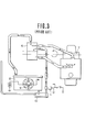
- Fig. 6 shows an arrangement which is disclosed in copending United States Patent Application Serial No. 663,911 filed on October 23, 1984 in the name of Hirano. The disclosure of this application is hereby incorporated by reference thereto.
- valves and conduits valves 13 4 , 15 2, 156 and 170 and conduits 150, 154 and 168 are required to execute the intended control thereof and further in that, even though provision is made to control the coolant boiling point by varying both the cooling effect provided by the fan 127 and the amount of coolant in the condensor or radiator 126, still the response to sudden changes in ambient conditions has been overly sluggish and thus has exhibited an unacceptable degree of oversensitivity to extenal influences.
- both the rate of heat exchange between the condenser (or radiator of the system) and the surrounding ambient atmospheric air and the amount of coolant in the cooling circuit are varied in a manner to change the pressure and therefore the boiling point of the coolant; and which particularly features an arrangment whereby the coolant is positively pumped to and from a reservoir which is maintained at atmospheric pressure into and out of a cooling circuit which is hermetically sealed during engine operation.
- the present invention takes the form of an internal combustion engine having a structure subject to high heat flux; and a cooling circuit for removing heat from the engine which comprises: a coolant jacket formed about the structure, the coolant jacket being arranged to receive coolant in liquid form and discharge same in gaseous form; a radiator in which the gaseous coolant produced in the coolant jacket is condensed to its liquid form; a vapor transfer conduit leading from the coolant jacket to the radiator for transfering gaseous coolant from the coolant jacket to the radiator; a device associated with the radiator for varying the rate of heat exchange between the radiator and a cooling medium surrounding the radiator; a liquid return conduit leading from the radiator to the coolant jacket for returning coolant condensed to its liquid state in the radiator to the coolant jacket; a reservoir the interior of which is maintained constantly at atmospheric pressure; valve and conduit means for selectively interconnecting the reservoir and the cooling circuit, the valve and conduit means including a three-way valve disposed in the return conduit and a level control conduit leading from the three-way valve to the
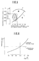
- Fig. 5 graphically shows in terms of engine torque and engine speed the various load 'zones' which are encountered by an automotive vehicle engine.
- the curve F denotes full throttle torque characteristics
- trace L denotes the resistance encountered when a vehicle is running on a level surface
- zones I, II and III denote respectively 'urban cruising', 'high speed cruising' and 'high load opbration , (such as hillclimbing, towing etc.).
- a suitable coblant temperature for zone I is approximately 110°C while 90 - 80°C for zones II and III.
- the high temperature during 'urban cruising' promotes improved charging efficiency while simultaneously rembving sufficient heat from the engine and associated structure to prevent engine knocking and/or engine damage in the other zones.
- the present invention is arranged to positively pump coolant into the system so as to vary the amount of coolant actually in the cooling circuit in a manner which modifies the pressure prevailing therein.
- the combination of the two controls enables the temperature at which the coolant boils to be quickly brought to and held close to that deemed most appropriate for the instant set of operation conditions.
- the present invention also provides for coolant to be positively pumped out of the cooling circiut in a manner which lowers the pressure in the system and supplements the control provide by the fan in a manner which permits the temperature at which the coolant boils to be quickly brought to and held at a level most appropriate for the new set of operating conditions.
- the present invention controls this by again positively pumping coolant into the cooling circuit while it remains in an essentially hermetically sealed state and raises the pressure in the system to a suitable level.
- FIG. 8 of the drawings shows an embodiment of the present invention.
- an internal combution engine 200 includes a cylinder block 204 on which a cylinder head 206 is detachably secured.
- the cylinder head and block are formed with suitably cavities which define a coolant jacket 208 about structure of the engine subject to high heat flux (e.g. combustion chambers exhaust valves conduits etc.,).
- a selectively energizable electrically driven fan 218 Located adjacent the raditor 2 1 6 is a selectively energizable electrically driven fan 218 which is arranged to induce a cooling draft of air to pass over the heat exchanging surface of the radiator 216 upon being put into operation.
- a small collection reservoir 220 or lower tank as it will be referred to hereinlater is provided at the bottom of the radiator 216 and arranged to collect the condensate produced therein.
- a coolant return conduit 222 Leading from the lower tank 220 to a coolant inlet port 221 formed in the cylinder head 206 is a coolant return conduit 222.
- a small capacity electrically driven pump 224 is disposed in this conduit at a location relatively close to the radiator 216.
- this pump 224 is arranged to reversible - that is energizable so as to induct coolant from the lower tank 220 and pump same toward the coolant jacket 208 (viz., pump coolant in a first flow direction) and energizable so as to pump coolant in the reverse direction (second flow direction) - i.e. induct coolant through the return conduit 222 and pump it into the lower tank 220.
- the coolant jacket 208 viz., pump coolant in a first flow direction
- second flow direction i.e. induct coolant
- a coolant reservoir 226 is arranged to communicate with the the lower tank 220 via a supply conduit 228 in which an electromagnetic flow control valve 230 is disposed. This valve is arranged to closed when energized.
- the reservoir 226 is closed by a cap 232 in which a air bleed 234 is formed. This permits the interior of the reservoir 226 to be maintained constantly at amospheric pressure.
- a three-way valve 236 is disposed in the coolant return condiut 222 and arranged to communicate with the reservoir 226 via a level control conduit 238. This valve is arranged to have a first state wherein fluid communication is established between the pump 224 and the reservoir 226 (viz., flow path A) and a second state wherein communication between the pump 224 and the coolant jacket 208 is established (viz., flow path B).
- the vapor manifold 212 is formed with a riser portion 240.
- This riser portion 240 as shown, is provided with a cap 242 which hermetically closes same and further formed with a purge port 244.
- This latter mentioned port 244 communicates with the reservoir 226 via an overflow conduit 246.
- a normally closed ON/OFF type electromagnetic valve 248 is disposed in conduit 246 and arranged to be open only when energized.
- a pressure differential responsive diaphragm operated switch arrangement 250 which assumes an open state upon the pressure prevailing within the cooling circuit (viz., the coolant jacket 208, vapor manifold 214, vapor conduit 214, radiator 216 and return conduit) dropping below atmospheric pressure by a predetermined amount.
- the switch 250 is arranged to open upon the pressure in the cooling circuit falling to a level in the order of -30 to -50mmHg.
- a level sensor 252 is disposed as shown. It will be noted that this sensor 252 is located at a level (H1) which is higher than that of the combustion chambers, exhaust ports and valves (structure subject to high heat flux) so as to maintain same securely immersed in liquid coolant and therefore attenuate engine knocking and the like due to the formation of localized zones of abnormally high temperature or 'hot spots'.
- a temperature sensor 254 Located below the level sensor 252 so as to be immersed in the liquid coolant is a temperature sensor 254.
- the output of the level sensor 252 and the temperature sensor 254 are fed to a control circuit 256 or modulator which is suitably connected with a source of EMF (not shown).
- the control circuit 256 further receives an input from the engine distributor 258 (or like device) which outputs a signal indicative of engine speed and an input from a load sensing device 260 such as a throttle valve position sensor. It will be noted that as an alternative to throttle position, the output of an air flow meter, an induction vacuum sensor or the pulse width of fuel injection control signal may be used to indicate load.
- a second level sensor 262 is disposed in the lower tank 220 at a level H2. The purpose for the provision of this sensor will become clear hereinafter when a discussion the operation of the embodiment is made with reference to the flow charts of Figs. 9 to 18
- the cooling circuit Prior to use the cooling circuit is filled to the brim with coolant (for example water or a mixture of water and antifreeze or the like) and the cap 242 securely set in place to seal the system. A suitable quantity of additional coolant is also placed in the reservoir 226. At this time the electromagnetic valve 230 should be temporarily energized so as to assume a closed condition and three-way valve 236 conditioned to establish flow path B or similar precautions be taken to facilitate the complete filling of the system and the exclusion of any air.
- coolant for example water or a mixture of water and antifreeze or the like
- valve 230 is left de-energized (open) whereby the pressure of the coolant vapor begins displacing liquid coolant out of the cooling circuit (viz., the coolant jacket 208, vapor manifold 212, vapor conduit 214, radiator 216, lower tank 220 and return conduit 222).
- the load and other operational parameters of the engine are sampled and a decision made as to the temperature at which the coolant should be controlled to boil. If the desired temperature is reached before the amount of the coolant in the cooling circuit is reduced to its minimum permissible level (viz., when the coolant in the coolant jacket and the radiator are at levels H1 and H2 respectively) it is possible to energize valve 230 so that is assumes a closed state and places the cooling circuit in a hermetically closed condition.
- three-way valve 236 may be set to establish flow path A and the pump 2 2 4 energized briefly to pump a quantity of coolant out of the cooling circuit to increase the surface 'dry' (internal) surface area of the radiator 2 1 6 available for the coolant vapor to release its latent heat of evaporation and to simultaneously lower the pressure prevailing within the cooling circuit.
- three-way valve 236 is conditioned to produce flow path A and the pump 224 operated to induct coolant from the reservoir 226 and force same into the radiator 216 via the lower tank 220 until it reaches level H3 (by way of example).
- valve 230 When the engine 200 is stopped it is advantageous to maintain valve 230 energized (viz., closed) until the pressure differential responsive switch arrangement 250 opens. This obviates the problem wherein large amounts of coolant are violently discharged from the cooling circuit due to the presence of superatmospheric pressures therein.
- control circuit 256 includes a microprocessor of the nature shown in Fig. 7.
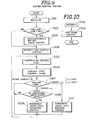
- F ig. 9 shows in flow chart form, the steps which characterize the control the system as a whole.
- the system is initialized (a detailed description of this will be given hereinlater with reference to Fig. 11).
- the output of temperature sensor 254 is sampled and at step 1002 the determination made as to whether to proceed with the non-condensible matter purge routine or not is executed.
- the purge routine step 1003 by-passed and a warm up/displacement mode directly entered at step 1004.
- a first temperature control mode is entered. Viz., a mode wherein the tempeature of the coolant is controlled by varying the rate of heat exchange between the radiator 2 1 6 and the ambient atmosphere via selective energization of the cooling fan 218.
- the operation of the pump 224 is controlled in response to the output of level sensor 252 so as to maintain the cylinder head and other highly heated structure of the engine securely immersed in liquid coolant.
- the coolant temperature is ranged in step 1007 and control of the amount of the coolant actually contained in the cooling circuit of the system controlled (steps 1008 to 1010) in a manner to vary the pressure and hence the temperature at which the coolant will boil.
- Fig. 10 shows an interrupt routine which is executed in the event that the engine is stopped and the necessity for control which obivates loss of coolant from the system via spillage due to the presence of super atmospheric pressures which tend to prevail in the system due to heat which is accumulated in the engine structure per se, induced. This routine will also be discussed in detail hereinafter.
- Fig. 11 shows in detail the steps which are conducted in the initialization step 1001 of Fig. 9.
- the initial check routine starts, at step 3002 the ram or rams of the mocroprocessor are cleared, as step 3003 the peripheral interface adapter is intially set, and in step 3004 the microprocessor is conditioned to allow interrupts.
- Fig. 1 2 shows in detail the steps which characterize the control of the non-condensible matter purge mode.
- the three electromagnetic valves 248, 236 and 230 are conditioned as shown.
- these valves shall be referred to simply as valves I, II and III respectively.
- Viz. valve I (248) is energized so as to assume an open state and thus permit fluid communication between the riser 240 and the reservoir 226 via overflow conduit 246, valve II (236) set so as to assume a condition wherein flow path A is established (viz., fluid communication between the reservoir 226 and the lower tank 220), and valve III (230) is closed.
- pump 224 is energized so as to pump coolant in the second flow direction (viz., toward the lower tank). This causes the freshly introduced coolant (from reservoir 226) to flow up through the radiator 216 toward the riser 240 and thus flush out any stubborn bubbles of air that may have found their way into the system and collected in the radiator tubing.
- step 4004 the operation of the pump 224 is stopped and timer 1 (first timer) cleared ready for the next purge operation.
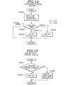
- Fig. 13 shows the control steps which characterize the control of the 'warm-up/displacement control mode of operation.
- valves I, II and III i.e. valves 248, 236 and 230
- valves 248, 236 and 230 are conditioned in a manner which closes the overflow conduit 246 establishes flow path B and which de-energizes valve III (230) to open conduit 228.
- the data input from the sensors 258 and 260 are read and a determination made as to the most appropriate temperature for the coolant to be induced to boil, calculated or otherwise suitably looked up. It will be of course understood that it is within the perview of the instant invention to obtain this data via performing a table look using a table of the nature shown in Fig. 5 of the drawings.
- the coolant circuit still contains an amount of coolant in excess of the above mentioned minimum amount and the program recycles to step 5002 to allow for further displacement.
- the valves are conditioned as shown. Viz., valve I is closed, valve II flow path B is established and valve III is energized to assume a closed state.
- the temperature control (fan) program is run.
- the data inputs from sensors 258 and 260 are read and and the TARGET temperature determined.
- Fig. 15 shows the coolant level control routine which is run after each temperature control rountine execution.
- the level of the coolant in the coolant jacket 208 is determined by sampling the output of level sensor 252. If the level of coolant in the coolant jacket 208 (C/J) is below H2 then at step 7003 pump 224 is energized to pump coolant in the first flow direction from the lower tank 220 toward the coolant jacket 208. The pump 224 is left running until the next run of the coolant level control routine which of course occurs within a very short period of time. When the coolant level has been returned to level H2 the operation of the pump is stopped in step 7002.
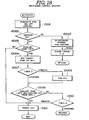
- Fig. 1 6 shows in flow chart form the steps which characterize the control via which the level of coolant in the cooling circuit is reduced for the purposes of coolant temperature control.
- the first step (8001) of this control routine involves the conditioning of the valves so that valve I is closed, valve II establishes flow path A and valve III is energized to assume a closed state.
- pump 224 is energized so as pump coolant in the first flow direction (viz., from the lower tank toward valve II (236). Under these conditions coolant is withdrawn from the lower tank 220 and forced out to the reservoir 226 via conduit 238.
- step 8003 the coolant level in the coolant jacket 208 is checked to determine if the level of coolant therein has dropped to H1 or not. In the event that the level has not dropped to H1 then the program flows to step 8004 wherein the setting of valve II (236) is left as is and the flow path A maintained. On the other hand, if the level in the coolant jacket has in fact dropped to level H1 then as step 8005 the position of valve II is reversed to establish flow path B and thus terminate the discharge of coolant out of the system. Subsequently at step 8006 the coolant level in the lower tank 220 is determined by sampling the output of level sensor 262.
- step 8007 the program proceeds to step 8007 wherein the outputs of sensors 258 and 260 are sampled and the TARGET temperature determined.
- the program by-passes steps 8007 and 8008 as shown.
- step 8007 the instant coolant temperature is compared with the TARGET value derived in step 8007.
- the program returns to step 8003 in an effort to induce a further reduction in coolant and thus internal pressure while in the event that the coolant temperature is lower than TARGET + a5 then the program flows to step 8009 wherein flow path B is established via suitable conditioning of valve II.
- this control strives to lower the temperature of the coolant to a value which is within 1.0°C of the desired TARGET value and is executed in response to the temperature ranging and level sensing steps 1007 and 1008 of the system control routine shown in Fig. 9.
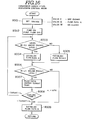
- Fig. 17 shows in detail the steps which characterize the operation wherein the amount of coolant within the cooling circuit is increased in an effort to raise the pressure within the cooling circuit and thus raise the boiling point of the coolant. It will be noted that this control is executed in response to the temperature ranging executed in step 1007 of Fig. 9.
- step 9001 the pressure prevailing in the cooling circuit is sampled and the determination as to whether the pressure is negative of not. This of course can be determined by sampling the output of the pressure differential responsive switch 250.
- step 9002 valve II is condition to provide flow path B while valve III is de-energized to assume an open state. This permits coolant to be inducted into the coolant circiut under the influence of the pressure differential which exists between the ambient atmosphere and the interior of the cooling system.
- step 9003 the coolant level control routine shown in Fi g. 15 is executed.
- valve III is energized so as to asume a closed state.
- the coolant level in the coolant jacket 208 is determined and if lower than H 1 then at step 9006 valve II is conditioned to provide flow path B and at step 9007 pump 224 is energized in a manner to pump liquid coolant in the first flow direction.
- flow path A is established and pump 224 operated to pump coolant in the second flow direction. This of course positively inducts coolant from the reservoir 226 and forces same into the cooling circuit (radiator 216) to increase the pressure prevailing therein.
- the TARGET temperature is derived and at step 9011 the instant coolant. temperature compared with the derived value. In the event that the coolant temperature is below TARGET - a6 then the program recycles to step 9001 in order to permit further coolant to be introduced into the cooling circuit.
- step 9012 flow path I is and valve III closed thus terminating the iiflux of coolant.
- step 10001 the normal ON/OFF operation 3 f fan 218 is terminated and the fan conditioned to continuously operate while at step 1 0002 the condition of the ignition key is sampled. If the key is still in the 'ON' position it is assumed that the engine will be immediately restarted and the program flows to steps 10003 and 10004 wherein normal ON/OFF control of the fan is reinstated and timers 2 and 3 cleared.
- step 10005 it is determined if the temperature of the engine coolant is above a predetemined level which in this embodiment is selected to be 80°C. If the temperature of the coolant is still below the just mentioned limit it is assumed that the cooling circuit can be rendered open circuit without fear of super atmospheric pressures causing a violent displacement of coolant out of the circuit to the reservoir in a manner which invites spillage and permanent loss of coolant. On the other hand, if the coolant is still above 80°C then the program flows to step 1 0006 wherein the TARGET temperature is set to the just mentioned value. At step 10007 a second timer (timer 2) is set counting.
- timer 2 timer 2 is set counting.
- the period for which the second counter is arranged to count over is selected to be 1 minute. If desired this value can be increased or decreased in view of the engine which is cooled by the system according to the present invention.
- step 10009 enquires relating to the temperature and pressure status of the interior of the cooling circuit are carried out. Viz., it is determined if the coolant temperature is below 97°C and the pressure prevailing within the system negative.
- step 10011 power to the entire system is cut off. However, if one or the other of the two requirements is not met then the program flows to step 10010 wherein timer 3 is set counting and the program goes to RETURN.
- the period for which the third counter is arranged to count is in this embodiment is 1 minute.
- the third counter completes its count the program goes to step 10011 and terminates.
- the shut-down control routine may be run a number of times before the power to the entire system is cut-off. This of course ensures that the above mentioned spillage etc., will not occur.
Landscapes
- Engineering & Computer Science (AREA)
- Chemical & Material Sciences (AREA)
- Combustion & Propulsion (AREA)
- Mechanical Engineering (AREA)
- General Engineering & Computer Science (AREA)
- Combined Controls Of Internal Combustion Engines (AREA)
- Engine Equipment That Uses Special Cycles (AREA)
Applications Claiming Priority (2)
| Application Number | Priority Date | Filing Date | Title |
|---|---|---|---|
| JP59140378A JPS6119919A (ja) | 1984-07-06 | 1984-07-06 | 内燃機関の沸騰冷却装置 |
| JP140378/84 | 1984-07-06 |
Publications (3)
| Publication Number | Publication Date |
|---|---|
| EP0167169A2 true EP0167169A2 (de) | 1986-01-08 |
| EP0167169A3 EP0167169A3 (en) | 1986-12-03 |
| EP0167169B1 EP0167169B1 (de) | 1989-05-03 |
Family
ID=15267426
Family Applications (1)
| Application Number | Title | Priority Date | Filing Date |
|---|---|---|---|
| EP85108305A Expired EP0167169B1 (de) | 1984-07-06 | 1985-07-04 | Kühlvorrichtung für eine Kraftfahrzeugmaschine |
Country Status (4)
| Country | Link |
|---|---|
| US (1) | US4616602A (de) |
| EP (1) | EP0167169B1 (de) |
| JP (1) | JPS6119919A (de) |
| DE (1) | DE3569958D1 (de) |
Cited By (1)
| Publication number | Priority date | Publication date | Assignee | Title |
|---|---|---|---|---|
| EP0189881A2 (de) * | 1985-01-28 | 1986-08-06 | Nissan Motor Co., Ltd. | Kühlvorrichtung einer Kraftfahrzeugmaschine |
Families Citing this family (10)
| Publication number | Priority date | Publication date | Assignee | Title |
|---|---|---|---|---|
| JPS62223439A (ja) * | 1986-03-22 | 1987-10-01 | Nissan Motor Co Ltd | 沸騰冷却式内燃機関のノツキング制御装置 |
| JPH073172B2 (ja) * | 1986-04-11 | 1995-01-18 | 日産自動車株式会社 | 内燃機関の沸騰冷却装置 |
| US5582138A (en) * | 1995-03-17 | 1996-12-10 | Standard-Thomson Corporation | Electronically controlled engine cooling apparatus |
| DE19637248C2 (de) * | 1996-09-13 | 1998-09-17 | Gwk Ges Waerme Kaeltetechnik M | Verfahren und Vorrichtung zur Abfuhr thermischer Energie aus einem Kühlkreislauf mit einem Wärme erzeugenden Verbraucher |
| KR100348588B1 (ko) * | 2000-07-07 | 2002-08-14 | 국방과학연구소 | 차량용 냉각장치 |
| US7367291B2 (en) * | 2004-07-23 | 2008-05-06 | General Electric Co. | Locomotive apparatus |
| JP2008021613A (ja) * | 2006-07-14 | 2008-01-31 | Tokai Rika Co Ltd | 照明装置 |
| US20100147004A1 (en) * | 2008-12-15 | 2010-06-17 | Tai-Her Yang | Heat pump or heat exchange device with periodic positive and reverse pumping |
| JP2013256936A (ja) * | 2012-05-16 | 2013-12-26 | Denso Corp | 排気還流装置 |
| CN104373193A (zh) * | 2014-11-19 | 2015-02-25 | 力帆实业(集团)股份有限公司 | 一种带膨胀水壶液面报警提示的汽车冷却系统 |
Citations (8)
| Publication number | Priority date | Publication date | Assignee | Title |
|---|---|---|---|---|
| US1338722A (en) * | 1916-06-02 | 1920-05-04 | Essex Motors | Cooling apparatus for internal-combustion engines |
| US1651157A (en) * | 1924-10-27 | 1927-11-29 | Samuel W Rushmore | Cooling system |
| US1792520A (en) * | 1926-06-03 | 1931-02-17 | Packard Motor Car Co | Internal-combustion engine |
| US2093599A (en) * | 1930-10-15 | 1937-09-21 | Clough Clarence Roy | Water storage and circulating system for motor vehicles |
| DE736381C (de) * | 1940-03-12 | 1943-06-15 | Messerschmitt Boelkow Blohm | Arbeitsverfahren fuer luftgekuehlte Dampfkondensatoren |
| EP0121182A1 (de) * | 1983-03-31 | 1984-10-10 | Nissan Motor Co., Ltd. | Vorrichtung zum Regeln des Kühlmittelniveaus für Brennkraftmaschine |
| EP0140162A2 (de) * | 1983-10-28 | 1985-05-08 | Nissan Motor Co., Ltd. | Kühlanlage für Kraftwagenbrennkraftmaschine |
| EP0146057A2 (de) * | 1983-12-02 | 1985-06-26 | Nissan Motor Co., Ltd. | Kühlungsvorrichtung für Kraftwagenmaschinen |
Family Cites Families (6)
| Publication number | Priority date | Publication date | Assignee | Title |
|---|---|---|---|---|
| US1787562A (en) * | 1929-01-10 | 1931-01-06 | Lester P Barlow | Engine-cooling system |
| US4367699A (en) * | 1981-01-27 | 1983-01-11 | Evc Associates Limited Partnership | Boiling liquid engine cooling system |
| US4425766A (en) * | 1982-05-17 | 1984-01-17 | General Motors Corporation | Motor vehicle cooling fan power management system |
| DE3464401D1 (en) * | 1983-03-31 | 1987-07-30 | Nissan Motor | Load responsive temperature control arrangement for internal combustion engine |
| JPS6017255A (ja) * | 1983-07-11 | 1985-01-29 | Nissan Motor Co Ltd | 沸騰冷却方式エンジンのシリンダヘツド |
| US4549505A (en) * | 1983-10-25 | 1985-10-29 | Nissan Motor Co., Ltd. | Cooling system for automotive engine or the like |
-
1984
- 1984-07-06 JP JP59140378A patent/JPS6119919A/ja active Granted
-
1985
- 1985-07-03 US US06/751,536 patent/US4616602A/en not_active Expired - Lifetime
- 1985-07-04 EP EP85108305A patent/EP0167169B1/de not_active Expired
- 1985-07-04 DE DE8585108305T patent/DE3569958D1/de not_active Expired
Patent Citations (8)
| Publication number | Priority date | Publication date | Assignee | Title |
|---|---|---|---|---|
| US1338722A (en) * | 1916-06-02 | 1920-05-04 | Essex Motors | Cooling apparatus for internal-combustion engines |
| US1651157A (en) * | 1924-10-27 | 1927-11-29 | Samuel W Rushmore | Cooling system |
| US1792520A (en) * | 1926-06-03 | 1931-02-17 | Packard Motor Car Co | Internal-combustion engine |
| US2093599A (en) * | 1930-10-15 | 1937-09-21 | Clough Clarence Roy | Water storage and circulating system for motor vehicles |
| DE736381C (de) * | 1940-03-12 | 1943-06-15 | Messerschmitt Boelkow Blohm | Arbeitsverfahren fuer luftgekuehlte Dampfkondensatoren |
| EP0121182A1 (de) * | 1983-03-31 | 1984-10-10 | Nissan Motor Co., Ltd. | Vorrichtung zum Regeln des Kühlmittelniveaus für Brennkraftmaschine |
| EP0140162A2 (de) * | 1983-10-28 | 1985-05-08 | Nissan Motor Co., Ltd. | Kühlanlage für Kraftwagenbrennkraftmaschine |
| EP0146057A2 (de) * | 1983-12-02 | 1985-06-26 | Nissan Motor Co., Ltd. | Kühlungsvorrichtung für Kraftwagenmaschinen |
Cited By (3)
| Publication number | Priority date | Publication date | Assignee | Title |
|---|---|---|---|---|
| EP0189881A2 (de) * | 1985-01-28 | 1986-08-06 | Nissan Motor Co., Ltd. | Kühlvorrichtung einer Kraftfahrzeugmaschine |
| EP0189881A3 (en) * | 1985-01-28 | 1986-11-26 | Nissan Motor Co., Ltd. | Cooling system for automotive engine or the like |
| US4664073A (en) * | 1985-01-28 | 1987-05-12 | Nissan Motor Co., Ltd. | Cooling system for automotive engine or the like |
Also Published As
| Publication number | Publication date |
|---|---|
| DE3569958D1 (en) | 1989-06-08 |
| JPH0475369B2 (de) | 1992-11-30 |
| JPS6119919A (ja) | 1986-01-28 |
| EP0167169A3 (en) | 1986-12-03 |
| EP0167169B1 (de) | 1989-05-03 |
| US4616602A (en) | 1986-10-14 |
Similar Documents
| Publication | Publication Date | Title |
|---|---|---|
| EP0143326B1 (de) | Kühlvorrichtung für eine Kraftfahrzeugmaschine | |
| US4788943A (en) | Cooling system for automotive engine or the like | |
| US4648357A (en) | Cooling system for automotive engine or the like | |
| EP0126422B1 (de) | Kühlanlage für Fahrzeugbrennkraftmaschinen | |
| EP0167169B1 (de) | Kühlvorrichtung für eine Kraftfahrzeugmaschine | |
| US4658766A (en) | Cooling system for automotive engine or the like | |
| EP0207354B1 (de) | Verfahren und Vorrichtung zum Kühlen von Fahrzeugbrennkraftmaschinen | |
| US4782795A (en) | Anti-knock system for automotive internal combustion engine | |
| EP0161687B1 (de) | Kühlungsanlage für eine Kraftwagenmaschine | |
| US4694784A (en) | Cooling system for automotive engine or the like | |
| US4669426A (en) | Cooling system for automotive engine or the like | |
| US4574747A (en) | Cooling system for automotive engine | |
| US4628872A (en) | Cooling system for automotive engine or the like including coolant return pump back-up arrangement | |
| US4605164A (en) | Cabin heating arrangement for vehicle having evaporative cooled engine | |
| US4630573A (en) | Cooling system for automotive engine or the like | |
| US4677942A (en) | Cooling system for automotive engine or the like | |
| US4622925A (en) | Cooling system for automotive engine or the like | |
| US4662318A (en) | Cooling system for automotive internal combustion engine or the like | |
| US4627397A (en) | Cooling system for automotive engine or the like | |
| US4646688A (en) | Cooling system for automotive engine or the like | |
| US4630574A (en) | Cooling system for automotive engine or the like | |
| EP0153694B1 (de) | Kühlverfahren und Kühlsystem für Brennkraftmaschinen | |
| US4662316A (en) | Cooling system for automotive engine or the like | |
| US4721071A (en) | Cooling system for automotive engine or the like | |
| US4624221A (en) | Cooling system for automotive engine or the like |
Legal Events
| Date | Code | Title | Description |
|---|---|---|---|
| PUAI | Public reference made under article 153(3) epc to a published international application that has entered the european phase |
Free format text: ORIGINAL CODE: 0009012 |
|
| 17P | Request for examination filed |
Effective date: 19850704 |
|
| AK | Designated contracting states |
Designated state(s): DE FR GB |
|
| PUAL | Search report despatched |
Free format text: ORIGINAL CODE: 0009013 |
|
| RHK1 | Main classification (correction) |
Ipc: F01P 3/22 |
|
| AK | Designated contracting states |
Kind code of ref document: A3 Designated state(s): DE FR GB |
|
| 17Q | First examination report despatched |
Effective date: 19870928 |
|
| GRAA | (expected) grant |
Free format text: ORIGINAL CODE: 0009210 |
|
| AK | Designated contracting states |
Kind code of ref document: B1 Designated state(s): DE FR GB |
|
| REF | Corresponds to: |
Ref document number: 3569958 Country of ref document: DE Date of ref document: 19890608 |
|
| ET | Fr: translation filed | ||
| PLBE | No opposition filed within time limit |
Free format text: ORIGINAL CODE: 0009261 |
|
| STAA | Information on the status of an ep patent application or granted ep patent |
Free format text: STATUS: NO OPPOSITION FILED WITHIN TIME LIMIT |
|
| 26N | No opposition filed | ||
| PGFP | Annual fee paid to national office [announced via postgrant information from national office to epo] |
Ref country code: FR Payment date: 19910708 Year of fee payment: 7 |
|
| PG25 | Lapsed in a contracting state [announced via postgrant information from national office to epo] |
Ref country code: FR Effective date: 19930331 |
|
| REG | Reference to a national code |
Ref country code: FR Ref legal event code: ST |
|
| REG | Reference to a national code |
Ref country code: GB Ref legal event code: IF02 |
|
| PGFP | Annual fee paid to national office [announced via postgrant information from national office to epo] |
Ref country code: GB Payment date: 20030702 Year of fee payment: 19 |
|
| PGFP | Annual fee paid to national office [announced via postgrant information from national office to epo] |
Ref country code: DE Payment date: 20030717 Year of fee payment: 19 |
|
| PG25 | Lapsed in a contracting state [announced via postgrant information from national office to epo] |
Ref country code: GB Free format text: LAPSE BECAUSE OF NON-PAYMENT OF DUE FEES Effective date: 20040704 |
|
| PG25 | Lapsed in a contracting state [announced via postgrant information from national office to epo] |
Ref country code: DE Free format text: LAPSE BECAUSE OF NON-PAYMENT OF DUE FEES Effective date: 20050201 |
|
| GBPC | Gb: european patent ceased through non-payment of renewal fee |
Effective date: 20040704 |