EP0166358B1 - Dispositif de commande de la liaison d'un circuit électrique à un réseau - Google Patents
Dispositif de commande de la liaison d'un circuit électrique à un réseau Download PDFInfo
- Publication number
- EP0166358B1 EP0166358B1 EP85107505A EP85107505A EP0166358B1 EP 0166358 B1 EP0166358 B1 EP 0166358B1 EP 85107505 A EP85107505 A EP 85107505A EP 85107505 A EP85107505 A EP 85107505A EP 0166358 B1 EP0166358 B1 EP 0166358B1
- Authority
- EP
- European Patent Office
- Prior art keywords
- flip
- capacitor
- flop
- resistor
- switch
- Prior art date
- Legal status (The legal status is an assumption and is not a legal conclusion. Google has not performed a legal analysis and makes no representation as to the accuracy of the status listed.)
- Expired
Links
- 239000003990 capacitor Substances 0.000 claims description 44
- 238000011144 upstream manufacturing Methods 0.000 claims description 5
- 238000004804 winding Methods 0.000 description 3
- 230000008033 biological extinction Effects 0.000 description 2
- 230000005284 excitation Effects 0.000 description 2
- 230000005281 excited state Effects 0.000 description 2
- 238000009499 grossing Methods 0.000 description 2
- 238000010521 absorption reaction Methods 0.000 description 1
- 238000001816 cooling Methods 0.000 description 1
- 239000007789 gas Substances 0.000 description 1
- 244000045947 parasite Species 0.000 description 1
- 230000002035 prolonged effect Effects 0.000 description 1
Images
Classifications
-
- H—ELECTRICITY
- H01—ELECTRIC ELEMENTS
- H01H—ELECTRIC SWITCHES; RELAYS; SELECTORS; EMERGENCY PROTECTIVE DEVICES
- H01H47/00—Circuit arrangements not adapted to a particular application of the relay and designed to obtain desired operating characteristics or to provide energising current
- H01H47/02—Circuit arrangements not adapted to a particular application of the relay and designed to obtain desired operating characteristics or to provide energising current for modifying the operation of the relay
- H01H47/18—Circuit arrangements not adapted to a particular application of the relay and designed to obtain desired operating characteristics or to provide energising current for modifying the operation of the relay for introducing delay in the operation of the relay
-
- H—ELECTRICITY
- H05—ELECTRIC TECHNIQUES NOT OTHERWISE PROVIDED FOR
- H05B—ELECTRIC HEATING; ELECTRIC LIGHT SOURCES NOT OTHERWISE PROVIDED FOR; CIRCUIT ARRANGEMENTS FOR ELECTRIC LIGHT SOURCES, IN GENERAL
- H05B47/00—Circuit arrangements for operating light sources in general, i.e. where the type of light source is not relevant
- H05B47/10—Controlling the light source
Definitions
- the influence of the device on the supply circuit varies according to the operating conditions of the device itself.
- the inductance is high only when the lamp is on. Consequently, as long as the lamp is not lit, the reactive power due to the capacitor is not compensated and this results in disturbances on the network as long as the discharge lamp is connected to the network without being switched on.
- a discharge lamp can only light up when the gases it contains have cooled down.
- the lamps go out and can only re-light after a certain time during which the capacitors create a disturbance on the network.
- a short cut leading to the extinction of the lamps subsequently causes a very significant disturbance which must be compensated by a increase in the power supplied to the network, failing which the reactive power of the capacitors is not compensated and the discharge lamps cannot be re-ignited.
- a device for controlling an electrical circuit characterized in that it comprises a first controlled switch open at rest, mounted on the electrical circuit, a second controlled switch, closed at rest, mounted in parallel with the first controlled switch, supply means of the control device connected to the electrical circuit upstream of the first and second controlled switches, first time-delay control means connected to the first controlled switch, second means of timing control connected to the second controlled switch and memory means connected to the second controlled switch, the timing of the first control means being at most equal to the timing of the second control means.
- the timing means comprise a resistor, one terminal of which is connected to the supply means and the other terminal of which is connected on the one hand to the input of the first flip-flop corresponding and on the other hand to a first terminal of a capacitor
- the holding means comprise a second flip-flop whose input is connected to the output of the first flip-flop and whose output is connected to a second terminal of the capacitor opposite to the first one.
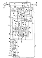
- the control device of an electrical circuit 1 comprises a first switch 2, open at rest,. controlled by a coil 3 and mounted on the electrical circuit 1, a second switch 4 closed at rest, mounted in parallel with the first switch 2 and controlled by a coil 5.
- the timing means 23 also include a capacitor 27 one of the terminals of which is also connected to line 26, while the other terminal is connected to ground through the inter medium of means for holding the control means in an activated position.
- These holding means are formed by a second flip-flop 28, one of the inputs of which is connected directly to ground and the other input of which is connected by a line 29 to the output of the first flip-flop 18, the output of the flip-flop 28 being connected to the terminal of the capacitor 27 which is opposite to the terminal of this same capacitor connected to the input of the rocker 18.
- Second timing control means comprise, in the same way as the first timing means 17, a flip-flop 31, connected via a resistor 32 to an NPN transistor 33.
- Timing means 34 comprise a resistor 35, one of which terminals is connected to the supply means 6 by a line 36 and the other terminal of which is connected to the input of the rocker 31.
- the timing means 34 also comprise a capacitor 37, a first terminal of which is connected to the input of the flip-flop 31 and the opposite terminal of which is connected to the output of a flip-flop 38 forming means for holding the control means 30 in an activated position.
- the flip-flop 38 has one of its input terminals connected to ground and the other input terminal connected to the output of the first flip-flop 31 by a line 39.
- the emitter of transistor 33 is connected to ground by a line 40 and the collector is connected to memory means 41, by means of a decoupling diode 42.
- the memory means 41 include a capacitor 43, one of which terminals is connected to the supply means 6 by a line 44 and is associated with a resistor 46, mounted in parallel with the terminals of the capacitor, by means of a resistor 45.
- the memory means 41 further comprise a second resistor 47, mounted in parallel with the first resistor 46 and in series with a switch 48, open at rest and controlled by a coil 49, one terminal of which is connected to the supply means 6 by a line 50 and the other bounded of which is grounded.
- the signal of the memory means is amplified by a PNP transistor 51, the base of which is connected to one of the common terminals of the resistors 46 and 47, the emitter of which is connected to the supply means 6 by a line 52 and of which the collector is connected to the base of an NPN transistor 53, via a resistor 54.
- the collector of transistor 53 is connected to the terminal of the coil 5 opposite to that which is connected to the supply means 6
- the emitter of transistor 53 is connected to ground by a line 55 and its base is also connected to ground via a resistor 56.
- Diodes 57, 58 and 59 are respectively mounted in parallel with the coils 3, 5 and 49 in order to protect the transistors against self-induction of these coils, during the interruption of the current therein.
- the operation of the device is as follows when establishing the connection with the AC voltage source 60, the switch 4 is closed and the current can flow normally towards the use, for example, a discharge lamp 61 which is cold and then lights up instantly.
- the flip-flop 18 is at rest and the transistor 20 is therefore blocked.
- the coil 3 is therefore not energized and the switch 2 is open.
- the coils 3 and 5 cease to be excited and the switches 2 and 4 return to their rest position.
- the capacitors 27 and 37 discharge almost instantaneously and the rockers 18 and 31 return to their initial state.
- the capacitor 43 which has been charged, via the transistor 33, during the preceding supply period, keeps the transistor 51 conductive and gradually discharges through resistors 45, 46.
- the flip-flop 18 remains in the idle state as long as the capacitor 27 is not charged again and the switch 2 therefore remains open during this time.
- the transistors 51 and 53 are kept conductive by the discharge of the capacitor 43 and the coil 5 is therefore excited, which opens the switch 4. Consequently, as long as the capacitor 43 is not discharged, the device 61 is disconnected from the network.
- the capacitor 43 is chosen to have a discharge time equal to the cooling time of the lamp, so that when the switch 4 closes the ignition of the lamp 61 can be instantaneous and not cause disturbances on the network.
Landscapes
- Circuit Arrangement For Electric Light Sources In General (AREA)
- Electronic Switches (AREA)
Applications Claiming Priority (2)
| Application Number | Priority Date | Filing Date | Title |
|---|---|---|---|
| FR8409673 | 1984-06-20 | ||
| FR8409673A FR2566576B1 (fr) | 1984-06-20 | 1984-06-20 | Dispositif de commande de la liaison d'un circuit electrique a un reseau |
Publications (2)
| Publication Number | Publication Date |
|---|---|
| EP0166358A1 EP0166358A1 (fr) | 1986-01-02 |
| EP0166358B1 true EP0166358B1 (fr) | 1989-01-04 |
Family
ID=9305234
Family Applications (1)
| Application Number | Title | Priority Date | Filing Date |
|---|---|---|---|
| EP85107505A Expired EP0166358B1 (fr) | 1984-06-20 | 1985-06-18 | Dispositif de commande de la liaison d'un circuit électrique à un réseau |
Country Status (5)
| Country | Link |
|---|---|
| US (1) | US4636652A (da) |
| EP (1) | EP0166358B1 (da) |
| DE (1) | DE3567350D1 (da) |
| DK (1) | DK274885A (da) |
| FR (1) | FR2566576B1 (da) |
Families Citing this family (18)
| Publication number | Priority date | Publication date | Assignee | Title |
|---|---|---|---|---|
| US4833339A (en) * | 1983-10-13 | 1989-05-23 | Lutron Electronics Co., Inc. | Load control system |
| US7330886B2 (en) * | 1999-10-27 | 2008-02-12 | American Power Conversion Corporation | Network appliance management |
| US7392309B2 (en) * | 1999-10-27 | 2008-06-24 | American Power Conversion Corporation | Network appliance management |
| US6714977B1 (en) | 1999-10-27 | 2004-03-30 | Netbotz, Inc. | Method and system for monitoring computer networks and equipment |
| US8271626B2 (en) | 2001-01-26 | 2012-09-18 | American Power Conversion Corporation | Methods for displaying physical network topology and environmental status by location, organization, or responsible party |
| ES2340469T3 (es) | 2001-01-26 | 2010-06-04 | American Power Conversion Corporation | Procedimiento y sistema para un conjunto de dispositivos de red que pueden conectarse para mejorar la colaboracion , la escalabilidad y la fiabilidad. |
| AU2003232039A1 (en) * | 2002-05-03 | 2003-11-17 | Netbotz, Inc. | Method and apparatus for collecting and displaying network device information |
| US8566292B2 (en) | 2003-04-14 | 2013-10-22 | Schneider Electric It Corporation | Method and system for journaling and accessing sensor and configuration data |
| EP1616235B1 (en) * | 2003-04-14 | 2009-11-25 | American Power Conversion Corporation | Extensible sensor monitoring, alert processing and notification system and method |
| US7148796B2 (en) * | 2003-04-14 | 2006-12-12 | American Power Conversion Corporation | Environmental monitoring device |
| WO2004092909A2 (en) * | 2003-04-14 | 2004-10-28 | Netbotz, Inc. | Method and system for journaling and accessing sensor and configuration data |
| US7627651B2 (en) * | 2003-10-27 | 2009-12-01 | American Power Conversion Corporation | System and method for network device communication |
| AU2008255030B2 (en) | 2007-05-15 | 2014-02-20 | Schneider Electric It Corporation | Methods and systems for managing facility power and cooling |
| CN102081367A (zh) * | 2011-01-25 | 2011-06-01 | 浙江申乐电气有限公司 | 简易定时器 |
| CN102074417A (zh) * | 2011-01-25 | 2011-05-25 | 浙江申乐电气有限公司 | 一位数字定时器 |
| US8990536B2 (en) | 2011-06-01 | 2015-03-24 | Schneider Electric It Corporation | Systems and methods for journaling and executing device control instructions |
| WO2013095516A1 (en) | 2011-12-22 | 2013-06-27 | Schneider Electric It Corporation | Analysis of effect of transient events on temperature in a data center |
| CN102693871B (zh) * | 2012-06-06 | 2016-01-27 | 张新连 | 节能控制开关 |
Family Cites Families (10)
| Publication number | Priority date | Publication date | Assignee | Title |
|---|---|---|---|---|
| DE1292717B (de) * | 1963-11-11 | 1969-04-17 | Schleicher Gmbh & Co | Elektrisch fernsteuerbarer Zeitschalter mit einem verzoegert arbeitenden und einem unverzoegert arbeitenden Kontakt |
| US3814950A (en) * | 1972-12-08 | 1974-06-04 | W Adams | Timing circuit |
| US3940660A (en) * | 1973-12-14 | 1976-02-24 | Edwards Frederick H | Circuitry for load connection and disconnection |
| DE2607025C2 (de) * | 1976-02-19 | 1983-12-08 | Siemens AG, 1000 Berlin und 8000 München | Elektronische Zeitschaltvorrichtung |
| US4204128A (en) * | 1978-03-13 | 1980-05-20 | Westinghouse Electric Corp. | Adjustable time delay relay |
| NL7909127A (nl) * | 1979-12-19 | 1981-07-16 | Philips Nv | Elektrische inrichting voorzien van een gas- en/of dampontladingslamp. |
| US4396872A (en) * | 1981-03-30 | 1983-08-02 | General Mills, Inc. | Ballast circuit and method for optimizing the operation of high intensity discharge lamps in the growing of plants |
| US4426639A (en) * | 1981-09-01 | 1984-01-17 | Robert S. Kaiser | Timing apparatus |
| US4536693A (en) * | 1982-09-02 | 1985-08-20 | Ltv Aerospace And Defense Company | High-speed capacitor discharge circuit suitable for the protection of detonation devices |
| US4507569A (en) * | 1983-12-30 | 1985-03-26 | Conservolite, Inc. | Electrical control system and driver |
-
1984
- 1984-06-20 FR FR8409673A patent/FR2566576B1/fr not_active Expired
-
1985
- 1985-06-18 DK DK274885A patent/DK274885A/da not_active Application Discontinuation
- 1985-06-18 DE DE8585107505T patent/DE3567350D1/de not_active Expired
- 1985-06-18 EP EP85107505A patent/EP0166358B1/fr not_active Expired
- 1985-06-19 US US06/746,424 patent/US4636652A/en not_active Expired - Fee Related
Also Published As
| Publication number | Publication date |
|---|---|
| US4636652A (en) | 1987-01-13 |
| DK274885A (da) | 1985-12-21 |
| DK274885D0 (da) | 1985-06-18 |
| FR2566576A1 (fr) | 1985-12-27 |
| DE3567350D1 (en) | 1989-02-09 |
| FR2566576B1 (fr) | 1987-01-16 |
| EP0166358A1 (fr) | 1986-01-02 |
Similar Documents
| Publication | Publication Date | Title |
|---|---|---|
| EP0166358B1 (fr) | Dispositif de commande de la liaison d'un circuit électrique à un réseau | |
| FR2794334A1 (fr) | Ballast pour lampe a decharge comportant un convertisseur de tension | |
| FR2668329A1 (fr) | Circuit d'allumage de lampe a decharge pour vehicule. | |
| EP0066481A1 (fr) | Dispositif d'alimentation électronique pour lampes à décharge | |
| FR2915180A1 (fr) | Groupe d'alimentation electrique destine a servir avec un reseau electrique d'avion | |
| FR2535117A1 (fr) | Circuit de protection de cellule a combustible | |
| EP0695112B1 (fr) | Circuit de montage de diodes électroluminescentes | |
| EP0271396A1 (fr) | Procédé et dispositif pour l'allumage de lampes à décharge | |
| EP0284592B1 (fr) | Dispositif permettant le rétablissement du courant de ligne en cas de claquage d'un ou de plusieurs éléments d'un montage en série | |
| EP0836280B1 (fr) | Interrupteur électronique à alimentation deux fils | |
| FR2544055A1 (fr) | Generateur de courant pour l'alimentation et la detection de fonctionnement d'un bruleur a gaz et dispositif de commande et de controle en faisant application | |
| EP0077531A1 (fr) | Dispositif de charge d'un ensemble de batteries, notamment de batteries tampons alimentées par une source d'énergie de puissance limitée | |
| EP0023870B1 (fr) | Perfectionnements aux dispositifs pour commander avec sécurité des vannes de gaz | |
| EP0539301A1 (fr) | Dispositif de couplage d'une source extérieure d'alimentation en énergie électrique à un avion au sol | |
| FR2720558A1 (fr) | Système d'alimentation sécurisé. | |
| EP0164770B1 (fr) | Relais statique pour courant continu basse tension | |
| EP0133089A1 (fr) | Circuit de commande de puissance, à courant continu, avec protection contre les surcharges et les courts-circuits | |
| FR2488753A1 (fr) | Commande de moteur electrique a courant alternatif | |
| FR2477282A1 (fr) | Dispositif de controle de la capacite de batteries d'accumulateurs | |
| FR2616929A1 (fr) | Dispositif de commande de test d'autonomie pour un ensemble de blocs d'eclairage de securite | |
| SU943961A1 (ru) | Устройство дл защиты электропотребител от минимального напр жени с выдержкой времени | |
| FR2737057A1 (fr) | Circuit de communication a signalisation de defaut et module de test associe | |
| EP0978941A1 (fr) | Circuit de production d'arcs électriques | |
| FR2671240A1 (fr) | Dispositif de commande d'un disjoncteur en cas de rupture de la ligne neutre. | |
| BE702291A (da) |
Legal Events
| Date | Code | Title | Description |
|---|---|---|---|
| PUAI | Public reference made under article 153(3) epc to a published international application that has entered the european phase |
Free format text: ORIGINAL CODE: 0009012 |
|
| AK | Designated contracting states |
Designated state(s): BE DE FR GB IT LU NL SE |
|
| 17P | Request for examination filed |
Effective date: 19860702 |
|
| RAP1 | Party data changed (applicant data changed or rights of an application transferred) |
Owner name: ALCATEL |
|
| RAP1 | Party data changed (applicant data changed or rights of an application transferred) |
Owner name: ALCATEL CIT |
|
| 17Q | First examination report despatched |
Effective date: 19880610 |
|
| GRAA | (expected) grant |
Free format text: ORIGINAL CODE: 0009210 |
|
| AK | Designated contracting states |
Kind code of ref document: B1 Designated state(s): BE DE FR GB IT LU NL SE |
|
| PG25 | Lapsed in a contracting state [announced via postgrant information from national office to epo] |
Ref country code: NL Effective date: 19890104 Ref country code: IT Free format text: LAPSE BECAUSE OF FAILURE TO SUBMIT A TRANSLATION OF THE DESCRIPTION OR TO PAY THE FEE WITHIN THE PRESCRIBED TIME-LIMIT;WARNING: LAPSES OF ITALIAN PATENTS WITH EFFECTIVE DATE BEFORE 2007 MAY HAVE OCCURRED AT ANY TIME BEFORE 2007. THE CORRECT EFFECTIVE DATE MAY BE DIFFERENT FROM THE ONE RECORDED. Effective date: 19890104 Ref country code: GB Free format text: LAPSE BECAUSE OF NON-PAYMENT OF DUE FEES Effective date: 19890104 |
|
| REF | Corresponds to: |
Ref document number: 3567350 Country of ref document: DE Date of ref document: 19890209 |
|
| NLV1 | Nl: lapsed or annulled due to failure to fulfill the requirements of art. 29p and 29m of the patents act | ||
| PG25 | Lapsed in a contracting state [announced via postgrant information from national office to epo] |
Ref country code: SE Effective date: 19890619 |
|
| PG25 | Lapsed in a contracting state [announced via postgrant information from national office to epo] |
Ref country code: LU Free format text: LAPSE BECAUSE OF NON-PAYMENT OF DUE FEES Effective date: 19890630 Ref country code: BE Effective date: 19890630 |
|
| GBV | Gb: ep patent (uk) treated as always having been void in accordance with gb section 77(7)/1977 [no translation filed] | ||
| PLBE | No opposition filed within time limit |
Free format text: ORIGINAL CODE: 0009261 |
|
| STAA | Information on the status of an ep patent application or granted ep patent |
Free format text: STATUS: NO OPPOSITION FILED WITHIN TIME LIMIT |
|
| 26N | No opposition filed | ||
| BERE | Be: lapsed |
Owner name: ALCATEL CIT Effective date: 19890630 |
|
| PG25 | Lapsed in a contracting state [announced via postgrant information from national office to epo] |
Ref country code: FR Free format text: LAPSE BECAUSE OF NON-PAYMENT OF DUE FEES Effective date: 19900228 |
|
| PG25 | Lapsed in a contracting state [announced via postgrant information from national office to epo] |
Ref country code: DE Effective date: 19900301 |
|
| REG | Reference to a national code |
Ref country code: FR Ref legal event code: ST |
|
| EUG | Se: european patent has lapsed |
Ref document number: 85107505.1 Effective date: 19900418 |