EP0166352B1 - Arrangement for pointing a directable device towards a light source - Google Patents
Arrangement for pointing a directable device towards a light source Download PDFInfo
- Publication number
- EP0166352B1 EP0166352B1 EP85107475A EP85107475A EP0166352B1 EP 0166352 B1 EP0166352 B1 EP 0166352B1 EP 85107475 A EP85107475 A EP 85107475A EP 85107475 A EP85107475 A EP 85107475A EP 0166352 B1 EP0166352 B1 EP 0166352B1
- Authority
- EP
- European Patent Office
- Prior art keywords
- light source
- azimuthal
- receiver
- radial
- light
- Prior art date
- Legal status (The legal status is an assumption and is not a legal conclusion. Google has not performed a legal analysis and makes no representation as to the accuracy of the status listed.)
- Expired - Lifetime
Links
- 230000003287 optical effect Effects 0.000 claims description 6
- 230000000295 complement effect Effects 0.000 claims description 2
- 230000010354 integration Effects 0.000 claims description 2
- 230000005855 radiation Effects 0.000 description 6
- 230000035945 sensitivity Effects 0.000 description 6
- 230000001419 dependent effect Effects 0.000 description 5
- 230000015572 biosynthetic process Effects 0.000 description 2
- 238000003384 imaging method Methods 0.000 description 2
- 230000001360 synchronised effect Effects 0.000 description 2
- VVQNEPGJFQJSBK-UHFFFAOYSA-N Methyl methacrylate Chemical compound COC(=O)C(C)=C VVQNEPGJFQJSBK-UHFFFAOYSA-N 0.000 description 1
- 229920005372 Plexiglas® Polymers 0.000 description 1
- 230000004888 barrier function Effects 0.000 description 1
- 230000033228 biological regulation Effects 0.000 description 1
- 238000010276 construction Methods 0.000 description 1
- 230000007423 decrease Effects 0.000 description 1
- 238000001514 detection method Methods 0.000 description 1
- 238000010586 diagram Methods 0.000 description 1
- 238000009792 diffusion process Methods 0.000 description 1
- 238000005553 drilling Methods 0.000 description 1
- 230000001771 impaired effect Effects 0.000 description 1
- 230000005405 multipole Effects 0.000 description 1
- 210000000056 organ Anatomy 0.000 description 1
Images


Classifications
-
- G—PHYSICS
- G01—MEASURING; TESTING
- G01S—RADIO DIRECTION-FINDING; RADIO NAVIGATION; DETERMINING DISTANCE OR VELOCITY BY USE OF RADIO WAVES; LOCATING OR PRESENCE-DETECTING BY USE OF THE REFLECTION OR RERADIATION OF RADIO WAVES; ANALOGOUS ARRANGEMENTS USING OTHER WAVES
- G01S3/00—Direction-finders for determining the direction from which infrasonic, sonic, ultrasonic, or electromagnetic waves, or particle emission, not having a directional significance, are being received
- G01S3/78—Direction-finders for determining the direction from which infrasonic, sonic, ultrasonic, or electromagnetic waves, or particle emission, not having a directional significance, are being received using electromagnetic waves other than radio waves
- G01S3/782—Systems for determining direction or deviation from predetermined direction
- G01S3/785—Systems for determining direction or deviation from predetermined direction using adjustment of orientation of directivity characteristics of a detector or detector system to give a desired condition of signal derived from that detector or detector system
- G01S3/786—Systems for determining direction or deviation from predetermined direction using adjustment of orientation of directivity characteristics of a detector or detector system to give a desired condition of signal derived from that detector or detector system the desired condition being maintained automatically
- G01S3/7861—Solar tracking systems
-
- G—PHYSICS
- G01—MEASURING; TESTING
- G01S—RADIO DIRECTION-FINDING; RADIO NAVIGATION; DETERMINING DISTANCE OR VELOCITY BY USE OF RADIO WAVES; LOCATING OR PRESENCE-DETECTING BY USE OF THE REFLECTION OR RERADIATION OF RADIO WAVES; ANALOGOUS ARRANGEMENTS USING OTHER WAVES
- G01S3/00—Direction-finders for determining the direction from which infrasonic, sonic, ultrasonic, or electromagnetic waves, or particle emission, not having a directional significance, are being received
- G01S3/78—Direction-finders for determining the direction from which infrasonic, sonic, ultrasonic, or electromagnetic waves, or particle emission, not having a directional significance, are being received using electromagnetic waves other than radio waves
- G01S3/782—Systems for determining direction or deviation from predetermined direction
- G01S3/787—Systems for determining direction or deviation from predetermined direction using rotating reticles producing a direction-dependent modulation characteristic
Definitions
- the invention relates to a device for aligning a directionally controllable device in two coordinates to a light source moved relative thereto, the device having a sensor that can be aligned in its optical axis to the light source in a fixed spatial association with the device, which has a system (L1, L2 ) for generating an image of the light source on a rotating opaque control disc (S) with a translucent radial slot (1), behind which a radial light receiver (D1) is arranged for the amount of light passing through the radial slot, It relates in particular to the tracking of solar concentrators in two coordinates.
- Solar concentrators with a high concentration ratio must track the sun with high accuracy (better than 0.1 °) in order to work with good efficiency.
- the solar radiation energy must reach the radiation receiver at any time without loss from the concentrator.
- the systems therefore track the sun's movement throughout the day in two axes.
- this tracking can be done according to a fixed control program that depends on the movement of the sun respectively.
- errors can occur in any case due to tolerances in bearings and gearboxes, inaccurate positioning, errors in the position transmitter (potentiometer) in the case of angle control and due to wind movement, a tracking control that is dependent on the direct incidence of light is usually provided.
- An arrangement for automatically controlling the direction of tunnel boring machines with the aid of a laser beam emitted from a fixed point is known from FR-A-1 533 913, in which two beam receiver systems are provided with a defined center distance on the drilling machine for detecting the angular deviations which depend on the determined tilt angle ensure self-centering of the drill in the beam direction.
- each of the two receivers there is a rotating diaphragm with an open sector (eg 90 ° sector) with an associated photo cell, from whose dependent modulated photocurrent two error detector voltages are obtained, the servomotors for self-centering control, two offset azimuthal stripes (180 ° bend) with assigned photocell pair for the direction assignment.
- an open sector eg 90 ° sector
- two offset azimuthal stripes 180 ° bend
- the aim of the invention is therefore a device for aligning a direction-controllable device to a light source moved relative thereto, which achieves high sensitivities with relatively little effort.
- the tracking of solar concentrators is of particular interest here, and the like with great accuracy regardless of haze formation. finds the visible center of radiation in the sky and underlies the alignment.
- the device of the type mentioned at the outset which was developed for this purpose, is characterized in that the sensor has a sensor tube with the system (L1, L2), that the control disk is larger than the area covered by the fluctuating image of the light source, that the translucent radial slot ( 1) outwards to the edge of this surface and inwards to the periphery of the centered image of the light source and that the sensor outside the radial slot has two concentric translucent semicircular azimuthal slots (2, 3) with different radius and each with an assigned fixed light transmitter ( E1, E2), whose light falls through the respective azimuthal slit (2, 3) onto an opposite fixed azimuthal light receiver (T1, T2), with the directionally controllable tracking axes perpendicular to one another Device is always a transmitter / receiver pair (E1 / T1) in the middle of the associated azimuth slot (2) when the second transmitter / receiver pair (E2, T2) is at the beginning of its associated azimuth slot (3), the Sensor tube together with the stationary transmitter / receiver pairs
- a lens system is used in particular as the image-generating system, which generates an image of the sun on the control disk when tracking solar concentrators.
- a quantity of light corresponding to the deflection is received through the radial slit, while the direction of deflection is detected with the aid of the azimuthal slits and transmitter / receiver pairs.
- the electronic control circuit includes an integral controller, which generates a signal that decreases continuously as the target position is approached and is divided into an x and a y signal according to the direction of deviation. These control signals are used for tracking in two axes with the help of two controllable DC motors or just one tracking motor. The control signals can also be used for the necessary target / actual value comparison in computer-controlled concentrators.
- the sensor sensitivity can be adjusted with an iris diaphragm at A (not shown).
- a sun image of approx. 2 cm 0 ⁇ is sharply depicted on the control disc (made of plexiglass), which has a radial slot 1 of 20 mm in length and 2 mm in width (determines the spatial resolution) and two azimuthal or semicircular slots 2, 3 in one Has hatched indicated opaque covering (see Figure 2).
- the radial slot 1, which is 10 mm away from the center of the disk, is thus directly adjacent to the precisely centered image of the sun.
- the control disc rotates at approx. 100 Hz, the area around the sun image (which is dark at the target position) being scanned by the radial slot during one revolution. If the sun image (ie the optical axis of the tracking system) deviates from the desired position, this slit detects a more or less large crescent-shaped segment of the bright sun image, the light of which through a diffusion disc (Marata disc) onto the stationary photocell D 1 (BPW 34 in Fig. 3) falls, whose output signal corresponds to the absolute amount of the deviation.
- a diffusion disc Marata disc
- the azimuthal slots 2 and 3 on the edge of the control disc complement each other to 360 °.
- Two assigned pairs of fixed IR transmitters / receivers (E1 / T1; E2 / T2), which are attached offset by 90 °, each form a light barrier through which the position of the control disk is recognized in the course of a full revolution.
- the output of these receivers is dependent on the directional control of the tracking organs the deflection of the sun image (from the desired position) detected by the radial slot is used.
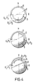
- the arrangement of the radial slot on the control disk is related to the azimuthal slots and was provided here in the axis of symmetry of the azimuthal slots. Further examples are shown in FIG. 5.
- a change in the arrangement of the radial slot means a fixed position of the light transmitter / receiver pairs (E1 / T1; E2 / T2) a rotation of the x-y coordinate cross. If, as is generally the case, you choose the x-axis horizontally and the y-axis vertically in space, you can e.g. select the position of the light transmitter / receiver pairs at 180 ° and 270 ° (Fig. 1, section B-B).
- the sensor tube must be roughly aligned (horizontal-vertical) when attached to the concentrator.
- the azimuthal slits together with the IR transmitter / receiver pairs, serve to record the direction of deviation of the sun image in x and y proportions, the location-related alignment of the mutually perpendicular coordinates being arbitrary, but usually being chosen horizontally and vertically.
- the IR receivers ensure that the x and y integrators connected downstream of the photocell, depending on the position of the control disc, either with the positive or with the incumbent signal, the absolute value thereof, depending on the position of the control disc corresponds to the emigration of the sun.
- a small electric motor M ensures the rotation of the control disc.
- the speed determines the time for a cycle, which results in 0.1 sec at 6000 rpm (100 Hz) and is sufficient for most applications. During this time the sun sets about 4 10 ⁇ 4 degrees (0.03 ') back.
- the motor M is operated with a constant voltage of 1 V, which can be obtained from the TTL supply voltage by means of a simple transistor control (see FIG. 3).
- the amplified signal is placed on two analog switches (DG 181) (S2, S4) and depending on the position of the control disc in the angular range - 90 ° to 90 ° on the x-integrator A4 and 0 ° to 180 ° to the y-integrator A5 passed on.
- DG 181 analog switches
- the inverter stage A3 inverts the signal coming from the amplifier stage, which is also in the angular range via analog switches (S1, S3) 90 ° to 270 ° to the x-integrator and 180 ° to 360 ° to the y-integrator is passed on.
- the control of the analog switch depending on the position of the control disc ensures that the subsequent integrators are fed the amplified signal and after inverting the perforated disc by 180 ° the inverted amplified signal (out of phase).
- the y-integrator receives the signal which is phase-shifted by 90 °).
- the integrators A4, A5 emit a voltage at the output, the value of which corresponds to the arithmetic sum of the instantaneous input voltages clocked by the rotation of the control disk over a specific time. During nine of the ten revolutions of a cycle, the integrators depending on the position of the control disc and the emigration of the sun image.
- sample + Hold block takes over the integration signal during the ninth revolution of the control disk, stores this signal and, while the new measuring cycle is running, sends this signal to the subsequent comparator stage (A8, A9; A10, A11) as well as the diodes D14 - 17, D18 - 21 to the commercially available speed control (tachometer control) for the two DC motors (west-east, up-down).
- the measuring time is 0.09 seconds, the time of an entire cycle 0.1 seconds.
- the output signal of the sample & hold (A6, 7) is sent to the window comparators for controlling the declination motor (A10, 11) and the azimuth motor (A8, 9).
- the polarity determines the direction of rotation of the motors via the relays (d1, d2; D3, d4).
- the speed of the motors determines the absolute magnitude of the signal, which can be coupled to a commercially available tachometer control via D18-D21 and D14-D17.
- the window comparators switch on the motors with an output signal of 1 V of the Sample + Hold. This corresponds to an emigration of the sun by 0.05 ° (3 ') with approx. 100 W / m2 irradiation (lower sensitivity limits of the sensor).
- the motors are switched off when the output signal has dropped back to 0.1 V due to the tracking of the sun (switch-off threshold of the comparators). With greater irradiation, the angular accuracy is higher (better than 0.017 °; 1 ').
- the properties of the sensor can be adapted to the respective requirements within wide limits.
- the entire arrangement described here is installed in a weatherproof tube (FIG. 1).
- the measuring device is connected to the following regulation for the two tracking motors via a multi-pole cable, which transmits both the voltage supply ( ⁇ 12V, 5V, OV) and the measured value ( ⁇ 12 V max.).
- the sensor described above has compared to the known shading systems, which basically work with a shadow on a photocell when measuring, a higher tracking accuracy (0.01 °) and a greater sensitivity to weak solar radiation.
- the optics used, in conjunction with the downstream electronics, are able to find the center of brightness in the sky and thus ensure maximum safety during tracking. Partial shadowing of the sun during cloud passage, the circumsolar radiation in high fog and haze or the slight change in the size of the sun image due to the different distance from the earth to the sun over the seasons (perihelion, aphelium) therefore do not affect the sensor.
- the sensor was successfully used for several months on a parabolic mirror test facility (concentration> 1500) to generate solar high-temperature heat (T ⁇ 800 ° - 1500 ° C).
- the concentrator is set up parallactically and is roughly adjusted at an hourly angle with a synchronous motor (1 rev / day).
- One DC motor in azimuth coupled via differential gear and another for the declination axis are used for the correction movements.
- the sensor described was coupled to the commercially available tachometer control of the two motors.
- the measured deviation from the target position was approx. 0.01 ° (0.6 '), at 350 W / m2 the deviation is approx. 0.02 ° (1.2').
- the desired angular accuracy during tracking can be adapted to the requirements over wide limits (0.01 ° - 0.1 °) by selecting the response and switch-off threshold of the window comparators.
- the senor is far cheaper than commercially available two-coordinate tracking systems, which have a much lower accuracy of approx. 0.18 ° at 1000 W / m2 irradiation.
- FIG. 6 A schematic structure of a sun concentrator with a sensor according to the invention is shown in FIG. 6: M1 and M2 are east / west or up / down tracking motors and M3 is a synchronous motor to compensate for the apparent daytime movement of the sun (1500 / min). The position shown corresponds to the south position in spring or autumn.
- the control circuit connected to the sensor and its connection to the motors M1 and M2 is not shown in the drawing.
- the spatially fixed assignment of the sensor and the device to be controlled is no longer necessary if the deflection information is fed to a central control computer.
- the sensor itself must have controllable alignment means for tracking.
- Such a sensor (which is tracked in the event of significant deviations of the light source from the optical axis while leaving the acceptance range of the sensor) can also be operated independently (independently of any device to be controlled), e.g. to detect the relative movement of a light source.
- imaging system instead of the lenses L1, L2, mirror optics or any other imaging system can be used.
- the radial slot 1 does not necessarily have an approximately linear-elongated shape, but can e.g. be triangular, in particular with the tip pointing towards the control disc center, which is expedient for a non-linear response of the device to the deflection to be detected.
Landscapes
- Physics & Mathematics (AREA)
- Electromagnetism (AREA)
- Engineering & Computer Science (AREA)
- General Physics & Mathematics (AREA)
- Radar, Positioning & Navigation (AREA)
- Remote Sensing (AREA)
- Life Sciences & Earth Sciences (AREA)
- Sustainable Development (AREA)
- Control Of Position Or Direction (AREA)
- Navigation (AREA)
- Photometry And Measurement Of Optical Pulse Characteristics (AREA)
Description
Die Erfindung bezieht sich auf eine Vorrichtung zur Ausrichtung einer in zwei Koordinaten richtungssteuerbaren Einrichtung auf eine relativ dazu bewegte Lichtquelle, wobei die Vorrichtung einen in seiner optischen Achse auf die Lichtquelle ausrichtbaren Sensor in fester räumlicher Zuordnung zur Einrichtung aufweist, der ein System (L₁, L₂) zur Erzeugung eines Bildes der Lichtquelle auf einer rotierenden lichtundurchlässigen Steuerscheibe (S) mit einem lichtdurchlässigen Radialschlitz (1) aufweist, hinter dem ein Radial-Lichtempfänger (D₁) für die durch den Radialschlitz gelangende Lichtmenge angeordnet ist,
Sie bezieht sich insbesondere auf die Nachführung von Sonnenkonzentratoren in zwei Koordinaten.The invention relates to a device for aligning a directionally controllable device in two coordinates to a light source moved relative thereto, the device having a sensor that can be aligned in its optical axis to the light source in a fixed spatial association with the device, which has a system (L₁, L₂ ) for generating an image of the light source on a rotating opaque control disc (S) with a translucent radial slot (1), behind which a radial light receiver (D₁) is arranged for the amount of light passing through the radial slot,
It relates in particular to the tracking of solar concentrators in two coordinates.
Sonnenkonzentratoren mit hohem Konzentrationsverhältnis (von 300 und mehr) müssen mit hoher Genauigkeit (besser als 0,1°) der Sonne nachgeführt werden, um mit gutem Wirkungsgrad zu arbeiten. Dabei muß die solare Strahlungsenergie möglichst zu jedem Zeitpunkt ohne Verlust vom Konzentrator zum Strahlungsempfänger gelangen. Die Systeme werden deshalb in zwei Achsen der Bewegung der Sonne über den Tag hinweg nachgeführt.Solar concentrators with a high concentration ratio (of 300 and more) must track the sun with high accuracy (better than 0.1 °) in order to work with good efficiency. The solar radiation energy must reach the radiation receiver at any time without loss from the concentrator. The systems therefore track the sun's movement throughout the day in two axes.
Prinzipiell kann diese Nachführung nach einem festen von der Sonnenbewegung abhängenden Steuerprogramm erfolgen. Da aber ohnehin Mißweisungen auftreten können durch Toleranzen in Lagern und Getrieben, ungenaue Aufstellung, Fehler der Positionsgeber (Potentiometer) bei Winkelsteuerung und durch Windbewegung, wird üblicherweise eine vom unmittelbaren Lichteinfall abhängende Nachführungssteuerung vorgesehen.In principle, this tracking can be done according to a fixed control program that depends on the movement of the sun respectively. However, since errors can occur in any case due to tolerances in bearings and gearboxes, inaccurate positioning, errors in the position transmitter (potentiometer) in the case of angle control and due to wind movement, a tracking control that is dependent on the direct incidence of light is usually provided.
Bekannte Steuerungen arbeiten mit einer Mehrzahl von lichtempfindlichen Zellen und Schattensäule für die Feineinstellung. Diese Anordnungen, die bei klarer Witterung ausreichend empfindlich arbeiten, werden in ihrer Funktion durch Hochnebel, Wolkendurchzug und Dunstbildung beeinträchtigt. Ihre Nachführgenauigkeit liegt nur bei ca. 0,2° (12'), was für höher konzentrierende Systeme nicht ausreicht.Known controls work with a plurality of light-sensitive cells and shadow columns for fine adjustment. These arrangements, which work with sufficient sensitivity in clear weather, are impaired in their function by high fog, cloud passage and haze formation. Their tracking accuracy is only approx. 0.2 ° (12 '), which is not sufficient for higher concentration systems.
Eine Anordnung zur automatischen Richtungssteuerung von Tunnelbohrmaschinen mit Hilfe eines von einem Fixpunkt ausgesandten Laserstrahls ist aus der FR-A-1 533 913 bekannt, bei der zwei mit definiertem Achsabstand auf der Bohrmaschine angeordnete Strahlempfängersysteme zur Erfassung der Winkelabweichungen vorgesehen sind, die abhängig vom ermittelten Verkantungswinkel für eine Selbstzentrierung der Bohrmaschine in die Strahlrichtung sorgen.An arrangement for automatically controlling the direction of tunnel boring machines with the aid of a laser beam emitted from a fixed point is known from FR-A-1 533 913, in which two beam receiver systems are provided with a defined center distance on the drilling machine for detecting the angular deviations which depend on the determined tilt angle ensure self-centering of the drill in the beam direction.
Dabei ist vor jedem der beiden Empfänger eine rotierende Blende mit einem offenen Sektor (z.B. 90°-Sektor) mit zugeordneter Photozelle vorgesehen, aus deren abhängig von der Verkantung moduliertem Photostrom zwei Fehlerdetektorspannungen gewonnen werden, die Servomotoren zur Selbstzentrierung steuern, wobei für die Richtungszuordnung zwei versetzte azimutale Randstreifen (180°-Bogen) mit zugeordnetem Photozellenpaar sorgen.In front of each of the two receivers, there is a rotating diaphragm with an open sector (eg 90 ° sector) with an associated photo cell, from whose dependent modulated photocurrent two error detector voltages are obtained, the servomotors for self-centering control, two offset azimuthal stripes (180 ° bend) with assigned photocell pair for the direction assignment.
Diese mit zwei Empfängersystemen arbeitende Anordnung ist relativ aufwendig und mit der modulationsabhängigen Erfassung der Verkantung nicht besonders empfindlich.This arrangement, which works with two receiver systems, is relatively complex and, with the modulation-dependent detection of the tilt, is not particularly sensitive.
Ziel der Erfindung ist daher eine Vorrichtung zur Ausrichtung einer richtungssteuerbaren Einrichtung auf eine relativ dazu bewegte Lichtquelle, die mit relativ geringem Aufwand hohe Empfindlichkeiten erreicht. Dabei ist insbesondere die Nachführung von Sonnenkonzentratoren von Interesse, die mit großer Genauigkeit unabhängig von Dunstbildung u.dgl. das sichtbare Strahlungszentrum am Himmel findet und der Ausrichtung zugrundeliegt.The aim of the invention is therefore a device for aligning a direction-controllable device to a light source moved relative thereto, which achieves high sensitivities with relatively little effort. The tracking of solar concentrators is of particular interest here, and the like with great accuracy regardless of haze formation. finds the visible center of radiation in the sky and underlies the alignment.
Die zu diesem Zweck entwickelte erfindungsgemäße Vorrichtung der eingangs genannten Art ist dadurch gekennzeichnet, daß der Sensor einen Sensortubus mit dem System (L₁, L₂) aufweist, daß die Steuerscheibe größer ist als die vom schwankenden Bild der Lichtquelle überstrichene Fläche, daß der lichtdurchlässige Radialschlitz (1) nach außen bis zum Rand dieser Fläche und nach innen bis an die Peripherie des zentrierten Bildes der Lichtquelle reicht und daß der Sensor außerhalb des Radialschlitzes zwei konzentrische lichtdurchlässige halbkreisförmige Azimutalschlitze (2, 3) mit unterschiedlichem Radius und mit je einem zugeordneten ortsfesten Lichtsender (E₁, E₂) aufweist, desen Licht durch den jeweiligen Azimutalschlitz (2, 3) auf einen gegenüberliegenden ortsfesten Azimutal-Lichtempfänger (T₁, T₂) fällt, wobei für senkrecht aufeinander stehende Nachführungsachsen der richtungssteuerbaren Einrichtung stets ein Sender/ Empfänger-Paar (E₁/T₁) in der Mitte des zugehörigen Azimutalschlitzes (2) steht, wenn sich das zweite Sender/ Empfänger-Paar (E₂, T₂) am Anfang seines zugehörigen Azimutalschlitzes (3) befindet, wobei der Sensortubus zusammen mit den darin ortsfesten Sender/Empfänger-Paaren (E₁/T₁, E₂, T₂) eine auf der richtungssteuerbaren Einrichtung dreh-justierbare Halterung aufweist, die eine anfängliche Ausrichtung des Radialschlitzes (1) in die Richtung einer der beiden Koordinatenachsen gestattet, wenn eines der Sender/Empfänger-Paare am Anfang des zugehörigen Azimutalschlitzes (2) steht, und wobei die Vorrichtung einen Nachführungsmotor oder Nachführungsmotoren und eine elektrische Schaltung aufweist, um die Drehzahl des Motors oder der Motoren proportional der Größe der durch den Radiallichtempfänger (D₁) erkannten Abweichung der Lichtquelle und die Drehrichtung des Motors oder der Motoren entsprechend der durch die Azimutallichtempfänger (T₁, T₂) erkannten Abweichungsrichtung der Lichtquelle zu steuern.The device of the type mentioned at the outset, which was developed for this purpose, is characterized in that the sensor has a sensor tube with the system (L₁, L₂), that the control disk is larger than the area covered by the fluctuating image of the light source, that the translucent radial slot ( 1) outwards to the edge of this surface and inwards to the periphery of the centered image of the light source and that the sensor outside the radial slot has two concentric translucent semicircular azimuthal slots (2, 3) with different radius and each with an assigned fixed light transmitter ( E₁, E₂), whose light falls through the respective azimuthal slit (2, 3) onto an opposite fixed azimuthal light receiver (T₁, T₂), with the directionally controllable tracking axes perpendicular to one another Device is always a transmitter / receiver pair (E₁ / T₁) in the middle of the associated azimuth slot (2) when the second transmitter / receiver pair (E₂, T₂) is at the beginning of its associated azimuth slot (3), the Sensor tube together with the stationary transmitter / receiver pairs (E₁ / T₁, E₂, T₂) has a rotation-adjustable holder on the directionally controllable device, which allows an initial alignment of the radial slot (1) in the direction of one of the two coordinate axes if one of the transmitter / receiver pairs at the beginning of the associated azimuthal slot (2), and wherein the device has a tracking motor or tracking motors and an electrical circuit to the speed of the motor or motors proportional to the size of the detected by the radial light receiver (D₁) Deviation of the light source and the direction of rotation of the motor or motors corresponding to that by the azimuthal light length (T₁, T₂) to detect the direction of deviation of the light source.
Bei dieser Anordnung wird lediglich ein optisches System angewandt und eine hohe Empfindlichkeit dadurch erreicht, daß ausgehend von völliger Zentrierung mit einem Signal = 0 bei einer Abweichung von der Zentrierung ein Signal proportional zur Auslenkung erfaßt wird. Das zur Auslenkung proportionale Steuersignal für die Lagekorrektur, mit dessen Hilfe der Motor umso schneller läuft, je weiter die Auslenkung ist, hilft Regelschwingungen zu vermeiden.In this arrangement, only an optical system is used and a high sensitivity is achieved in that, starting from complete centering with a signal = 0 and a deviation from the centering, a signal proportional to the deflection is detected. The control signal for the position correction, which is proportional to the deflection and with the help of which the motor runs the faster the further the deflection, helps to avoid control vibrations.
Als bilderzeugendes System dient erfindungsgemäß insbesondere ein Linsensystem, das im Falle der Nachführung von Sonnenkonzentratoren ein Bild der Sonne auf der Steuerscheibe erzeugt.According to the invention, a lens system is used in particular as the image-generating system, which generates an image of the sun on the control disk when tracking solar concentrators.
Bei dieser Vorrichtung wird durch den Radialschlitz hindurch eine der Auslenkung entsprechende Lichtmenge empfangen, während mit Hilfe der Azimutalschlitze und Sender/Empfänger-Paare die Auslenkungsrichtung erfaßt wird.In this device, a quantity of light corresponding to the deflection is received through the radial slit, while the direction of deflection is detected with the aid of the azimuthal slits and transmitter / receiver pairs.
Die elektronische Steuerschaltung umfaßt einen Integralregler, der ein - bei Annäherung an die Sollposition kontinuierlich geringer werdendes - Signal erzeugt, das entsprechend der Abweichungsrichtung in ein x- und ein y-Signal aufgeteilt ist.Diese Regelsignale dienen zur Nachführung in zwei Achsen mit Hilfe von zwei regelbaren Gleichstrommotoren oder auch nur eines Nachführungsmotors. Die Regelsignale können auch für den notwendigen Soll-Ist-Wert-Vergleich bei komputergesteuerten Konzentratoren verwendet werden.The electronic control circuit includes an integral controller, which generates a signal that decreases continuously as the target position is approached and is divided into an x and a y signal according to the direction of deviation. These control signals are used for tracking in two axes with the help of two controllable DC motors or just one tracking motor. The control signals can also be used for the necessary target / actual value comparison in computer-controlled concentrators.
Die Vorrichtung kann verwendet werden für das Nachführen von
- parabolischen oder sphärischen Konzentratoren (parabolic dish) nach dem Solar-Farm-Prinzip
- Heliostaten oder Heliostatenfeldern für Solar-Tower-Anlagen (
erforderliche Genauigkeit 0,02° - 0,05°) - Versuchsanlagen für solare Hochtemperaturerzeugung mit Konzentrationsverhältnissen über 1000
- parabolic or spherical concentrators (parabolic dish) according to the solar farm principle
- Heliostats or heliostat fields for solar tower systems (required accuracy 0.02 ° - 0.05 °)
- Test plants for solar high temperature generation with concentration ratios over 1000
Die Hauptelemente der Vorrichtung werden im nachfolgenden mehr im einzelnen unter Bezugnahme auf die angefügten Zeichnungen erläutert; es zeigen im einzelnen:
- Fig. 1
- den Sensortubus mit zwei Linsen,
- Fig. 2
- eine Steuerscheibe für den Sensor,
- Fig. 3 u. 7
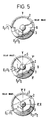
- einen Schaltplan für die Sensorelektronik,
- Fig. 4 u. 5
- Beispiele für mögliche Positionen der Azimutalschlitze und des Radialschlitzes auf der Steuerscheibe und
- Fig. 6
- den Aufbau eines Sonnenkonzentrators mit erfindungsgemäßem Sensor.
- Fig. 1
- the sensor tube with two lenses,
- Fig. 2
- a control disc for the sensor,
- Fig. 3 u. 7
- a circuit diagram for the sensor electronics,
- Fig. 4 u. 5
- Examples of possible positions of the azimuthal slots and the radial slot on the control disk and
- Fig. 6
- the construction of a solar concentrator with the sensor according to the invention.
Der in Figur 1 gezeigte Sensortubus enthält zwei Linsen L₁ und L₂ (bikonvexe achromatische Linsen) mit den Brennweiten f₁ = 200 mm und f₂ = 16 mm. Damit ergibt sich eine optische Gesamtbrennweite von ca. 2 m bei einer reduzierten Baulänge von ca. 40 cm. Mit einer (nicht gezeigten) Irisblende bei A kann die Sensorempfindlichkeit eingestellt werden.The sensor tube shown in Figure 1 contains two lenses L₁ and L₂ (biconvex achromatic lenses) with the focal lengths f₁ = 200 mm and f₂ = 16 mm. This results in an overall optical focal length of approx. 2 m with a reduced overall length of approx. 40 cm. The sensor sensitivity can be adjusted with an iris diaphragm at A (not shown).
Damit wird ein Sonnenbild von ca. 2 cm 0̸ auf der Steuerscheibe (aus Plexiglas) scharf abgebildet, die einen radialen Schlitz 1 von 20 mm Länge und 2 mm Breite (bestimmt die Ortsauflösung) und zwei azimutale oder halbkreisförmige Schlitze 2, 3 in einem durch Schraffur angedeuteten Lichtundurchlässigen Belag aufweist (s. Figur 2). Der Radialschlitz 1, der 10 mm vom Zentrum der Scheibe entfernt ist, grenzt damit unmittelbar an das genau zentrierte Sonnenbild an.Thus, a sun image of approx. 2 cm 0̸ is sharply depicted on the control disc (made of plexiglass), which has a
Die Steuerscheibe rotiert mit ca. 100 Hz, wobei während einer Umdrehung das (bei Sollposition dunkle) Umfeld des Sonnenbildes vom radialen Schlitz abgetastet wird. Bei Abweichung des Sonnenbildes (d.h. der optischen Achse des Nachführungssystems) von der Sollposition erfaßt dieser Schlitz ein mehr oder minder großes sichelförmiges Segment des hellen Sonnenbildes, dessen Licht durch eine Streuscheibe (Maratascheibe) auf die ortsfeste Fotozelle D₁ (BPW 34 in Fig. 3) fällt, deren Ausgangssignal dem Absolutbetrag der Abweichung entspricht.The control disc rotates at approx. 100 Hz, the area around the sun image (which is dark at the target position) being scanned by the radial slot during one revolution. If the sun image (ie the optical axis of the tracking system) deviates from the desired position, this slit detects a more or less large crescent-shaped segment of the bright sun image, the light of which through a diffusion disc (Marata disc) onto the stationary photocell D 1 (BPW 34 in Fig. 3) falls, whose output signal corresponds to the absolute amount of the deviation.
Die azimutalen Schlitze 2 und 3 am Rande der Steuerscheibe ergänzen einander zu 360°. (Weitere Beispiele sind in Fig. 4 angegeben). Zwei zugeordnete Paare von ortsfesten IR-Sendern/-Empfängern (E₁/T₁; E₂/T₂), die um 90° versetzt angebracht sind, bilden jeweils eine Lichtschranke, über welche die Stellung der Steuerscheibe im Verlaufe einer Vollumdrehung erkannt wird. Der Ausgang dieser Empfänger wird für die richtungsbezogene Steuerung der Nachführungsorgane abhängig von der durch den Radialschlitz erfaßten Auslenkung des Sonnenbildes (von der Sollposition) ausgenutzt.The
Die Anordnung des Radialschlitzes auf der Steuerscheibe steht in Beziehung zu den Azimutalschlitzen und wurde hier in der Symmetrieachse der Azimutalschlitze vorgesehen. Weitere Beispiele gehen aus Fig. 5 hervor. Eine Veränderung der Anordnung des Radialschlitzes bedeutet bei fester Position der Lichtsender/-empfängerpaare (E₁/T₁; E₂/T₂) eine Drehung des x-y-Koordinatenkreuzes. Wählt man, wie allgemein üblich, die x-Achse horizontal und die y-Achse vertikal im Raum, so läßt sich z.B. die Position der Lichtsender/-empfängerpaare zu 180° und 270° wählen (Fig. 1, Schnitt B-B). Der Sensortubus ist bei Anbau an den Konzentrator entsprechend (grob) auszurichten (Horizontale-Vertikale).The arrangement of the radial slot on the control disk is related to the azimuthal slots and was provided here in the axis of symmetry of the azimuthal slots. Further examples are shown in FIG. 5. A change in the arrangement of the radial slot means a fixed position of the light transmitter / receiver pairs (E₁ / T₁; E₂ / T₂) a rotation of the x-y coordinate cross. If, as is generally the case, you choose the x-axis horizontally and the y-axis vertically in space, you can e.g. select the position of the light transmitter / receiver pairs at 180 ° and 270 ° (Fig. 1, section B-B). The sensor tube must be roughly aligned (horizontal-vertical) when attached to the concentrator.
Die azimutalen Schlitze dienen zusammen mit den IR-Sender/-Empfängerpaaren der Erfassung der Abweichungsrichtung des Sonnenbildes in x- und y-Anteilen, wobei die standortbezogene Ausrichtung der aufeinander senkrechten Koordinaten beliebig wählbar ist, üblicherweise jedoch horizontal und vertikal gewählt wird. Dabei sorgen die IR-Empfänger dafür, daß die der Photozelle nachgeschalteten x- und y-Integratoren gemäß der laufenden Hell-Dunkelschaltung je nach Stellung der Steuerscheibe entweder mit dem positiven oder mit dem invertrierten Signal, dessen Absolutbetrag der Auswanderung der Sonne entspricht, beaufschlagt werden.The azimuthal slits, together with the IR transmitter / receiver pairs, serve to record the direction of deviation of the sun image in x and y proportions, the location-related alignment of the mutually perpendicular coordinates being arbitrary, but usually being chosen horizontally and vertically. The IR receivers ensure that the x and y integrators connected downstream of the photocell, depending on the position of the control disc, either with the positive or with the incumbent signal, the absolute value thereof, depending on the position of the control disc corresponds to the emigration of the sun.
Ein kleiner Elektromotor M (Graupner, Micro T05, o.a.) sorgt für die Rotation der Steuerscheibe. Die Drehzahl bestimmt die Zeit für einen Zyklus, der sich zu 0,1 sec bei 6000 U/min (100 Hz) ergibt und für die meisten Anwendungen ausreicht. In dieser Zeit legt die Sonne ca. 4 . 10⁻⁴ Grad (0,03') zurück. Der Motor M wird mit einer konstanten Spannung von 1 V betrieben, die mittels einer einfachen Transistorregelung aus der TTL-Versorgungsspannung gewonnen werden kann (s. Fig. 3).A small electric motor M (Graupner, Micro T05, etc.) ensures the rotation of the control disc. The speed determines the time for a cycle, which results in 0.1 sec at 6000 rpm (100 Hz) and is sufficient for most applications. During this time the sun sets about 4 10⁻⁴ degrees (0.03 ') back. The motor M is operated with a constant voltage of 1 V, which can be obtained from the TTL supply voltage by means of a simple transistor control (see FIG. 3).
Bei der Abtastung der Umgebung des Sollwertes (Ausgangssignal Null) durch die Steuerscheibe werden alle im Umkreis vom Sollwert vorhandenen Lichtstrahlen (max. ± 0,75° von der Bildmitte) eines vom Sollwert abweichenden Sonnenbildes von der im Kurzschlußbetrieb arbeitenden Fotozelle D₁ empfangen (s. Fig. 3) und das von der Zelle gelieferte Signal durch Operationsverstärker (A₁, A₂, A₃) verarbeitet, und zwar wird im Strom-Spannungswandler A₁ der Ausgangsstrom der Fotozelle in eine proportionale Spannung umgewandelt. Die nachfolgende Verstärkerstufe A₂ wurde auf 100-fache Verstärkung eingestellt. Das verstärkte Signal wird auf zwei Analogschalter (DG 181) gelegt (S2, S4) und je nach Stellung der Steuerscheibe im Winkelbereich
- 90 ° bis 90 ° an den x-Integrator A4
und
0 ° bis 180 ° an den y-Integrator A5
weitergegeben.When scanning the surroundings of the setpoint (output signal zero) through the control disk, all light rays present in the vicinity of the setpoint (max. ± 0.75 ° from the center of the picture) of a sun image deviating from the setpoint are received by the photocell D₁ working in short-circuit mode (see. Fig. 3) and the signal supplied by the cell processed by operational amplifiers (A₁, A₂, A₃), namely in the current-voltage converter A₁ the output current of the photocell is converted into a proportional voltage. The subsequent amplifier stage A₂ was set to 100 times the gain. The amplified signal is placed on two analog switches (DG 181) (S2, S4) and depending on the position of the control disc in the angular range
- 90 ° to 90 ° on the x-integrator A4
and
0 ° to 180 ° to the y-integrator A5
passed on.
Die Inverterstufe A3 invertiert das aus der Verstärkerstufe kommende Signal, das ebenfalls über Analogschalter (S1, S3) im Winkelbereich
90 ° bis 270 ° an den x-Integrator
und
180 ° bis 360 ° an den y-Integrator
weitergegeben wird.The inverter stage A3 inverts the signal coming from the amplifier stage, which is also in the angular range via analog switches (S1, S3)
90 ° to 270 ° to the x-integrator
and
180 ° to 360 ° to the y-integrator
is passed on.
Die von der Stellung der Steuerscheibe (winkelabhängige) Steuerung der Analogschalter sorgt dafür, daß den nachfolgenden Integratoren also einmal das verstärkte und nach einer Drehung der Lochscheibe um 180 ° das invertierte verstärkte Signal (phasenverschoben) zugeführt wird. Der y-Integrator erhält das um 90 ° phasenverschobene Signal).The control of the analog switch depending on the position of the control disc (angle-dependent) ensures that the subsequent integrators are fed the amplified signal and after inverting the perforated disc by 180 ° the inverted amplified signal (out of phase). The y-integrator receives the signal which is phase-shifted by 90 °).
Die Integratoren A4, A5 geben am Ausgang eine Spannung ab, deren Wert der arithmetischen Summe der momentanen, durch die Drehung der Steuerscheibe getakteten Eingangsspannungen über eine bestimmte Zeit entspricht. Während neun der zehn Umdrehungen eines Zyklus werden die Integratoren entsprechend der Stellung der Steuerscheibe und der Auswanderung des Sonnenbildes ge- bzw. entladen.The integrators A4, A5 emit a voltage at the output, the value of which corresponds to the arithmetic sum of the instantaneous input voltages clocked by the rotation of the control disk over a specific time. During nine of the ten revolutions of a cycle, the integrators depending on the position of the control disc and the emigration of the sun image.
Der nachfolgende "Sample + Hold" Baustein (A6, A7) übernimmt das Integrationssignal während der neunten Umdrehung der Steuerscheibe, speichert dieses Signal und gibt, während der neue Meßzyklus läuft, dieses Signal an die nachfolgende Komparatorstufe (A8, A9; A10, A11) sowie über die Dioden D14 - 17, D18 - 21 an die handelsübliche Drehzahlregelung (Tachoregelung) für die beiden Gleichstrommotoren (West-Ost, Auf-Ab) ab.The following "Sample + Hold" block (A6, A7) takes over the integration signal during the ninth revolution of the control disk, stores this signal and, while the new measuring cycle is running, sends this signal to the subsequent comparator stage (A8, A9; A10, A11) as well as the diodes D14 - 17, D18 - 21 to the commercially available speed control (tachometer control) for the two DC motors (west-east, up-down).
Ein Zähler (SN 7490) und ein Dekoder (SN 7442) in Verbindung mit einem Schmitt-Trigger, der an die x-Steuerung angeschlossen ist, liefert einen Takt, der es gestattet, den Sample & Hold während des 9. Zyklus der Lochscheibe mit S₇ und S₈ zu laden und den Integrator während des 10. Umlaufes der Lochscheibe mit S₅ und S₆ zu entladen (System-Reset). Die Meßzeit beträgt damit 0,09 Sekunden, die Zeit eines gesamten Zyklus 0,1 Sekunden.A counter (SN 7490) and a decoder (SN 7442) in connection with a Schmitt trigger, which is connected to the x-control, delivers a cycle that allows the Sample & Hold to be carried out during the 9th cycle of the perforated disc Load S₇ and S₈ and discharge the integrator with S₅ and S₆ during the 10th revolution of the perforated disc (system reset). The measuring time is 0.09 seconds, the time of an entire cycle 0.1 seconds.
Das Ausgangssignal des Sample & Hold (A6, 7) gelangt auf die Fensterkomparatoren für die Steuerung des Deklinationsmotors (A10, 11) und des Azimuthmotors (A8, 9). Die Polarität bestimmt über die Relais (d₁, d₂; D₃, d₄) die Drehrichtung der Motoren. Die Drehzahl der Motoren bestimmt sich über die absolute Größe des Signals, das über D18-D21 und D14-D17 an eine handelsübliche Tachoregelung angekoppelt werden kann.The output signal of the sample & hold (A6, 7) is sent to the window comparators for controlling the declination motor (A10, 11) and the azimuth motor (A8, 9). The polarity determines the direction of rotation of the motors via the relays (d₁, d₂; D₃, d₄). The speed of the motors determines the absolute magnitude of the signal, which can be coupled to a commercially available tachometer control via D18-D21 and D14-D17.
Die Fensterkomperatoren schalten bei einem Ausgangssignal von 1 V des Sample + Hold die Motoren ein. Das entspricht einer Auswanderung der Sonne um 0,05 ° (3') bei ca. 100 W/m² Einstrahlung (untere Empfindlichkeitsgrenzen des Sensors). Die Motoren werden abgeschaltet, wenn das Ausgangssignal aufgrund der Verfolgung der Sonne wieder auf 0,1 V zurückgegangen ist (Abschaltschwelle der Komparatoren). Bei größerer Einstrahlung ist die Winkelgenauigkeit höher (besser als 0,017 °; 1'). Durch andere Einstellung der Schaltelemente lassen sich die Eigenschaften des Sensors in weiten Grenzen den jeweiligen Anforderungen anpassen.The window comparators switch on the motors with an output signal of 1 V of the Sample + Hold. This corresponds to an emigration of the sun by 0.05 ° (3 ') with approx. 100 W / m² irradiation (lower sensitivity limits of the sensor). The motors are switched off when the output signal has dropped back to 0.1 V due to the tracking of the sun (switch-off threshold of the comparators). With greater irradiation, the angular accuracy is higher (better than 0.017 °; 1 '). By changing the switching elements, the properties of the sensor can be adapted to the respective requirements within wide limits.
Die gesamte hier beschriebene Anordnung ist in einen Tubus (Fig. 1) wetterfest eingebaut. Die Meßeinrichtung ist mit der nachfolgenden Regelung für die beiden Nachführungsmotoren über ein mehrpoliges Kabel verbunden, das sowohl die Spannungsversorgung (± 12V, 5V, OV) als auch den Meßwert (± 12 V max.) überträgt.The entire arrangement described here is installed in a weatherproof tube (FIG. 1). The measuring device is connected to the following regulation for the two tracking motors via a multi-pole cable, which transmits both the voltage supply ( ± 12V, 5V, OV) and the measured value ( ± 12 V max.).
Der vorstehend beschriebene Sensor hat gegenüber den bekannten Abschattungssystemen, die prinzipiell bei Meßweisung mit Schattenwurf auf eine Fotozelle arbeiten, eine höhere Nachführgenauigkeit (0,01 °) sowie eine größere Empfindlichkeit bei schwacher Solarstrahlung. Die verwendete Optik ist in Verbindung mit der nachgeschalteten Elektronik in der Lage, das Helligkeitszentrum am Himmel zu finden und damit höchste Sicherheit bei der Nachführung zu gewährleisten. Teilabschattung der Sonne bei Wolkendurchzug, die Zirkumsolarstrahlung bei Hochnebel und Dunst oder die geringfügige Änderung der Größe des Sonnenbildes aufgrund der unterschiedlichen Entfernung Erde - Sonne über die Jahreszeiten (Perihel, Aphel) beeinflussen deshalb den Sensor nicht.The sensor described above has compared to the known shading systems, which basically work with a shadow on a photocell when measuring, a higher tracking accuracy (0.01 °) and a greater sensitivity to weak solar radiation. The optics used, in conjunction with the downstream electronics, are able to find the center of brightness in the sky and thus ensure maximum safety during tracking. Partial shadowing of the sun during cloud passage, the circumsolar radiation in high fog and haze or the slight change in the size of the sun image due to the different distance from the earth to the sun over the seasons (perihelion, aphelium) therefore do not affect the sensor.
Der Sensor wurde mehrere Monate an einer Parabolspiegel-Versuchsanlage (Konzentration >1500) zur Erzeugung solarer Hochtemperaturwärme (T ∼ 800 ° - 1500 °C) mit Erfolg eingesetzt. Der Konzentrator ist parallaktisch aufgestellt und wird im Stundenwinkel grob mit einem Synchronmotor (1 U/Tag) nachgeführt. Für die Korrekturbewegungen wird ein über Differentialgetriebe angekoppelter Gleichstrommotor im Azimuth und ein weiterer für die Deklinationsachse verwendet. Der beschriebene Sensor wurde an die handelsübliche Tachoregelung der beiden Motoren angekoppelt. Bei einer solaren Einstrahlung von 900 W/m² betrug die gemessene Abweichung von der Sollposition ca. 0,01° (0,6'), bei 350 W/m² liegt die Abweichung bei ca. 0,02° (1,2'). Diese Abweichungen wurden mit einem parallel zum Sensor ausgerichteten Präzisionsfernrohr mit Strichplatte registriert.The sensor was successfully used for several months on a parabolic mirror test facility (concentration> 1500) to generate solar high-temperature heat (T ∼ 800 ° - 1500 ° C). The concentrator is set up parallactically and is roughly adjusted at an hourly angle with a synchronous motor (1 rev / day). One DC motor in azimuth coupled via differential gear and another for the declination axis are used for the correction movements. The sensor described was coupled to the commercially available tachometer control of the two motors. At a solar radiation of 900 W / m² the measured deviation from the target position was approx. 0.01 ° (0.6 '), at 350 W / m² the deviation is approx. 0.02 ° (1.2'). These deviations were registered with a precision telescope with a graticule aligned parallel to the sensor.
Regelschwingungen des Systems wurden nicht beobachtet. Die gewünschte Winkelgenauigkeit bei der Nachführung läßt sich über weite Grenzen (0,01° - 0,1°) durch Wahl der Ansprech- und Abschaltschwelle der Fensterkomparatoren den Anforderungen anpassen.Control vibrations of the system were not observed. The desired angular accuracy during tracking can be adapted to the requirements over wide limits (0.01 ° - 0.1 °) by selecting the response and switch-off threshold of the window comparators.
Der Sensor ist durch Verwendung üblicher Bauteile weit preiswerter als handelsübliche Zweikoordinanten-Nachführungen, die eine wesentlich geringere Genauigkeit von ca. 0,18° bei 1000 W/m² Einstrahlung aufweisen.Thanks to the use of conventional components, the sensor is far cheaper than commercially available two-coordinate tracking systems, which have a much lower accuracy of approx. 0.18 ° at 1000 W / m² irradiation.
Ein schematischer Aufbau eines Sonnenkonzentrators mit erfindungsgemäßem Sensor ist in Fig. 6 gezeigt: M1 und M2 sind ost/west- bzw. auf/ab-Nachführungsmotoren und M3 ist ein Synchronmotor zum Ausgleich der scheinbaren Tagesbewegung der Sonne (1500/Min). Die gezeigte Stellung entspricht der Südstellung im Frühling oder Herbst. Die an den Sensor anschliessende Steuerschaltung und deren Verbindung zu den Motoren M1 und M2 ist in Zeichnung nicht dargestellt.A schematic structure of a sun concentrator with a sensor according to the invention is shown in FIG. 6: M1 and M2 are east / west or up / down tracking motors and M3 is a synchronous motor to compensate for the apparent daytime movement of the sun (1500 / min). The position shown corresponds to the south position in spring or autumn. The control circuit connected to the sensor and its connection to the motors M1 and M2 is not shown in the drawing.
Selbstverständlich ist die räumlich feste Zuordnung von Sensor und zu steuernder Vorrichtung dann nicht mehr notwendig, wenn die Auslenkungsinformation einem zentralen Steuerkomputer zugeführt wird. In diesem Falle, muß allerdings der Sensor selbst steuerbare Ausrichtungsmittel zur Nachführung aufweisen. Ein solcher (insbesondere bei erherblichen Abweichungen der Lichtquelle von der optischen Achse unter Verlassen des Akzeptanzbereichs des Sensors nachgeführter) Sensor kann auch selbständig (unabhängig von jeder zu steuernden Vorrichtung) betrieben werden, um z.B. die Relativbewegung einer Lichquelle zu erfassen.Of course, the spatially fixed assignment of the sensor and the device to be controlled is no longer necessary if the deflection information is fed to a central control computer. In this case, however, the sensor itself must have controllable alignment means for tracking. Such a sensor (which is tracked in the event of significant deviations of the light source from the optical axis while leaving the acceptance range of the sensor) can also be operated independently (independently of any device to be controlled), e.g. to detect the relative movement of a light source.
Als Abbildungssystem kann statt der Linsen L₁, L₂, eine Spiegeloptik oder jedes andere Abbildungssystem verwendet werden.As an imaging system, instead of the lenses L₁, L₂, mirror optics or any other imaging system can be used.
Der Radialschlitz 1 hat nicht notwendigerweise eine etwa linear-längliche Form, sondern kann z.B. dreieckig sein, insbesondere mit zum Steuerscheibenzentrum weisender Spitze, was für ein nicht lineares Ansprechen der Vorrichtung auf die zu erfassende Auslenkung zweckmäßig ist.The
Claims (8)
- A means of aligning a device, which is directionally controllable with respect to two coordinates, with a light source which is moved in relation to it, wherein the means has a sensor, the optical axis of which can be aligned with the light source, in a fixed spatial relationship with the device, which device has a system (L₁, L₂) for producing an image of the light source on a rotating opaque control disc (S) with a transparent radial slit (1), behind which is disposed a radial light receiver (D₁) for the amount of light passing through the radial slit, characterised in that the sensor has a sensor tube body with the system (L₁, L₂), that the control disc is larger than the area covered by the variable image of the light source, that the transparent radial slit (1) extends outwards as far as the edge of this area and extends inwards as far as the periphery of the centred image of the light source, and that outside the radial slit the sensor has two concentric transparent semicircular azimuthal slits (2, 3) with different radii, each with an associated fixed light transmitter (E₁, E₂), the light from which falls on an opposite fixed azimuthal light receiver (T₁, T₂) via the respective azimuthal slit (2, 3), wherein, for tracking axes of the directionally controllable device which are at right angles to each other, one transmitter/receiver pair (E₁/T₁) is always in the centre of the associated azimuthal slit (2) when the second transmitter/receiver pair (E₂, T₂) is located at the start of its associated azimuthal slit (3), wherein the sensor tube body, together with the transmitter/receiver pairs (E₁/T₁, E₂, T₂) fixed within it, has a rotationally adjustable mounting on the directionally controllable device, which mounting permits an initial alignment of the radial slit (1) in the direction of one of the two coordinate axes when one of the transmitter/receiver pairs is at the start of the associated azimuthal slits (2), and wherein the means has a tracking motor or tracking motors, and an electrical circuit to control the rotational speed of the motor or motors in proportion to the magnitude of the deviation of the light source perceived by the radial light receiver (D₁), and to control the direction of rotation of the motor or motors corresponding to the direction of deviation of the light source perceived by the azimuthal light receivers (T₁, T₂).
- A means according to Claim 1, characterised in that the radial slit (1) is disposed on the axis of symmetry of at least one of the azimuthal slits (2, 3) or is displaced by a whole multiple of 90° with respect to it.
- A means according to Claim 2, characterised in that the azimuthal slits (2, 3) are externally adjacent to the radial slit and complement one another to form a complete circle, and that the radial slit (1) lies on the common axis of symmetry of the azimuthal slits.
- A means according to any one of the preceding Claims, characterised in that the diameter of the control disc (S) corresponds to three times the diameter of the solar image enlarged by the widths of the azimuthal slits, and the radial slit (1) adjoining the periphery of the centred solar image has a length of one solar image diameter.
- A means according to one of the preceding Claims, characterized in that the radial receiver (D₁) is disposed fixed behind a disc (Marata disc).
- A means according to one of the preceding Claims, characterized in that the electrical circuit comprises at least one integrator for each of the x and y coordinate axes, for the proportional summation of the signal supplied by the receiver (D₁) behind the radial slit (1) depending on the signals from the transmitter/receiver pairs (E₁/T₁, E₂/T₂) over a selectable number of control disc rotations, wherein the x or y integration signal then determines the rotational speed and the direction of rotation of the associated motor.
- A means of detecting the relative motion of a light source, characterised by the features of Claim 1, wherein the electrical circuit is used for recording the path of the light source instead of driving tracking motors.
- A means according to Claim 6 or 7, characterised in that the electrical circuit comprises an analogue portion, which amplifies and inverts the electrical signals from the radial receiver (D₁), and a digital portion, which activates the subsequent integrators for the two directions of the two coordinate control system according to the position of the rotating control disc (S) correctly in proportion to the positive or inverted signals for a definite, selectable number of rotations of the control disc, sends the integrated signal to two subsequent sample and hold components (one for each direction) during a further rotation, and re-initialises or short-circuits the integrators during the next rotation to accept the following signal cycle, and in the meantime the sample and hold components send the control signal- to a subsequent comparator circuit which determines the response threshold of the tracking motors and their direction of rotation, and to the electronic speed control system of the motors;- or to a computer for recording the path of the light source.
Applications Claiming Priority (2)
| Application Number | Priority Date | Filing Date | Title |
|---|---|---|---|
| DE19843422813 DE3422813A1 (en) | 1984-06-20 | 1984-06-20 | OPTO-ELECTRONIC SENSOR FOR ADJUSTING SUN CONCENTRATORS |
| DE3422813 | 1984-06-20 |
Publications (3)
| Publication Number | Publication Date |
|---|---|
| EP0166352A2 EP0166352A2 (en) | 1986-01-02 |
| EP0166352A3 EP0166352A3 (en) | 1987-07-22 |
| EP0166352B1 true EP0166352B1 (en) | 1992-09-09 |
Family
ID=6238775
Family Applications (1)
| Application Number | Title | Priority Date | Filing Date |
|---|---|---|---|
| EP85107475A Expired - Lifetime EP0166352B1 (en) | 1984-06-20 | 1985-06-15 | Arrangement for pointing a directable device towards a light source |
Country Status (5)
| Country | Link |
|---|---|
| US (1) | US4612488A (en) |
| EP (1) | EP0166352B1 (en) |
| JP (1) | JPS6168613A (en) |
| DE (2) | DE3422813A1 (en) |
| IL (1) | IL75570A (en) |
Families Citing this family (21)
| Publication number | Priority date | Publication date | Assignee | Title |
|---|---|---|---|---|
| DE3525065A1 (en) * | 1985-07-13 | 1987-01-22 | Abdul Whab H Nasrat | Tracking device to permit a solar energy receiver to track the sun |
| GB8724345D0 (en) * | 1987-10-16 | 1987-11-18 | Ortlieb J F | Chair for sunbathing |
| FR2639741A1 (en) * | 1988-11-30 | 1990-06-01 | Massiera Louis | Portable diary with audible information recovery |
| DE4306656A1 (en) * | 1993-03-03 | 1993-12-16 | Georg Linckelmann | Automatic sun tracking appts. - has solar panels set at angles on block and with opposite polarities to generate control voltage characteristic |
| US5893608A (en) * | 1997-04-28 | 1999-04-13 | Cravenor; William | Sun-tracking chair |
| ATE212259T1 (en) * | 1997-06-20 | 2002-02-15 | Luciano Gasparini | BENDING PRESS |
| DE10007120B4 (en) * | 2000-02-17 | 2007-04-12 | LFK Lenkflugkörpersysteme GmbH | Current regulation of permanent-magnet synchronous motors for guided missiles with electromechanical rudder actuator |
| AT413892B (en) * | 2000-07-06 | 2006-07-15 | Kuzelka Andreas | SONNENSTANDSNACHFÜHRUNGSSYSTEM |
| US6704607B2 (en) | 2001-05-21 | 2004-03-09 | The Boeing Company | Method and apparatus for controllably positioning a solar concentrator |
| US20090261810A1 (en) * | 2008-04-22 | 2009-10-22 | Solfocus, Inc. | Simulator system and method for measuring current voltage characteristic curves of a solar concentrator |
| WO2009145266A1 (en) * | 2008-05-28 | 2009-12-03 | シャープ株式会社 | Tracking type solar power generation system, and tracking control method and tracking discrepancy correcting method for the tracking type solar power generation system |
| GB2462107A (en) * | 2008-07-24 | 2010-01-27 | Peter Brown | Solar collector comprising lenses |
| US20100018518A1 (en) * | 2008-07-24 | 2010-01-28 | Mcdonald Mark | Determination of solar tracking error |
| US7895017B2 (en) * | 2008-07-24 | 2011-02-22 | Solfocus, Inc. | System to increase SNR of CPV-generated power signal |
| US20100018519A1 (en) * | 2008-07-24 | 2010-01-28 | Mcdonald Mark | Fault monitoring based on solar tracking error |
| US8598833B2 (en) * | 2009-12-11 | 2013-12-03 | Sntech Inc. | Electrically communtated motor with data communication device |
| US9893223B2 (en) | 2010-11-16 | 2018-02-13 | Suncore Photovoltaics, Inc. | Solar electricity generation system |
| US9127861B2 (en) | 2011-10-31 | 2015-09-08 | Solarreserve Technology, Llc | Targets for heliostat health monitoring |
| CN102778900A (en) * | 2012-08-22 | 2012-11-14 | 湘电集团有限公司 | Counterglow tracking method and tracking system for disc type solar thermal power generation system |
| CN103885457B (en) * | 2013-12-11 | 2016-09-07 | 杭州电子科技大学 | A kind of photosensitive sun position sensor |
| CN105373140B (en) * | 2014-08-20 | 2018-04-10 | 深圳Tcl新技术有限公司 | Light source tracking method and system |
Family Cites Families (16)
| Publication number | Priority date | Publication date | Assignee | Title |
|---|---|---|---|---|
| US2513367A (en) * | 1948-05-26 | 1950-07-04 | Sperry Corp | Radiant energy tracking apparatus |
| US2981843A (en) * | 1947-09-02 | 1961-04-25 | Hughes Aircraft Co | Star-tracking system |
| US4093154A (en) * | 1953-02-19 | 1978-06-06 | Walter G. Finch | Target seeking gyro for a missile |
| US2824242A (en) * | 1955-01-19 | 1958-02-18 | Drivomatic | Control circuit for positioning an object |
| US3496367A (en) * | 1965-04-12 | 1970-02-17 | Bendix Corp | Light sensing device including means for sensing wide angle and fine angle light |
| CH496854A (en) * | 1965-06-15 | 1970-09-30 | Contraves Ag | Device for determining the actual position of a tunnel boring machine in a spatially fixed coordinate system |
| US3379891A (en) * | 1965-08-25 | 1968-04-23 | Theodore R Whitney | Variable frequency modulating reticle and system |
| GB1312663A (en) * | 1970-05-28 | 1973-04-04 | Ti Group Services Ltd | Optical control means |
| US3944167A (en) * | 1973-08-24 | 1976-03-16 | Sanders Associates, Inc. | Radiation detection apparatus |
| US4000449A (en) * | 1974-10-22 | 1976-12-28 | Westinghouse Electric Corporation | Electrical shaft system |
| US3949582A (en) * | 1975-04-11 | 1976-04-13 | Eaton-Leonard Corporation | Positioning servo and controlled mechanism |
| US4267497A (en) * | 1978-03-20 | 1981-05-12 | Dana Corporation | Resolver interface for servo position control |
| US4221995A (en) * | 1978-07-24 | 1980-09-09 | The United States Of America As Represented By The United States Department Of Energy | Linear motor drive system for continuous-path closed-loop position control of an object |
| FR2440526A1 (en) * | 1978-11-03 | 1980-05-30 | Parabolique Systeme Ind Sa | Solar energy collector with pivoting mirror - has hydraulic driving system with reservoir(s) which allows positioning of mirror when power fails |
| JPS55102013A (en) * | 1979-01-26 | 1980-08-04 | Sharp Corp | Sun tracking unit |
| JPS57134720A (en) * | 1981-02-13 | 1982-08-20 | Tokiwa Kogyo Kk | Coder |
-
1984
- 1984-06-20 DE DE19843422813 patent/DE3422813A1/en active Granted
-
1985
- 1985-06-15 DE DE8585107475T patent/DE3586612D1/en not_active Expired - Fee Related
- 1985-06-15 EP EP85107475A patent/EP0166352B1/en not_active Expired - Lifetime
- 1985-06-19 IL IL75570A patent/IL75570A/en not_active IP Right Cessation
- 1985-06-20 US US06/746,961 patent/US4612488A/en not_active Expired - Fee Related
- 1985-06-20 JP JP60133163A patent/JPS6168613A/en active Pending
Also Published As
| Publication number | Publication date |
|---|---|
| IL75570A (en) | 1989-05-15 |
| EP0166352A3 (en) | 1987-07-22 |
| EP0166352A2 (en) | 1986-01-02 |
| DE3586612D1 (en) | 1992-10-15 |
| IL75570A0 (en) | 1985-10-31 |
| DE3422813C2 (en) | 1988-10-20 |
| DE3422813A1 (en) | 1986-01-02 |
| US4612488A (en) | 1986-09-16 |
| JPS6168613A (en) | 1986-04-09 |
Similar Documents
| Publication | Publication Date | Title |
|---|---|---|
| EP0166352B1 (en) | Arrangement for pointing a directable device towards a light source | |
| EP1022600B1 (en) | Stabilized camera | |
| US3378687A (en) | Scanning system which optically locks on object and mechanically scans surrounding field | |
| CN101995233B (en) | Angle measuring method for sun precision tracking and digital photoelectric angle sensor | |
| DE2700313A1 (en) | SENSOR FOR DETERMINING THE SUN POSITION | |
| DE102009020084A1 (en) | Solar tracking and bundling device | |
| DE1273834B (en) | Measuring device for searching and tracking a light source | |
| US2966591A (en) | Object detection and tracking system | |
| WO2012041442A1 (en) | Optical angle sensor | |
| DE2848325A1 (en) | THERMAL IMAGING DEVICE FOR DETECTING AND DETECTING A THERMAL TARGET | |
| DE102009045031A1 (en) | Radiation sensor for solar panels | |
| DE1473931C3 (en) | Device for determining the actual position of a tunnel boring machine in a spatially fixed coordinate system | |
| EP0005244B1 (en) | High-definition sensor for generating a stabilized image, in particular a thermal image | |
| DE102007031289B4 (en) | Angular alignment apparatus | |
| DE1448536B1 (en) | Device for evaluating two stereophotographic, translucent images | |
| CN207976770U (en) | Uniaxial solar tracking system | |
| DE2248977A1 (en) | SYSTEM FOR AUTOMATIC FOCUSING OF AN OBJECT IN A CAMERA OR THE SAME | |
| EP3757514B1 (en) | Retroreflector with rotating detection view field | |
| DE2218270A1 (en) | ARRANGEMENT FOR IMAGE SCANNING | |
| GB1078282A (en) | Optical instruments for indicating the path of a moving object | |
| DE3435504C2 (en) | Compass | |
| DE19714820C2 (en) | Optical position-resolving sensor | |
| US2839689A (en) | Sunfollower | |
| DE4442400A1 (en) | Orientation and alignment sensor for space-vehicle attitude control | |
| DE4319537A1 (en) | Optronic all-round search device |
Legal Events
| Date | Code | Title | Description |
|---|---|---|---|
| PUAI | Public reference made under article 153(3) epc to a published international application that has entered the european phase |
Free format text: ORIGINAL CODE: 0009012 |
|
| AK | Designated contracting states |
Designated state(s): CH DE FR GB IT LI |
|
| PUAL | Search report despatched |
Free format text: ORIGINAL CODE: 0009013 |
|
| AK | Designated contracting states |
Kind code of ref document: A3 Designated state(s): CH DE FR GB IT LI |
|
| 17P | Request for examination filed |
Effective date: 19880118 |
|
| 17Q | First examination report despatched |
Effective date: 19900110 |
|
| RAP3 | Party data changed (applicant data changed or rights of an application transferred) |
Owner name: FORSCHUNGSZENTRUM JUELICH GMBH |
|
| GRAA | (expected) grant |
Free format text: ORIGINAL CODE: 0009210 |
|
| AK | Designated contracting states |
Kind code of ref document: B1 Designated state(s): CH DE FR GB IT LI |
|
| RBV | Designated contracting states (corrected) |
Designated state(s): CH DE FR IT LI |
|
| REF | Corresponds to: |
Ref document number: 3586612 Country of ref document: DE Date of ref document: 19921015 |
|
| ET | Fr: translation filed | ||
| ITF | It: translation for a ep patent filed | ||
| PLBE | No opposition filed within time limit |
Free format text: ORIGINAL CODE: 0009261 |
|
| STAA | Information on the status of an ep patent application or granted ep patent |
Free format text: STATUS: NO OPPOSITION FILED WITHIN TIME LIMIT |
|
| 26N | No opposition filed | ||
| PGFP | Annual fee paid to national office [announced via postgrant information from national office to epo] |
Ref country code: FR Payment date: 19970417 Year of fee payment: 13 |
|
| PGFP | Annual fee paid to national office [announced via postgrant information from national office to epo] |
Ref country code: CH Payment date: 19970623 Year of fee payment: 13 |
|
| PGFP | Annual fee paid to national office [announced via postgrant information from national office to epo] |
Ref country code: DE Payment date: 19970701 Year of fee payment: 13 |
|
| PG25 | Lapsed in a contracting state [announced via postgrant information from national office to epo] |
Ref country code: LI Free format text: LAPSE BECAUSE OF NON-PAYMENT OF DUE FEES Effective date: 19980630 Ref country code: CH Free format text: LAPSE BECAUSE OF NON-PAYMENT OF DUE FEES Effective date: 19980630 |
|
| REG | Reference to a national code |
Ref country code: CH Ref legal event code: PL |
|
| PG25 | Lapsed in a contracting state [announced via postgrant information from national office to epo] |
Ref country code: FR Free format text: LAPSE BECAUSE OF NON-PAYMENT OF DUE FEES Effective date: 19990226 |
|
| PG25 | Lapsed in a contracting state [announced via postgrant information from national office to epo] |
Ref country code: DE Free format text: LAPSE BECAUSE OF NON-PAYMENT OF DUE FEES Effective date: 19990401 |
|
| REG | Reference to a national code |
Ref country code: FR Ref legal event code: ST |