EP0165184B1 - Poste blindé triphasé à isolement gazeux - Google Patents
Poste blindé triphasé à isolement gazeux Download PDFInfo
- Publication number
- EP0165184B1 EP0165184B1 EP85420091A EP85420091A EP0165184B1 EP 0165184 B1 EP0165184 B1 EP 0165184B1 EP 85420091 A EP85420091 A EP 85420091A EP 85420091 A EP85420091 A EP 85420091A EP 0165184 B1 EP0165184 B1 EP 0165184B1
- Authority
- EP
- European Patent Office
- Prior art keywords
- bus
- esw
- phase
- compartment
- housing
- Prior art date
- Legal status (The legal status is an assumption and is not a legal conclusion. Google has not performed a legal analysis and makes no representation as to the accuracy of the status listed.)
- Expired
Links
Images


Classifications
-
- H—ELECTRICITY
- H02—GENERATION; CONVERSION OR DISTRIBUTION OF ELECTRIC POWER
- H02B—BOARDS, SUBSTATIONS OR SWITCHING ARRANGEMENTS FOR THE SUPPLY OR DISTRIBUTION OF ELECTRIC POWER
- H02B1/00—Frameworks, boards, panels, desks, casings; Details of substations or switching arrangements
- H02B1/20—Bus-bar or other wiring layouts, e.g. in cubicles, in switchyards
- H02B1/22—Layouts for duplicate bus-bar selection
-
- H—ELECTRICITY
- H02—GENERATION; CONVERSION OR DISTRIBUTION OF ELECTRIC POWER
- H02B—BOARDS, SUBSTATIONS OR SWITCHING ARRANGEMENTS FOR THE SUPPLY OR DISTRIBUTION OF ELECTRIC POWER
- H02B11/00—Switchgear having carriage withdrawable for isolation
- H02B11/26—Arrangements of fuses, resistors, voltage arresters or the like
-
- H—ELECTRICITY
- H02—GENERATION; CONVERSION OR DISTRIBUTION OF ELECTRIC POWER
- H02B—BOARDS, SUBSTATIONS OR SWITCHING ARRANGEMENTS FOR THE SUPPLY OR DISTRIBUTION OF ELECTRIC POWER
- H02B13/00—Arrangement of switchgear in which switches are enclosed in, or structurally associated with, a casing, e.g. cubicle
- H02B13/02—Arrangement of switchgear in which switches are enclosed in, or structurally associated with, a casing, e.g. cubicle with metal casing
- H02B13/035—Gas-insulated switchgear
- H02B13/0352—Gas-insulated switchgear for three phase switchgear
Definitions
- the invention relates to a three-phase shielded substation with a metal casing filled with insulating gas with high dielectric strength, in particular sulfur hexafluoride, said casing being common to the three phases and subdivided into a plurality of elementary sections, connected together for form watertight individual compartments, containing electrical cut-off, connection and measurement equipment, electrically connected between a three-phase busbar system and a departure or arrival, one of the compartments serving as accommodation for a potential transformer three-phase, connected by connecting conductors to said busbar, which extends in a juxtaposed compartment with interposition of a support insulator between the connection flanges of the adjoining compartments.
- insulating gas with high dielectric strength in particular sulfur hexafluoride
- the document FR-A-822 952 describes a device of the kind mentioned above.
- the earthing of the three-phase busbar is generally carried out by means of an earthing switch housed in an independent compartment, attached to that of the busbar, opposite the compartment of the potential transformer. This results in a significant bulk of the architecture of the armored substation.
- the object of the invention is to reduce the dimensions of the metal casing containing the three phases of a three-phase armored substation, by reducing the number of compartments.
- connection flange of the cylindrical compartment containing the potential transformer is eccentric relative to the longitudinal axis of said compartment, and that an earthing switch is arranged inside the compartment of the potential transformer in a free space provided radially between the connecting conductors and an internal side wall of said compartment, the closing of the disconnector causing the earthing of the three-phase busbar.
- the same compartment contains both the three-phase potential transformer and the three-phase busbar earthing switch.
- the incorporation of the earthing switch is made possible, thanks to the eccentric position of the busbar connection flange allowing a predetermined shaping of the connecting conductors serving as support for the fixed earthing switch contacts.
- the busbar earthing switch is connected by internal connection conductors to three earthing studs, located on a flange fitted with said eccentric flange for connection to the support insulator.
- the three earthing studs are advantageously associated with three bushing insulators mounted in transverse alignment on said flange with a predetermined radial offset relative to the axis of the eccentric flange.
- the diameter of said eccentric flange is less than that of the cylindrical compartment, containing the potential transformer and the associated earthing switch.
- the electrical diagram ( Figure 1) of the three-phase GIS shielded substation, isolated by an insulating gas with high dielectric strength, in particular SF6, shows two units U1, U2, connected to a double busbar BUS 11, BUS 21; BUS 12, BUS 22 three-phase.
- the main unit U1 comprises two switch disconnectors DS 11, DS 12, connected to the corresponding sections of the double busbar BUS 11, -BUS 12, and a circuit breaker CB electrically connected to a start CHd or arrival, via a DS 13 line disconnector.
- CT 12 surrounds each phase conductor located between the CB circuit breaker and the DS line disconnector 13.
- a first ESW 11 earthing switch is associated with the upstream terminal of the CB circuit breaker, and a second ESW 12 earthing switch is associated with the terminal downstream of the CB circuit breaker.
- a third earthing switch ESW 13 is arranged between the line disconnector DS 13 and the outlet CHd.
- the two switch disconnectors DS 11, DS 12 allow the electrical connection of the CHd feeder to one or the other of the busbars BUS 11, BUS 12.
- the auxiliary unit U2 contains two potential transformers PT 21, PT 22 three-phase, connected to the corresponding sections BUS 21, BUS 22 of the double busbar, and two disconnectors ESW 21, ESW 22 for the earthing of said sections. The latter are aligned and connected with the respective sections BUS 11, BUS 12 of the main unit U1.
- the gaseous isolation is ensured by sulfur hexafluoride (SF 6) and the two parallel units U1 and U2 and juxtaposed are staggered along the direction of alignment of the three-phase busbar bars by connecting perpendicularly to the sections BUS 12, BUS 11; BUS 22, BUS 21 superimposed two by two.
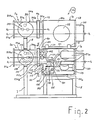
- the auxiliary unit U2, Figure 2 is formed by the juxtaposition of four sub-assemblies 1 a, 1 b, 2 a, 2 b filled with sulfur hexafluoride (SF6) and supported on a base 5 and support means 7 and 8.
- the two sub-assemblies 1 a, 1 b are identical and include two superimposed cylindrical compartments 100 a, 100 b, each containing a potential transformer PT 21, PT 22 three-phase, for measuring the voltage alternative of the sections BUS 21, BUS 22 of the double busbar, and a disconnector ESW 21, ESW 22 for earthing said sections. Only the subset 1b will be described in detail below.
- the three-phase potential transformer PT22 is secured to a bottom 113, associated with a flange 111 of the compartment 100 b, and is connected by connection conductors 120, 121, to connection points 401, 402 carried by a support insulator 4 b disc-shaped.
- the flange 111 of the cylindrical compartment 100 b Opposite the flange 111 of the cylindrical compartment 100 b, is the flange 110, to which is attached a flange 112, having an end piece 101 b eccentric flanged connection flange 115.
- the axis 0202 of the end piece 101 b is offset radially, relative to the parallel axis 01 01 of the compartment 100 b.
- the diameter of the flange 115 is less than that of the flange 110, and the support insulator 4 b is interposed between the flange 115 and the casing 200 b of the three-phase busbar section BUS 22 of the sub-assembly 2 b.
- the casing 200 b comprises a cylindrical casing 202 b, the longitudinal axis of which coincides with the axis 02 02 of the offset nozzle 101 b for connecting the compartment 100 b.
- the casing 202 b is closed opposite the insulator 4 b by a plate 211 b, and contains three conductors 210 for the electrical connection between the connection points 401, 402 of the conductors 120 and the bars 203 of the respective phases of the busbar section BUS 22.
- the eccentric position of the connecting piece 101 b allows the ESW 22 earthing switch to be arranged inside the compartment 100 b in a free space provided between the conductors 120 and the lower side wall of the compartment 100 b cylindrical.
- the ESW disconnector 22 includes a mechanism 132 carried by an insulating support 131, and intended to actuate in translation three movable pins 133, cooperating in the closed position with corresponding fixed contacts 130, secured to the conductors 120.
- the mechanism 132 is equipped with a control crank 134, rotatably mounted on an axis 135, and articulated on the isolated ends of the pins 133.
- Connection conductors 136 for the earthing of the busbar section 22 BUS connect the disconnector ESW 22 to three earthing studs 151, each stud 151 being associated with a bushing insulator 150.
- the three bushing insulators 150 are aligned and positioned transversely at regular intervals on the flange 112, below the eccentric connection piece 101 b (see figure 3).
- the three studs 151 are connected externally to earth to ensure the earthing of the busbar BUS 22, when the FSW switch 22 is switched to the closed position.
- the subassembly 1 a for housing the potential transformer TP 21 and the earthing switch ESW 21 is connected in an identical manner by the end piece 101 eccentric to the subassembly 2 a containing the game clearance section. BUS bars 21.
- the identical elements of the sub-assemblies 1 a, 2 a will have the same reference numbers as those of the sub-assemblies 1 b, 2 b, but assigned the index "a".
- the upper sub-assemblies 1 a, 2 a are superimposed on the lower sub-assemblies 1 b, 2 b with the interposition of the support means 6, 8.
- the main unit U1 in FIG. 4 comprises a central casing 10 for housing the circuit breaker CB, the earthing switches ESW 11, ESW 12 and the current transformers CT 11, CT12.
- the flange 16 of the enclosure 10 is connected by a support insulator 17 to another juxtaposed enclosure 18, enclosing the line disconnector DS 13, the earthing switch ESW 13, the arrester LA and the outlet CHd.
- the envelope 18 rests on a casing 19, in which the conductors C of departure or arrival extend.
- the casing 10 is provided with two other superimposed flanges 12 a, 12 b, connected by support insulators 13 a, 13 b to casings 14 a, 14 b cylindrical containing the corresponding sections BUS 11, BUS 12 of the double busbar.
- Each casing 14 a, 14 b is closed off by a closing plate 15 a, 15 b, and also serves as a housing for the corresponding switch disconnector DS 11, DS 12.
- the central envelope 10 is supported on a base 11 in which the CB circuit breaker control mechanism is located.
- the sections of the double busbar are connected laterally, that is to say the BUS 21 with the BUS 11, and the BUS 22 with the BUS 12.
- the bars 203 of the three-phase double busbar extend orthogonally with respect to the longitudinal arrangement of the two parallel units U1 and U2.
- auxiliary unit U2 of FIG. 5 the same references are used to designate elements identical to those of FIG. 2.
- the architecture of the unit U2 has been turned over with respect to the plane of FIG. 2 , and the sub-assemblies 1 a, 2 a, have also been rotated 180 degrees. It follows that the total height H1 of the double busbar is less than the height H2 of the sub-assembly 1 a, while it was substantially identical in the embodiment in Figure 2.
- FIG. 6 represents the main unit U1 intended to be associated with the auxiliary unit U2 of FIG. 5.
- the central tank 500 contains the circuit breaker CB, the three earthing switches ESW 11, ESW 12, ESW 13, the disconnector of DS 13 line, CT 11, CT 12 current transformers and CHd feeder.
- Each BUS 11, BUS 12 section of the three-phase busbar is housed with the corresponding switch DS 11, DS 12 in a compartment 503 a, 503 b connected to a flange 501 a, 501 b of the tank 500 by an isolator. support 502 a, 502 b.
- a third support insulator 502 C is used for the connection of an auxiliary casing 522 comprising a chamber 520 for housing the arrester LA and another chamber 521 for a potential transformer PT.
- the front part 512, 514 of the tank 500 opposite the busbar, and the upper face 506 are equipped with means 507, 508, 511 for controlling and monitoring the equipment contained inside the tank 500.
Landscapes
- Engineering & Computer Science (AREA)
- Power Engineering (AREA)
- Gas-Insulated Switchgears (AREA)
- Transformer Cooling (AREA)
Priority Applications (1)
| Application Number | Priority Date | Filing Date | Title |
|---|---|---|---|
| AT85420091T ATE36098T1 (de) | 1984-05-24 | 1985-05-15 | Metallverkapselte gasisolierte dreiphasige schaltanlage. |
Applications Claiming Priority (2)
| Application Number | Priority Date | Filing Date | Title |
|---|---|---|---|
| JP59103735A JPS60249806A (ja) | 1984-05-24 | 1984-05-24 | ガス絶縁開閉装置用母線電圧変成器ユニツト |
| JP103735/84 | 1984-05-24 |
Publications (2)
| Publication Number | Publication Date |
|---|---|
| EP0165184A1 EP0165184A1 (fr) | 1985-12-18 |
| EP0165184B1 true EP0165184B1 (fr) | 1988-07-27 |
Family
ID=14361886
Family Applications (1)
| Application Number | Title | Priority Date | Filing Date |
|---|---|---|---|
| EP85420091A Expired EP0165184B1 (fr) | 1984-05-24 | 1985-05-15 | Poste blindé triphasé à isolement gazeux |
Country Status (4)
| Country | Link |
|---|---|
| EP (1) | EP0165184B1 (ja) |
| JP (1) | JPS60249806A (ja) |
| AT (1) | ATE36098T1 (ja) |
| DE (1) | DE3564062D1 (ja) |
Cited By (7)
| Publication number | Priority date | Publication date | Assignee | Title |
|---|---|---|---|---|
| EP0244630A2 (en) * | 1986-04-01 | 1987-11-11 | Hitachi, Ltd. | Compact-type gas-insulated switchgear apparatus |
| US4996485A (en) * | 1988-12-14 | 1991-02-26 | Mitsubishi Denki Kabushiki Kaisha | Gas insulated switch device |
| EP0463490A1 (en) * | 1990-06-27 | 1992-01-02 | Hitachi, Ltd. | Gas insulated switching device |
| EP0564899A2 (de) * | 1992-03-30 | 1993-10-13 | ABBPATENT GmbH | Hochspannungsschaltfeld |
| EP0708514A2 (de) | 1994-10-19 | 1996-04-24 | Siemens Aktiengesellschaft | Metallgekapselte Hochspannungsschaltanlage mit einer dreipolig gekapselten Sammelschiene |
| DE102006040035A1 (de) * | 2006-08-23 | 2008-02-28 | Siemens Ag | Anordnung mit einem Zubehörbehälter |
| DE102007047200A1 (de) * | 2007-05-31 | 2008-12-04 | Abb Technology Ag | Hochspannungsschaltanlage |
Families Citing this family (5)
| Publication number | Priority date | Publication date | Assignee | Title |
|---|---|---|---|---|
| JPS6344610U (ja) * | 1986-09-03 | 1988-03-25 | ||
| DE19906237B4 (de) * | 1999-02-15 | 2010-08-12 | Abb Ag | Gasisolierte Schaltanlage |
| DE10203035B4 (de) * | 2002-01-26 | 2010-04-15 | Abb Ag | Gasisolierte Hochspannungsschaltanlage |
| CN103647225B (zh) * | 2013-11-22 | 2016-06-15 | 国家电网公司 | 特高压gis配电装置的布置结构 |
| CN105977857A (zh) * | 2016-06-12 | 2016-09-28 | 国网山东省电力公司青岛供电公司 | 一种110kV内桥接线GIS设备结构 |
Family Cites Families (3)
| Publication number | Priority date | Publication date | Assignee | Title |
|---|---|---|---|---|
| NL82871B (ja) * | 1936-06-12 | |||
| FR1434407A (fr) * | 1965-02-26 | 1966-04-08 | Alsthom Cgee | Nouvelles dispositions de disjoncteurs à coupure dans le vide pour les très hautes tensions |
| GB1141962A (en) * | 1966-03-18 | 1969-02-05 | Ass Elect Ind | Improved electric switchgear |
-
1984
- 1984-05-24 JP JP59103735A patent/JPS60249806A/ja active Pending
-
1985
- 1985-05-15 DE DE8585420091T patent/DE3564062D1/de not_active Expired
- 1985-05-15 EP EP85420091A patent/EP0165184B1/fr not_active Expired
- 1985-05-15 AT AT85420091T patent/ATE36098T1/de active
Cited By (9)
| Publication number | Priority date | Publication date | Assignee | Title |
|---|---|---|---|---|
| EP0244630A2 (en) * | 1986-04-01 | 1987-11-11 | Hitachi, Ltd. | Compact-type gas-insulated switchgear apparatus |
| EP0244630A3 (en) * | 1986-04-01 | 1988-12-07 | Hitachi, Ltd. | Compact-type gas-insulated switchgear apparatus |
| US4996485A (en) * | 1988-12-14 | 1991-02-26 | Mitsubishi Denki Kabushiki Kaisha | Gas insulated switch device |
| EP0463490A1 (en) * | 1990-06-27 | 1992-01-02 | Hitachi, Ltd. | Gas insulated switching device |
| EP0564899A2 (de) * | 1992-03-30 | 1993-10-13 | ABBPATENT GmbH | Hochspannungsschaltfeld |
| EP0708514A2 (de) | 1994-10-19 | 1996-04-24 | Siemens Aktiengesellschaft | Metallgekapselte Hochspannungsschaltanlage mit einer dreipolig gekapselten Sammelschiene |
| DE4438787C1 (de) * | 1994-10-19 | 1996-05-23 | Siemens Ag | Metallgekapselte Hochspannungsschaltanlage mit einer dreipolig gekapselten Sammelschiene |
| DE102006040035A1 (de) * | 2006-08-23 | 2008-02-28 | Siemens Ag | Anordnung mit einem Zubehörbehälter |
| DE102007047200A1 (de) * | 2007-05-31 | 2008-12-04 | Abb Technology Ag | Hochspannungsschaltanlage |
Also Published As
| Publication number | Publication date |
|---|---|
| ATE36098T1 (de) | 1988-08-15 |
| JPS60249806A (ja) | 1985-12-10 |
| DE3564062D1 (en) | 1988-09-01 |
| EP0165184A1 (fr) | 1985-12-18 |
Similar Documents
| Publication | Publication Date | Title |
|---|---|---|
| EP0165184B1 (fr) | Poste blindé triphasé à isolement gazeux | |
| US4241379A (en) | Gas pressurized high voltage switching installation | |
| CA2147085A1 (en) | Metal-enclosed gas-filled switchgear units | |
| FR2459565A1 (fr) | Installation de distribution a isolation gazeuse par du sf6 et a blindage metallique | |
| JP4572145B2 (ja) | ガス絶縁スイッチギヤ | |
| EP0235006B1 (fr) | Poste blindé subdivisé en compartiments étanches | |
| EP1329008B1 (fr) | Poste haute tension hybride a departs opposes en vis a vis, et modules blindes de coupure et d'aiguillage pour un tel poste | |
| EP0068951B2 (fr) | Cellule blindée à isolement gazeux pour poste électrique à moyenne tension | |
| EP0270389B1 (fr) | Interrupteur rotatif multipolaire à isolement gazeux | |
| EP0348313B1 (fr) | Poste blindé à haute tension et à double jeu de barres d'alimentation | |
| EP0871268A1 (fr) | Poste de distribution d'énergie électrique | |
| EP1226641B1 (fr) | Commutateur electrique a enveloppe metallique compartimentee pour la mise en place de sectionneurs | |
| CH650882A5 (fr) | Cellule de distribution a haute tension pour poste de transformation. | |
| EP0348312B2 (fr) | Poste blindé pour réseau à haute tension | |
| FR2558013A1 (fr) | Armoire de raccordement en derivation d'un poste electrique moyenne tension | |
| EP0338382A1 (fr) | Cellule pour poste blindé à moyenne et haute tension et poste constitué de telles cellules | |
| EP0906648A1 (fr) | Cellule electrique a caisson metallique etanche | |
| FR3002701A1 (fr) | Procede d'extraction d'une enveloppe d'un poste a isolation gazeuse sous enveloppe metallique (psem) | |
| CZ280697B6 (cs) | Zapouzdřené spínací zařízení plněné plynem | |
| FR2567688A1 (fr) | Cellule electrique triphasee a isolement gazeux | |
| EP0033691B1 (fr) | Disjoncteur à blindage tripolaire | |
| FR2629283A1 (fr) | Travee d'un poste blinde haute tension | |
| FR2550665A1 (fr) | Cellule ou tableau electrique blinde a isolement gazeux et a architecture extensible | |
| JPH0620329B2 (ja) | ガス絶縁開閉装置 | |
| EP0047214B1 (fr) | Dispositif de connexion de deux jeux de barres triphasées logés dans des enveloppes orthogonales d'une installation électrique blindée à haute tension et à isolement gazeux |
Legal Events
| Date | Code | Title | Description |
|---|---|---|---|
| PUAI | Public reference made under article 153(3) epc to a published international application that has entered the european phase |
Free format text: ORIGINAL CODE: 0009012 |
|
| AK | Designated contracting states |
Designated state(s): AT BE CH DE FR GB IT LI NL SE |
|
| 17P | Request for examination filed |
Effective date: 19860530 |
|
| ITF | It: translation for a ep patent filed |
Owner name: INTERPATENT ST.TECN. BREV. |
|
| 17Q | First examination report despatched |
Effective date: 19871013 |
|
| GRAA | (expected) grant |
Free format text: ORIGINAL CODE: 0009210 |
|
| AK | Designated contracting states |
Kind code of ref document: B1 Designated state(s): AT BE CH DE FR GB IT LI NL SE |
|
| PG25 | Lapsed in a contracting state [announced via postgrant information from national office to epo] |
Ref country code: AT Effective date: 19880727 |
|
| REF | Corresponds to: |
Ref document number: 36098 Country of ref document: AT Date of ref document: 19880815 Kind code of ref document: T |
|
| REF | Corresponds to: |
Ref document number: 3564062 Country of ref document: DE Date of ref document: 19880901 |
|
| GBT | Gb: translation of ep patent filed (gb section 77(6)(a)/1977) | ||
| PLBE | No opposition filed within time limit |
Free format text: ORIGINAL CODE: 0009261 |
|
| STAA | Information on the status of an ep patent application or granted ep patent |
Free format text: STATUS: NO OPPOSITION FILED WITHIN TIME LIMIT |
|
| 26N | No opposition filed | ||
| ITTA | It: last paid annual fee | ||
| EAL | Se: european patent in force in sweden |
Ref document number: 85420091.2 |
|
| PGFP | Annual fee paid to national office [announced via postgrant information from national office to epo] |
Ref country code: GB Payment date: 19960507 Year of fee payment: 12 |
|
| PGFP | Annual fee paid to national office [announced via postgrant information from national office to epo] |
Ref country code: CH Payment date: 19960528 Year of fee payment: 12 |
|
| PGFP | Annual fee paid to national office [announced via postgrant information from national office to epo] |
Ref country code: BE Payment date: 19960625 Year of fee payment: 12 |
|
| PG25 | Lapsed in a contracting state [announced via postgrant information from national office to epo] |
Ref country code: GB Effective date: 19970515 |
|
| PG25 | Lapsed in a contracting state [announced via postgrant information from national office to epo] |
Ref country code: LI Free format text: LAPSE BECAUSE OF NON-PAYMENT OF DUE FEES Effective date: 19970531 Ref country code: CH Free format text: LAPSE BECAUSE OF NON-PAYMENT OF DUE FEES Effective date: 19970531 Ref country code: BE Effective date: 19970531 |
|
| BERE | Be: lapsed |
Owner name: MERLIN GERIN Effective date: 19970531 |
|
| GBPC | Gb: european patent ceased through non-payment of renewal fee |
Effective date: 19970515 |
|
| REG | Reference to a national code |
Ref country code: CH Ref legal event code: PL |
|
| PGFP | Annual fee paid to national office [announced via postgrant information from national office to epo] |
Ref country code: SE Payment date: 20000504 Year of fee payment: 16 |
|
| PGFP | Annual fee paid to national office [announced via postgrant information from national office to epo] |
Ref country code: FR Payment date: 20000510 Year of fee payment: 16 |
|
| PGFP | Annual fee paid to national office [announced via postgrant information from national office to epo] |
Ref country code: DE Payment date: 20000512 Year of fee payment: 16 |
|
| PGFP | Annual fee paid to national office [announced via postgrant information from national office to epo] |
Ref country code: NL Payment date: 20000531 Year of fee payment: 16 |
|
| PG25 | Lapsed in a contracting state [announced via postgrant information from national office to epo] |
Ref country code: SE Free format text: LAPSE BECAUSE OF NON-PAYMENT OF DUE FEES Effective date: 20010516 |
|
| PG25 | Lapsed in a contracting state [announced via postgrant information from national office to epo] |
Ref country code: NL Free format text: LAPSE BECAUSE OF NON-PAYMENT OF DUE FEES Effective date: 20011201 |
|
| PG25 | Lapsed in a contracting state [announced via postgrant information from national office to epo] |
Ref country code: FR Free format text: LAPSE BECAUSE OF NON-PAYMENT OF DUE FEES Effective date: 20020131 |
|
| NLV4 | Nl: lapsed or anulled due to non-payment of the annual fee |
Effective date: 20011201 |
|
| PG25 | Lapsed in a contracting state [announced via postgrant information from national office to epo] |
Ref country code: DE Free format text: LAPSE BECAUSE OF NON-PAYMENT OF DUE FEES Effective date: 20020301 |