EP0164265A2 - Method of rolling metal slab - Google Patents
Method of rolling metal slab Download PDFInfo
- Publication number
- EP0164265A2 EP0164265A2 EP85303980A EP85303980A EP0164265A2 EP 0164265 A2 EP0164265 A2 EP 0164265A2 EP 85303980 A EP85303980 A EP 85303980A EP 85303980 A EP85303980 A EP 85303980A EP 0164265 A2 EP0164265 A2 EP 0164265A2
- Authority
- EP
- European Patent Office
- Prior art keywords
- slab
- faces
- width
- pair
- lateral edges
- Prior art date
- Legal status (The legal status is an assumption and is not a legal conclusion. Google has not performed a legal analysis and makes no representation as to the accuracy of the status listed.)
- Withdrawn
Links
- 238000000034 method Methods 0.000 title claims abstract description 15
- 239000002184 metal Substances 0.000 title claims abstract description 9
- 238000005096 rolling process Methods 0.000 title abstract description 10
- 238000005098 hot rolling Methods 0.000 claims abstract description 11
- 230000015572 biosynthetic process Effects 0.000 description 2
- 238000009749 continuous casting Methods 0.000 description 1
- 230000001788 irregular Effects 0.000 description 1
- 238000000926 separation method Methods 0.000 description 1
Images
Classifications
-
- B—PERFORMING OPERATIONS; TRANSPORTING
- B21—MECHANICAL METAL-WORKING WITHOUT ESSENTIALLY REMOVING MATERIAL; PUNCHING METAL
- B21B—ROLLING OF METAL
- B21B1/00—Metal-rolling methods or mills for making semi-finished products of solid or profiled cross-section; Sequence of operations in milling trains; Layout of rolling-mill plant, e.g. grouping of stands; Succession of passes or of sectional pass alternations
- B21B1/02—Metal-rolling methods or mills for making semi-finished products of solid or profiled cross-section; Sequence of operations in milling trains; Layout of rolling-mill plant, e.g. grouping of stands; Succession of passes or of sectional pass alternations for rolling heavy work, e.g. ingots, slabs, blooms, or billets, in which the cross-sectional form is unimportant ; Rolling combined with forging or pressing
- B21B1/026—Rolling
Definitions
- the present invention relates to a method of rolling metal slab in order to increase the width thereof.
- This stage also increases the width of the bloom and, finally, the bloom is rolled successively between pairs of cylindrical rolls in order to produce a flat of substantially uniform thickness. It will be appreciated, therefore, that, although initially a considerable reduction takes place over the central part of each of the two faces of the bloom, there is also a light reduction at the edges of the two faces.
- a method of increasing the width of a metal slab comprises the steps of hot rolling a part, but not the lateral edges, of a pair of-opposite faces of the slab to form a groove in each of the faces and to increase the width of the slab; and to hot roll the slab including the said lateral edges of said faces to reduce the slab to substantially uniform thickness.
- the lateral edges of the pair of opposite faces of the slab are not rolled while the grooves are formed in the slab and it is only subsequently that the lateral edges of the faces are rolled in order to reduce the slab to substantially uniform thickness.
- the advantage of this method is that the rolls which are required-to produce the grooves do not have a surface which engages with the full width of the slab and the depth of the grooves so formed can be varied.
- the amount of increase in slab width depends upon the depth of groove formed in the slab and this is determined by the distance set between the mill rolls.
- a method of increasing the width of a metal slab comprises the steps of hot rolling a part, but not the lateral edges, of a pair of opposite faces of the slab to form a groove in each of the faces and to increase the width of the slab; hot rolling said pair of opposite faces of the slab, but not the lateral edges thereof, to widen the groove in each of the faces and to increase the width of the slab; and hot rolling the slab, including the said.lateral edges of the faces, to reduce the slab to substantially uniform thickness.
- the rolls which are employed to widen the grooves do not have a surface which engages with the full width of the slab.
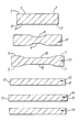
- a metal slab conveniently formed by a continuous casting operation, is of generally rectangular cross-section and has a pair of opposite faces 1, 3.
- the slab is heated to rolling temperature and is passed between a pair of rolls in a rolling mill which act on the opposite faces 1, 3 of the slab but the rolls only engage with a central portion of each face and the lateral edges 5, 7 of each face are not in engagement with the rolls.
- This causes the slab to widen and for a groove 9 to be formed in each of the pair of opposite faces.
- This slab given the reference 11, may then be hot rolled between a pair of conventional horizontal cylindrical mill rolls which reduce the thickness of the slab and, at the same time, increase its width.
- Such a slab is indicated by reference 15.
- the grooves 9 are widened by a second rolling action before the slab is passed between the cylindrical rolls.
- the slab 11 is hot rolled between a pair of rolls which are shaped to widen the grooves 9, to form grooves 10, without the rolls engaging with the lateral edges 5, 7 of the faces of the slab.
- This slab with the widened groove is indicated by reference 13.
- This slab 13 is then passed between the pair of cylindrical rolls which engage with the entire width of the pair of opposite faces to produce a slab 16.
- the mill stands having the rolls for producing the grooves 9 and the grooves 10, respectively, to be arranged in tandem with the pair of cylindrical rolls so that the initial grooves 9 are first formed, then the wider grooves 10 are formed, and then the thickness of the strip is reduced and made uniform during one pass of the slab through the mill stands.
- the sides or outside edges 17 of the slab are rather irregular and so the slab 15, 16 can be passed between a pair of vertical edger rolls which will "square-up" the edges 17 and, in doing so, will cause a slight reduction in the width of the slab.
- Reference 19 shows the slab after it has been passed through a pair of edger rolls.
- a slab may be widened considerably by the formation of one or more grooves and the subsequent rolling between a pair of cylindrical rolls with the final width of the slab being determined by the separation of the edger rolls.
- the ouside edges can be squared up by a pair of edger rolls after the grooves have been formed but before the slab is rolled between the pair of cylindrical rolls to reduce it to the required thickness.
- a conventional rougher mill may be used to produce the slab 15 of reduced thickness.
- the rolls When the grooves are produced, and subsequently widened, it is convenient for the rolls to act on not more than 70% of the width of the two faces when the grooves are initially formed and, during the second rolling step, for the rolls not to act on more than 90% of the width of the faces of the slab as the grooves are widened.
Abstract
Description
- The present invention relates to a method of rolling metal slab in order to increase the width thereof.
- It is known, from pages 99 and 100 of the book "Roll Pass Design" by B. Orr, to roll a 6 inch square bloom to a 10 inch wide flat by close-pass rolling. This is brought about by hot rolling both of a pair of opposite faces of the bloom to provide light reduction at the lateral edges of the two faces but a considerably greater reduction over the central part of each face. This brings about an increase in the width of the bloom and the formation of a groove in each face. In a second stage, the bloom is again hot rolled in order to widen the grooves in the opposite faces but, again, with a reduction at the outer edges of the two faces of the bloom. This stage also increases the width of the bloom and, finally, the bloom is rolled successively between pairs of cylindrical rolls in order to produce a flat of substantially uniform thickness. It will be appreciated, therefore, that, although initially a considerable reduction takes place over the central part of each of the two faces of the bloom, there is also a light reduction at the edges of the two faces.
- According to the present invention, a method of increasing the width of a metal slab comprises the steps of hot rolling a part, but not the lateral edges, of a pair of-opposite faces of the slab to form a groove in each of the faces and to increase the width of the slab; and to hot roll the slab including the said lateral edges of said faces to reduce the slab to substantially uniform thickness.
- It will be seen, therefore, that, initially, in accordance with the present invention, the lateral edges of the pair of opposite faces of the slab are not rolled while the grooves are formed in the slab and it is only subsequently that the lateral edges of the faces are rolled in order to reduce the slab to substantially uniform thickness.
- The advantage of this method is that the rolls which are required-to produce the grooves do not have a surface which engages with the full width of the slab and the depth of the grooves so formed can be varied. The amount of increase in slab width depends upon the depth of groove formed in the slab and this is determined by the distance set between the mill rolls. Thus, by adjusting the roll gap and, hence, the depth of the groove, the required final width of the slab can be achieved.
- In accordance with a preferred embodiment of the invention, a method of increasing the width of a metal slab comprises the steps of hot rolling a part, but not the lateral edges, of a pair of opposite faces of the slab to form a groove in each of the faces and to increase the width of the slab; hot rolling said pair of opposite faces of the slab, but not the lateral edges thereof, to widen the groove in each of the faces and to increase the width of the slab; and hot rolling the slab, including the said.lateral edges of the faces, to reduce the slab to substantially uniform thickness.
- Again, the rolls which are employed to widen the grooves do not have a surface which engages with the full width of the slab.
- In order that the invention may be more readily understood, it will now be described, by way of example only, with reference to the accompanying drawing which shows the cross-section of a metal workpiece following a succession of rolling operations.
- A metal slab, conveniently formed by a continuous casting operation, is of generally rectangular cross-section and has a pair of opposite faces 1, 3. The slab is heated to rolling temperature and is passed between a pair of rolls in a rolling mill which act on the opposite faces 1, 3 of the slab but the rolls only engage with a central portion of each face and the
lateral edges reference 11, may then be hot rolled between a pair of conventional horizontal cylindrical mill rolls which reduce the thickness of the slab and, at the same time, increase its width. Such a slab is indicated byreference 15. - In a preferred arrangement, however, the grooves 9 are widened by a second rolling action before the slab is passed between the cylindrical rolls. To this end, the
slab 11 is hot rolled between a pair of rolls which are shaped to widen the grooves 9, to formgrooves 10, without the rolls engaging with thelateral edges reference 13. Thisslab 13 is then passed between the pair of cylindrical rolls which engage with the entire width of the pair of opposite faces to produce aslab 16. It is convenient for the mill stands having the rolls for producing the grooves 9 and thegrooves 10, respectively, to be arranged in tandem with the pair of cylindrical rolls so that the initial grooves 9 are first formed, then thewider grooves 10 are formed, and then the thickness of the strip is reduced and made uniform during one pass of the slab through the mill stands. - It may be that the sides or
outside edges 17 of the slab are rather irregular and so theslab edges 17 and, in doing so, will cause a slight reduction in the width of the slab.Reference 19 shows the slab after it has been passed through a pair of edger rolls. In fact, a slab may be widened considerably by the formation of one or more grooves and the subsequent rolling between a pair of cylindrical rolls with the final width of the slab being determined by the separation of the edger rolls. As an alternative, the ouside edges can be squared up by a pair of edger rolls after the grooves have been formed but before the slab is rolled between the pair of cylindrical rolls to reduce it to the required thickness. - A conventional rougher mill may be used to produce the
slab 15 of reduced thickness. - When the grooves are produced, and subsequently widened, it is convenient for the rolls to act on not more than 70% of the width of the two faces when the grooves are initially formed and, during the second rolling step, for the rolls not to act on more than 90% of the width of the faces of the slab as the grooves are widened.
Claims (7)
Applications Claiming Priority (2)
| Application Number | Priority Date | Filing Date | Title |
|---|---|---|---|
| GB8414600 | 1984-06-08 | ||
| GB848414600A GB8414600D0 (en) | 1984-06-08 | 1984-06-08 | Rolling metal slab |
Publications (2)
| Publication Number | Publication Date |
|---|---|
| EP0164265A2 true EP0164265A2 (en) | 1985-12-11 |
| EP0164265A3 EP0164265A3 (en) | 1986-08-20 |
Family
ID=10562099
Family Applications (1)
| Application Number | Title | Priority Date | Filing Date |
|---|---|---|---|
| EP85303980A Withdrawn EP0164265A3 (en) | 1984-06-08 | 1985-06-05 | Method of rolling metal slab |
Country Status (2)
| Country | Link |
|---|---|
| EP (1) | EP0164265A3 (en) |
| GB (1) | GB8414600D0 (en) |
Cited By (4)
| Publication number | Priority date | Publication date | Assignee | Title |
|---|---|---|---|---|
| EP0234739A1 (en) * | 1986-01-29 | 1987-09-02 | DAVY McKEE (SHEFFIELD) LIMITED | The manufacture of metal strip |
| US4856313A (en) * | 1986-01-30 | 1989-08-15 | Nippon Yakin Kogyo Co., Ltd. | Method of controlling strip crown in planetary rolling |
| WO2012032301A1 (en) | 2010-09-10 | 2012-03-15 | Cambridge Enterprise Limited | Elongate beam and method for manufacturing elongate beam |
| EP2653241A1 (en) * | 2012-04-18 | 2013-10-23 | Siemens VAI Metals Technologies GmbH | Method for producing a belt |
Citations (4)
| Publication number | Priority date | Publication date | Assignee | Title |
|---|---|---|---|---|
| GB520920A (en) * | 1938-12-20 | 1940-05-07 | John Houssman | Improvements in metal rolling |
| JPS53119256A (en) * | 1977-03-28 | 1978-10-18 | Sumitomo Metal Ind Ltd | Steel plate rolling method |
| JPS55106601A (en) * | 1979-01-11 | 1980-08-15 | Nippon Kokan Kk <Nkk> | Manufacture of slab for thick steel plate by continuous casting |
| JPS58215201A (en) * | 1982-06-08 | 1983-12-14 | Kawasaki Steel Corp | Hot broadside rolling method |
-
1984
- 1984-06-08 GB GB848414600A patent/GB8414600D0/en active Pending
-
1985
- 1985-06-05 EP EP85303980A patent/EP0164265A3/en not_active Withdrawn
Patent Citations (4)
| Publication number | Priority date | Publication date | Assignee | Title |
|---|---|---|---|---|
| GB520920A (en) * | 1938-12-20 | 1940-05-07 | John Houssman | Improvements in metal rolling |
| JPS53119256A (en) * | 1977-03-28 | 1978-10-18 | Sumitomo Metal Ind Ltd | Steel plate rolling method |
| JPS55106601A (en) * | 1979-01-11 | 1980-08-15 | Nippon Kokan Kk <Nkk> | Manufacture of slab for thick steel plate by continuous casting |
| JPS58215201A (en) * | 1982-06-08 | 1983-12-14 | Kawasaki Steel Corp | Hot broadside rolling method |
Non-Patent Citations (3)
| Title |
|---|
| PATENT ABSTRACTS OF JAPAN, vol. 2, no. 152 (C-78), 20th December 1978, page 3653 C 78; & JP - A - 53 119 256 (SUMITOMO KINZOKU) 18-10-1978 * |
| PATENT ABSTRACTS OF JAPAN, vol. 4, no. 154 (M-38)[636], 28th October 1980; & JP - A - 55 106 601 (NIPPON KOKAN) 15-08-1980 * |
| PATENT ABSTRACTS OF JAPAN, vol. 8, no. 64 (M-285)[1501], 27th March 1984; & JP - A - 58 215 201 (KAWASAKI SEITETSU) 14-12-1983 * |
Cited By (5)
| Publication number | Priority date | Publication date | Assignee | Title |
|---|---|---|---|---|
| EP0234739A1 (en) * | 1986-01-29 | 1987-09-02 | DAVY McKEE (SHEFFIELD) LIMITED | The manufacture of metal strip |
| US4856313A (en) * | 1986-01-30 | 1989-08-15 | Nippon Yakin Kogyo Co., Ltd. | Method of controlling strip crown in planetary rolling |
| WO2012032301A1 (en) | 2010-09-10 | 2012-03-15 | Cambridge Enterprise Limited | Elongate beam and method for manufacturing elongate beam |
| EP2653241A1 (en) * | 2012-04-18 | 2013-10-23 | Siemens VAI Metals Technologies GmbH | Method for producing a belt |
| WO2013156332A1 (en) * | 2012-04-18 | 2013-10-24 | Siemens Vai Metals Technologies Gmbh | Method for producing a strip |
Also Published As
| Publication number | Publication date |
|---|---|
| GB8414600D0 (en) | 1984-07-11 |
| EP0164265A3 (en) | 1986-08-20 |
Similar Documents
| Publication | Publication Date | Title |
|---|---|---|
| EP0164265A2 (en) | Method of rolling metal slab | |
| ES8500100A1 (en) | Fully universal rolling process for H or I-beam type metal sections | |
| US3959863A (en) | Manufacture of agricultural discs | |
| JPH0679388A (en) | Rolling roll for special shape cross section and production of special shape cross section | |
| SU1458039A1 (en) | Vertical roll for widestrip hot rolling mill | |
| US4393679A (en) | Method for producing blank for wide flange beam | |
| GB2175229A (en) | Hot rolling slabs | |
| JP4016733B2 (en) | Rolling method for narrow flange width H-section steel | |
| GB1063373A (en) | Improvements in the process of ingot rolling | |
| JPH02112801A (en) | Universal rolling method and rolling machine for flanged shape steel | |
| JPH0675725B2 (en) | Method for manufacturing wide H-section steel | |
| SU973196A1 (en) | Method of hot rolling of wide strips | |
| SU1477484A1 (en) | Method of producing asymmetric sections | |
| US2021328A (en) | Method of rolling metal sheets | |
| SU990352A1 (en) | Method of rolling slabs on sheet mills | |
| JPS59178101A (en) | Rolling method capable of adjusting web height of h-beam | |
| JPS6087903A (en) | Installation for producing steel sheet | |
| JPS6348604B2 (en) | ||
| EP0234739B1 (en) | The manufacture of metal strip | |
| SU1424196A1 (en) | Method of hot rolling of billets from hard alloys | |
| JPS60166104A (en) | Forming method of ribbion wire by rolling | |
| JPH0761482B2 (en) | Variable flange width rolling method for rough rolled material for H-section steel | |
| JPS57146407A (en) | Rolling method for thick plate | |
| JPS6358042B2 (en) | ||
| SU899169A1 (en) | Method of multigroove rolling of billets |
Legal Events
| Date | Code | Title | Description |
|---|---|---|---|
| PUAI | Public reference made under article 153(3) epc to a published international application that has entered the european phase |
Free format text: ORIGINAL CODE: 0009012 |
|
| AK | Designated contracting states |
Designated state(s): BE DE FR GB NL |
|
| PUAL | Search report despatched |
Free format text: ORIGINAL CODE: 0009013 |
|
| AK | Designated contracting states |
Kind code of ref document: A3 Designated state(s): BE DE FR GB NL |
|
| 17P | Request for examination filed |
Effective date: 19870130 |
|
| 17Q | First examination report despatched |
Effective date: 19880429 |
|
| STAA | Information on the status of an ep patent application or granted ep patent |
Free format text: STATUS: THE APPLICATION IS DEEMED TO BE WITHDRAWN |
|
| 18D | Application deemed to be withdrawn |
Effective date: 19890413 |
|
| RIN1 | Information on inventor provided before grant (corrected) |
Inventor name: LAWSON, KENNETH THOMAS |