EP0163425A1 - Endstopfen für Brennstoffstäbe - Google Patents
Endstopfen für Brennstoffstäbe Download PDFInfo
- Publication number
- EP0163425A1 EP0163425A1 EP85303001A EP85303001A EP0163425A1 EP 0163425 A1 EP0163425 A1 EP 0163425A1 EP 85303001 A EP85303001 A EP 85303001A EP 85303001 A EP85303001 A EP 85303001A EP 0163425 A1 EP0163425 A1 EP 0163425A1
- Authority
- EP
- European Patent Office
- Prior art keywords
- plug
- end plug
- tube
- fuel rod
- cladding
- Prior art date
- Legal status (The legal status is an assumption and is not a legal conclusion. Google has not performed a legal analysis and makes no representation as to the accuracy of the status listed.)
- Ceased
Links
Images


Classifications
-
- G—PHYSICS
- G21—NUCLEAR PHYSICS; NUCLEAR ENGINEERING
- G21C—NUCLEAR REACTORS
- G21C19/00—Arrangements for treating, for handling, or for facilitating the handling of, fuel or other materials which are used within the reactor, e.g. within its pressure vessel
- G21C19/26—Arrangements for removing jammed or damaged fuel elements or control elements; Arrangements for moving broken parts thereof
-
- G—PHYSICS
- G21—NUCLEAR PHYSICS; NUCLEAR ENGINEERING
- G21C—NUCLEAR REACTORS
- G21C3/00—Reactor fuel elements and their assemblies; Selection of substances for use as reactor fuel elements
- G21C3/02—Fuel elements
- G21C3/04—Constructional details
- G21C3/06—Casings; Jackets
- G21C3/10—End closures ; Means for tight mounting therefor
-
- Y—GENERAL TAGGING OF NEW TECHNOLOGICAL DEVELOPMENTS; GENERAL TAGGING OF CROSS-SECTIONAL TECHNOLOGIES SPANNING OVER SEVERAL SECTIONS OF THE IPC; TECHNICAL SUBJECTS COVERED BY FORMER USPC CROSS-REFERENCE ART COLLECTIONS [XRACs] AND DIGESTS
- Y02—TECHNOLOGIES OR APPLICATIONS FOR MITIGATION OR ADAPTATION AGAINST CLIMATE CHANGE
- Y02E—REDUCTION OF GREENHOUSE GAS [GHG] EMISSIONS, RELATED TO ENERGY GENERATION, TRANSMISSION OR DISTRIBUTION
- Y02E30/00—Energy generation of nuclear origin
- Y02E30/30—Nuclear fission reactors
Definitions
- This invention relates to end plugs adapted to be welded within the ends of nuclear reactor fuel rods in order to close the same when fabricating the fuel rods for subsequent incorporation within the nuclear reactor core fuel assemblies.
- the end plug of the present invention facilitates the elimination of structural defects and adverse properties conventionally characteristic of the fuel rod-end plug assembly circumferential or girth weld beads, especially when the welding operations are performed in accordance with laser welding techniques, although the teachings of the present invention may also be applicable to those fuel rod-end plug assembly weld beads when the welding operations are performed in accordance with TIG welding techniques.
- the nuclear reactor core of a typical nuclear reactor facility or power plant may comprise, for example, at least one hundred or more fuel assemblies, and each fuel assembly, in turn, may comprise, for example, several hundred fuel rods.
- a conventional fuel assembly may comprise, for example, what is known as a 17 x 17 array of fuel rods wherein there are seventeen rows of fuel rod locations, and each row contains seventeen fuel rod locations. Consequently, each fuel assembly comprises two hundred sixty- four fuel rods, with the remaining locations housing control rod thimble tubes and an instrumentation tube.
- the reactor core comprised at least one hundred fuel assemblies, it can readily be seen that the core would comprise more than twenty-five thousand fuel rods.
- the nuclear reactor core fuel pins or fuel rods conventionally comprise thin-walled tubing or cladding within which the fissionable material is housed and supported in a totally encased manner during operation of the reactor.
- the cladding serves to prevent contact and chemical reactions from occurring between the nuclear fuel and the surrounding environment, such as, for example, the coolant water in a pressurized water reactor (PWR), and of course the cladding additionally serves to confine the radioactive fissionable material therewithin.
- PWR pressurized water reactor
- the cladding must therefore be corrosion-resistant, non-reactive, and heat conductive.
- Conventionally employed materials utilized in the fabrication of the fuel rod cladding include, for example, type 304 stainless steel, or zirconium based alloys, such as, for example, zircaloy-2 or zircaloy-4.
- the zirconium based alloys are in fact preferable over stainless steel materials in view of the fact that the zirconium alloys exhibit relatively low capture cross-sections with respect to thermal neutrons.
- the nuclear fuel which is usually in the form of cylindrical pellets or uranium dioxide (U0 2 ) enriched with U-235, is hermetically sealed . within the fuel rod cladding or tubing by inserting the fuel within the cladding or tubing and subsequently capping both ends of the cladding or tubing with end plugs or closures which are temporarily attached to the tubing or cladding by means of a friction or force fit.
- U0 2 uranium dioxide
- end plugs are then permanently sealed in position within the tubing or cladding by means of welding operations which are performed, for example, by means of automatic welding apparatus which rotates the fuel rod tubing relative to an electrode so as to thereby form a girth weld at the cladding-plug interfaces, the resulting assemblage of the cladding and end plugs thereby defining the completed fuel rods or pins.
- TIG welding techniques have of course been in existence for many years and have been employed in connection with welding operations within many various fields or environments. TIG welding operations are in fact highly reliable and are relatively trouble-free. Production cycle time is relatively fast, however, with the advent of laser welding technology, it has been readily realized that TIG welding operations are not nearly as fast as laser welding operations. Consequently, in order to render welding operations more cost effective and economical, it has been desired to employ laser welding techniques wherever possible in lieu of TIG welding techniques.
- the present invention resides in an end plug adapted to be welded within the end of a tube, said plug having a circumferentially extending, axially oriented land surface portion for disposing within said tube and an annularly extending, radially oriented shoulder portion for engaging the end of said tube in butt contactr fashion, characterized in that a peripheral groove is formed at the juncture of said land and shoulder portions adjacent a location for welding said plug to said tube and the groove has a depth which extends below the level of the land surface portion.
- the invention also includes a tube having an end fitted with a plug, as specified in the last preceding paragraph, which is jointed to said end by laser beam or tungsten inert gas welding.
- a groove or notch is formed within the vicinity of the aforenoted conventional internal corner structure so as to effectively replace the same.
- the groove or notch extends; around the entire periphery of the plug and is defined between the large and small diameter portions of the end' plug. While the peripheral groove or notch is partially defined by means of an annularly extending shoulder or flanged portion similar to the annular shoulder or flanged portion of the conventional end plug, the radially inwardly extending depth or extent of the annular shoulder portion of the end plug of the present invention is greater than that of the conventional fuel rod end plug. In other words, the groove has a depth which extends below the level of the land surface portion, the latter not meeting or.
- the groove is formed, in part, by means of a conical surface which extends radially outwardly and forwardly from the shoulder portion to the land surface portion, the included angle ⁇ being on the order of, for example, 45°.
- the provision of the annularly extending open notch within the weld zone in lieu of the conventional sharply defined, critically toleranced, fitted corner structure, facilitates the escape of any entrapped gas or bubbles.
- the end plugs of the present invention permit the critical machining tolerances associated with conventional TIG welding techniques to be relaxed. In the fabrication of nuclear reactor fuel rods, remarkable welding processing can be achieved, particularly in connection with the employment of laser beam welding techniques although TIG welding operations are also applicable.
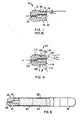
- Plug 10 normally employed for sealing the ends of fuel rod tubes or cladding wherein the assembled fuel rods will be subsequently employed within a 17 x 17 core fuel assembly.
- Plug 10 is in the form of a substantially right circular cylinder having a large diameter portion 12 and a small diameter portion 14. Small diameter portion 14 is provided with a tapered forward end 16 wherein the angle of taper ⁇ maybe; for example, 10°, the tapering of the forward end of the plug 10 serving to facilitate insertion of the plug 10 within the fuel rod cladding or tubing, not shown.
- the rearwardly extending remainder portion 18 of small diameter portion 14 of the plug 10 forms a circumferential land area which will frictionally engage the interior surface of the cladding or tubing end when the end plug 10 is inserted within the cladding or tubing, not shown. Due to the different diametrical extents of end plug portions 12 and 14, a circumferentially extending flange or shoulder portion 20 is defined therebetween, and the end plug 10 is further provided with a bore 22 which serves to introduce highpressure inert gas into the fuel rod cladding or tubing for completion of the assembled cladding-end plug fuel rod.
- An enlarged coaxial bore 24 serves to provide fluidic communication between the gas inlet orifice or bore 22 and the interior of the fuel rod, it of course being understood that subsequent to the charging of the fuel rod interior with the pressurized inert gas, bore or orifice port 22 is sealed by means of a suitable welding operation.
- porosity conditions will be observed within the weld bead, which can lead to structural. integrity and strength problems, and similarly, a condition known a ' s ID undercut, wherein there is exhibited a reduction in the thickness of the cladding or tubing portion adjacent the weld area, can likewise manifest itself so as to also lead to structural integrity and strength problems, it being particularly remembered that the enclosed fuel rods are internally pressurized wherein structural weaknesses within the fuel rod casings and welds would be especially undesirable. As a result of such adherence to high quality control standards, such structural defects have in fact been minimized in connection with the fabrication of conventional fuel rods utilizing TIG welding techniques.
- an end plug for a nuclear reactor fuel rod is generally designated by the reference character 100. It will be noted that all component parts or structural features which are similar or common to both the conventional end plug 10 of Figure 1 and end plug 100 have been designated with corresponding reference characters except that all structural components of end plug 100 have reference characters within a 100 series.
- end plug 100 the precisely fabricated corner structure of end plug 10 of Figure 1 has been replaced by a machined notch or groove 126 which extends annularly about the end plug 100.
- the notch or groove 126 is formed in part by means of the radially oriented, annularly extending shoulder portion 120 as well as by means of a conical surface 128 which extends radially outwardly from the radially innermost portion of shoulder 120 to circumferentially extending, axially oriented land surface 118, surface 128 being disposed at an angle 0 of 45° with respect to shoulder portion or surface 120 and extending toward the tapered forward end 116 of the plug 100.
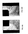
- the aforenoted production of the nuclear reactor fuel rod end plug-cladding tubing assembly was in fact produced, for example, by means of welding operations wherein a RAYTHEON 550 YAG laser was employed.
- the groove or notch 126 was machined within the sidewall of the end plug 100 to a radially inwardly depth or extent of 0.100 inches as measured from the outer surface of the land area 118, however, it later became apparent after production review of, for example, Figure 5, that a full penetration weld had in fact been adequately achieved, and that a similarly adequate heat affected zone could have been achieved with an annular groove 126 machined to a depth of, for example, only 0.05-0.07 inches. It is also to be noted.
- the groove or notch 126 of the end plug 100 of the present invention may have to be larger both in radial depth and axial extent, and in fact may have to be altered so as to comprise a different geometrical configuration, such as, for example, that of a square viewed in cross-section, as opposed to the triangularly configured groove or notch 126 which has effectively been employed in connection with laser beam welding techniques as illustrated in Figure 4.
- the present invention has significant advantages over known prior art nuclear reactor fuel rod end plugs in that by means of the provision of the notch or groove 126 within the end plugs 100 of the present invention, porosity defects or structural deficiencies within the weldment may in fact be eliminated regardless of whether TIG o:r laser beam welding technology is being employed. It is to be emphasized that while the present invention was initially developed to especially overcome defects or deficiencies manifesting themselves in connection with laser beam welding operations in connection with the fabrication of nuclear fuel rod end plug-cladding tubing assemblies, it is in fact equally applicable to TIG welding operations as noted hereinabove and for the reasons set forth hereinbefore.
- a typical nuclear reactor fuel rod 200 (which contains fuel pellets 204) includes one end plug 100 as shown in Figure 4 welded to one end of the cladding tube 202 and a second end plug 100' as shown in Figure 4 but without the bore 122 and without the bore 124 (i.e. a solid such end plug) welded to the other end of the cladding tube 202. Additionally, the bore 122 is closed by a seal weld at its outside opening 206. ⁇
Landscapes
- Physics & Mathematics (AREA)
- Engineering & Computer Science (AREA)
- Plasma & Fusion (AREA)
- General Engineering & Computer Science (AREA)
- High Energy & Nuclear Physics (AREA)
- Butt Welding And Welding Of Specific Article (AREA)
- Laser Beam Processing (AREA)
- Pipe Accessories (AREA)
- Non-Disconnectible Joints And Screw-Threaded Joints (AREA)
- Arc Welding In General (AREA)
Applications Claiming Priority (2)
| Application Number | Priority Date | Filing Date | Title |
|---|---|---|---|
| US606424 | 1984-05-02 | ||
| US06/606,424 US4865804A (en) | 1984-05-02 | 1984-05-02 | Fuel rod end plug |
Publications (1)
| Publication Number | Publication Date |
|---|---|
| EP0163425A1 true EP0163425A1 (de) | 1985-12-04 |
Family
ID=24427913
Family Applications (1)
| Application Number | Title | Priority Date | Filing Date |
|---|---|---|---|
| EP85303001A Ceased EP0163425A1 (de) | 1984-05-02 | 1985-04-29 | Endstopfen für Brennstoffstäbe |
Country Status (5)
| Country | Link |
|---|---|
| US (1) | US4865804A (de) |
| EP (1) | EP0163425A1 (de) |
| JP (1) | JPS60238783A (de) |
| KR (1) | KR850008433A (de) |
| ES (1) | ES8702050A1 (de) |
Cited By (3)
| Publication number | Priority date | Publication date | Assignee | Title |
|---|---|---|---|---|
| WO1990013898A1 (en) * | 1989-05-09 | 1990-11-15 | Abb Atom Ab | Method of sealing a fuel rod by welding |
| DE4222180A1 (de) * | 1991-07-23 | 1993-01-28 | Siemens Ag | Brennstab fuer einen kernreaktor und verfahren zum herstellen eines schweissbereichs |
| WO2003009307A1 (en) * | 2001-07-18 | 2003-01-30 | Belgonucleaire Sa | Welded mox fuel rod and method of welding a nuclear fuel rod |
Families Citing this family (18)
| Publication number | Priority date | Publication date | Assignee | Title |
|---|---|---|---|---|
| JPS62182693A (ja) * | 1986-02-06 | 1987-08-11 | 日本ニユクリア・フユエル株式会社 | 核燃料棒用端栓 |
| JP3132875B2 (ja) * | 1992-01-07 | 2001-02-05 | 三菱原子燃料株式会社 | 燃料棒の製造方法及びそれに用いる端栓 |
| ES2090440T3 (es) * | 1992-09-14 | 1996-10-16 | Siemens Ag | Barra de combustible para un reactor nuclear y dispositivo de soldadura para su fabricacion. |
| US5748691A (en) * | 1996-03-11 | 1998-05-05 | General Electric Company | Apparatus and methods for sealing end plugs for nuclear fuel rods |
| US20070160178A1 (en) * | 2006-01-11 | 2007-07-12 | Eaton Corporation | Electrical enclosure, structural assembly, and insert therefor |
| KR100956763B1 (ko) | 2008-07-04 | 2010-05-12 | 한국원자력연구원 | 이중 냉각 핵연료봉의 역원추형 하부 봉단 마개 |
| RU2480314C2 (ru) * | 2011-06-10 | 2013-04-27 | Открытое акционерное общество "Новосибирский завод химконцентратов" | Устройство для герметизации оболочек тепловыделяющих элементов контактно-стыковой сваркой с помощью заглушек |
| US9748009B2 (en) * | 2011-08-19 | 2017-08-29 | Holtec International | Container and system for handling damaged nuclear fuel, and method of making the same |
| US11515054B2 (en) | 2011-08-19 | 2022-11-29 | Holtec International | Method of retrofitting a spent nuclear fuel storage system |
| US9922731B2 (en) * | 2012-04-17 | 2018-03-20 | Bwxt Mpower, Inc. | Resistance welding of an end cap for nuclear fuel rods |
| US9418765B2 (en) * | 2013-03-14 | 2016-08-16 | Roger Ian LOUNSBURY | Nuclear reactor cores comprising a plurality of fuel elements, and fuel elements for use therein |
| RU2603355C1 (ru) * | 2015-11-26 | 2016-11-27 | Российская Федерация, от имени которой выступает Государственная корпорация по атомной энергии "Росатом" | Способ герметизации тепловыделяющих элементов ядерного реактора с оболочкой из высокохромистой стали |
| US10410754B2 (en) | 2016-10-11 | 2019-09-10 | Bwxt Mpower, Inc. | Resistance pressure weld for nuclear reactor fuel rod tube end plug |
| US11031145B2 (en) * | 2017-03-06 | 2021-06-08 | Westinghouse Electric Company Llc | Method of manufacturing a reinforced nuclear fuel cladding using an intermediate thermal deposition layer |
| CN109994221A (zh) * | 2017-12-29 | 2019-07-09 | 中核建中核燃料元件有限公司 | 一种核燃料棒上端塞 |
| CN111554422B (zh) * | 2020-04-10 | 2022-09-16 | 中核北方核燃料元件有限公司 | 一种消除焊缝气胀缺陷的端塞 |
| US20220081169A1 (en) * | 2020-09-04 | 2022-03-17 | Ut-Battelle, Llc | Press-fit special form capsule |
| CN115091117A (zh) * | 2022-05-23 | 2022-09-23 | 中冶焦耐(大连)工程技术有限公司 | 一种换热器换热管的封堵方法 |
Citations (3)
| Publication number | Priority date | Publication date | Assignee | Title |
|---|---|---|---|---|
| US3183066A (en) * | 1962-03-08 | 1965-05-11 | Westinghouse Electric Corp | Article produced by metals joining and method for producing such articles |
| FR2291578A1 (fr) * | 1974-11-15 | 1976-06-11 | Commissariat Energie Atomique | Element de combustible, pour reacteur nucleaire, et son procede de fabrication |
| FR2305827A1 (fr) * | 1975-03-24 | 1976-10-22 | Westinghouse Electric Corp | Procede pour obturer de facon etanche des cartouches de combustible de reacteur nucleaire |
Family Cites Families (6)
| Publication number | Priority date | Publication date | Assignee | Title |
|---|---|---|---|---|
| US3607638A (en) * | 1970-04-08 | 1971-09-21 | Atomic Energy Commission | Fuel element venting system |
| US4003788A (en) * | 1970-12-08 | 1977-01-18 | Westinghouse Electric Corporation | Nuclear fuel elements sealed by electric welding |
| US3836431A (en) * | 1971-05-04 | 1974-09-17 | Belgonucleaire Sa | Nuclear fuel rods having end plugs with bores therethrough sealed by frangible membranes |
| JPS50717B2 (de) * | 1971-11-30 | 1975-01-10 | ||
| US4188521A (en) * | 1977-08-15 | 1980-02-12 | Westinghouse Electric Corp. | Apparatus for welding an end plug in a nuclear fuel tube |
| JPS54141990A (en) * | 1978-04-26 | 1979-11-05 | Toshiba Corp | Method of mixed gas sealing for nuclear fuel element |
-
1984
- 1984-05-02 US US06/606,424 patent/US4865804A/en not_active Expired - Fee Related
-
1985
- 1985-04-29 EP EP85303001A patent/EP0163425A1/de not_active Ceased
- 1985-04-30 ES ES542776A patent/ES8702050A1/es not_active Expired
- 1985-05-01 KR KR1019850002960A patent/KR850008433A/ko not_active Application Discontinuation
- 1985-05-01 JP JP60092402A patent/JPS60238783A/ja active Granted
Patent Citations (3)
| Publication number | Priority date | Publication date | Assignee | Title |
|---|---|---|---|---|
| US3183066A (en) * | 1962-03-08 | 1965-05-11 | Westinghouse Electric Corp | Article produced by metals joining and method for producing such articles |
| FR2291578A1 (fr) * | 1974-11-15 | 1976-06-11 | Commissariat Energie Atomique | Element de combustible, pour reacteur nucleaire, et son procede de fabrication |
| FR2305827A1 (fr) * | 1975-03-24 | 1976-10-22 | Westinghouse Electric Corp | Procede pour obturer de facon etanche des cartouches de combustible de reacteur nucleaire |
Non-Patent Citations (1)
| Title |
|---|
| REVUE DE METALLURGIE, vol. 67, no. 2, February 1970, pages 125-131, Paris, FR; M. GRIN et al.: "Le magnésoudage" * |
Cited By (3)
| Publication number | Priority date | Publication date | Assignee | Title |
|---|---|---|---|---|
| WO1990013898A1 (en) * | 1989-05-09 | 1990-11-15 | Abb Atom Ab | Method of sealing a fuel rod by welding |
| DE4222180A1 (de) * | 1991-07-23 | 1993-01-28 | Siemens Ag | Brennstab fuer einen kernreaktor und verfahren zum herstellen eines schweissbereichs |
| WO2003009307A1 (en) * | 2001-07-18 | 2003-01-30 | Belgonucleaire Sa | Welded mox fuel rod and method of welding a nuclear fuel rod |
Also Published As
| Publication number | Publication date |
|---|---|
| ES8702050A1 (es) | 1986-12-01 |
| KR850008433A (ko) | 1985-12-16 |
| JPH0439920B2 (de) | 1992-07-01 |
| JPS60238783A (ja) | 1985-11-27 |
| US4865804A (en) | 1989-09-12 |
| ES542776A0 (es) | 1986-12-01 |
Similar Documents
| Publication | Publication Date | Title |
|---|---|---|
| US4865804A (en) | Fuel rod end plug | |
| US5158740A (en) | Fuel rod end plug welding method | |
| US3725635A (en) | Method of and apparatus for welding an end plug onto a nuclear fuel element | |
| US8811566B2 (en) | Guide thimble plug for nuclear fuel assembly | |
| US8891724B2 (en) | Dual-cooled nuclear fuel rod having annular plugs and method of manufacturing the same | |
| EP0154229B1 (de) | Brennelement für einen Kernreaktor | |
| US4699758A (en) | Reusable locking tube in a reconstitutable fuel assembly | |
| US4716018A (en) | End plug with truncated tapered leading end configuration | |
| KR910004194B1 (ko) | 원자로 핵연료 집합체의 재조립 방법 | |
| EP0048343B1 (de) | Wiederinstandsetzbares Brennelement für einen Kernreaktor | |
| US4921663A (en) | End plug weld for nuclear fuel rod | |
| US4381283A (en) | Control component structure | |
| US20030016777A1 (en) | TIG welded MOX fuel rod | |
| CN85101508A (zh) | 对燃料管管塞的改进 | |
| WO2004068503A2 (en) | Flat weld end plug | |
| US6104773A (en) | Fuel rod for a nuclear reactor | |
| US4938918A (en) | Element immersed in coolant of nuclear reactor | |
| GB2032163A (en) | Spider and Burnable Poison Rod Combinations | |
| US6697448B1 (en) | Neutronic fuel element fabrication | |
| JPS6319036B2 (de) | ||
| EP0151920B1 (de) | Verfahren zur Verarbeitung eines Steuerelementes zum Eintauchen in Kernreaktorkühlmittel | |
| US4418462A (en) | Method of assembling and disassembling a control component structure | |
| US9431134B1 (en) | Structure of top nozzle for nuclear fuel assembly | |
| Walton | Methods of assembling and disassembling spider and burnable poison rod structures for nuclear reactors | |
| US9496056B2 (en) | Combination of top nozzle and guide thimble for nuclear fuel assembly |
Legal Events
| Date | Code | Title | Description |
|---|---|---|---|
| PUAI | Public reference made under article 153(3) epc to a published international application that has entered the european phase |
Free format text: ORIGINAL CODE: 0009012 |
|
| AK | Designated contracting states |
Designated state(s): BE DE FR GB IT SE |
|
| 17P | Request for examination filed |
Effective date: 19860604 |
|
| 17Q | First examination report despatched |
Effective date: 19870911 |
|
| STAA | Information on the status of an ep patent application or granted ep patent |
Free format text: STATUS: THE APPLICATION HAS BEEN REFUSED |
|
| 18R | Application refused |
Effective date: 19891207 |
|
| RIN1 | Information on inventor provided before grant (corrected) |
Inventor name: MCGEARY, ROBERT KNOWLES Inventor name: BUCHER, GEORGE DAVID |