EP0163288A1 - Method for testing switched connexions of a multiplex space division switching network - Google Patents
Method for testing switched connexions of a multiplex space division switching network Download PDFInfo
- Publication number
- EP0163288A1 EP0163288A1 EP85106529A EP85106529A EP0163288A1 EP 0163288 A1 EP0163288 A1 EP 0163288A1 EP 85106529 A EP85106529 A EP 85106529A EP 85106529 A EP85106529 A EP 85106529A EP 0163288 A1 EP0163288 A1 EP 0163288A1
- Authority
- EP
- European Patent Office
- Prior art keywords
- switching network
- connection
- information
- output
- group
- Prior art date
- Legal status (The legal status is an assumption and is not a legal conclusion. Google has not performed a legal analysis and makes no representation as to the accuracy of the status listed.)
- Granted
Links
Images

Classifications
-
- H—ELECTRICITY
- H04—ELECTRIC COMMUNICATION TECHNIQUE
- H04Q—SELECTING
- H04Q1/00—Details of selecting apparatus or arrangements
- H04Q1/18—Electrical details
- H04Q1/20—Testing circuits or apparatus; Circuits or apparatus for detecting, indicating, or signalling faults or troubles
- H04Q1/22—Automatic arrangements
- H04Q1/24—Automatic arrangements for connection devices
- H04Q1/245—Automatic arrangements for connection devices in time-division multiplex systems
-
- H—ELECTRICITY
- H04—ELECTRIC COMMUNICATION TECHNIQUE
- H04Q—SELECTING
- H04Q11/00—Selecting arrangements for multiplex systems
- H04Q11/04—Selecting arrangements for multiplex systems for time-division multiplexing
Definitions
- the invention relates to a method for interconnection testing of a space division switching network.
- the implementation of this method involves a relatively large amount of data traffic between the central control unit of the United States averaging system and partial control units required, the individual switching network parts are individually assigned.
- an error message is issued if, in the first test run, an output signal at said one output or in the second test run a lack of an output signal at said one output and / or at the other outputs found a change in the conditions compared to the first test run unless the interim triggering of a connection is responsible for such a change.
- the test method does not require a significantly increased data flow between partial controls and central control . Since the test is carried out separately for each subunit, fault localization down to these subunits is also possible, which on the other hand must of course be purchased with circuitry effort.
- the object of the present invention is therefore to provide a method which does not have the disadvantages of the known or proposed methods described.
- test information includes the sender address designating the input used for the connection in question and the destination address characterizing the corresponding output to be used, and on the receiver side with the connection data formed by this address is compared.
- test information used according to the invention enables extensive fault localization. Since the addresses sent as test information for most types of space division switching networks are anyway in the line trunk groups, i.e. The parts of the switching matrix serving the connection of the incoming and outgoing lines are stored as connection data, the method according to the invention can be carried out with relatively little additional effort.
- the lines, to be connected by the space multiplex switching network are used in several periodically repeating periods in addition to the user information which has been switched through, the signaling, the control and the synchronization serving operating information are transmitted, the test information during the entire duration of a connection instead of the signaling information, which in turn is hidden or overwritten on the input side of the space switching network, so that the test not only detects errors when making the connection, but also errors occurring during the course of a connection can be.
- the comparison mentioned is carried out using devices assigned to the output lines, in a second version the comparison is carried out in that part of the control of the switching network which is responsible for the activation of the respective switching network output.
- the space division switching network shown in Figure 1 has 32 decentralized switching matrix parts AGO to AG31 are connected to each switching network 32 via this' to be connected to four-wire lines.
- these line trunk groups have a part AP which includes devices for buffering, clock adaptation and, if appropriate, for adding or removing stuffing pulses (stuffing, desstuffing).
- this group of connections includes a group coupler GK which, depending on whether the connected lines are subscriber lines or connecting lines, results in a traffic concentration or a traffic deconcentration.
- the group couplers have 32 connections to the connection side and 64 connections to the switching network side, thus causing the traffic to be deconcentrated towards the rest of the switching network.
- a further component of the switching network shown in FIG. 1 are central switching power supplies TKNO to TKN15, which are connected to the switching network side outputs of the connection groups AGO to AG31 via intermediate lines ZL such that each of the central switching network parts can be reached from any connection group.
- Such a space division multiplex switching network is a three-stage arrangement, namely that when a four-wire line that is connected to the AGO connection group is connected to a four-wire line that is connected to the AG31 connection group, the group switching matrix GK becomes the connection group AGO, one of the central switching network parts TKNO to TKN15 and the group switching network GK of the connection group AG31, or run through these switching network parts in the opposite direction.
- connection groups AGO is shown again in block diagram form, from which it can be seen that, in addition to the parts AP and GK already mentioned, there is a group processor GP which controls the processes taking place in the part AP and effects the setting of the group switching matrix GK.
- group processor GP which controls the processes taking place in the part AP and effects the setting of the group switching matrix GK.
- the intermediate line ZL are to be considered.
- the space division switching network in which the interconnection test according to the invention is to be carried out, is part of a telecommunications system in which not only useful information is transmitted on the four-wire lines mentioned, but also for signaling, control and synchronization Operating information, which is why the transmission on these four-wire lines takes place in periodically repeating periods of time, which are each assigned a different type of the information mentioned.
- the operating information mentioned does not need to be routed via the switching network, which is why it is hidden on the input side and, if necessary, corresponding information is added on the output side. This means that there are free periods of time on the transmission path leading over the switching network, which, as indicated, are used for the transmission of the test information provided according to the invention.
- FIG. 3 there are individual line receivers Parts of the connection unit according to FIG. 2 and in particular parts serving to carry out the method according to the invention are shown in more detail.
- FIG. 3 accordingly shows, in addition to a device for removing stuffing pulses DSt and a device for buffering and clock adaptation PT, in which a frame code word is evaluated as operating information serving for synchronization, a demultiplexer DMxs, via the outputs of the signaling and control designated ISi and ISt serving operating information is hidden and fed to the group processor, not shown, of the line group.
- Another output of the demultiplexer DMxs is connected to an input of a multiplexer Mxs, the other input of which is connected to the output of a register R and whose output is connected to one of the 32 'inputs of the group switching matrix GK.
- Figure 2 is connected to think.
- the control of the multiplexer brings about control logic AL.
- the aforementioned register R is connected via a bus interface BI to a data bus DB, via which data traffic with the group processor GP acc. Figure 2 of the connection group is possible.
- an address bus AB and a control bus CB are indicated in FIG. 3, via which the corresponding addresses and commands for connecting the group coupler are supplied by the group processor GP.
- the test information mentioned is supplied to the register R via the data bus DB mentioned.
- They consist of a sender and a destination address.
- Figure 3 which is part of the connection group AGO, the address of the relevant four-wire line connected to this connection group and the address of this connection group is stored as the sender address and the address of the connection group AG31 and the relevant four-wire line connected to it as the destination address.
- Controlled by the control logic AL is in the re g ister R checking information contained in one of the time periods have been in which transmit up to this point in the system either the frame code word or signaling or control information,tientblendet'und so that the group switching network GK of the terminal group supplied .
- circuit groups AGO to AG31 on the receiving side are provided with circuit parts which are used to carry out the test method according to the invention and are shown in detail in FIG.
- These components include a demultiplexer DMxe, the input of which is connected to a connection for transmission in the outgoing transmission direction of the group switching matrix GK of the relevant connection group. Via an output of this demultiplexer designated by IP, the test information coming from the group switching network is faded out, controlled by a control logic AL, and fed to a register R1.
- Another output of the demultiplexer Dreist is connected to the one input of a multiplexer Mxe, via the other inputs RKW, ISi and ISt of which the frame code word and possibly signaling and control information are looped in in the time periods provided for the transmission of this information.
- the output of the multiplexer Mxe leads via a possibly existing device St for adding stuffing pulses and a device IA for pulse conditioning for connection to the four-wire line branch for outgoing transmission direction.
- FIG. 4 also shows a comparator V connected to the output of register R1, the other comparator input of which is connected to a register R2.
- Register R2 is also connected via a bus interface BI to a data bus DB, via which a data exchange with the group processor of the connection group is possible.
- connection group AGO assigned to the line in question is connected receiving device according to Figure 3 during the periods in which on the connected four-wire line up to this connection group, for example, the frame code word would be transmitted, the test information consisting of the sender and destination address, located in the register R, controlled by the control logic AL, read out and via the group switching matrix GK of this connection group , one of the central switching matrix parts TKO to TKN15 and via the group switching matrix GK of the connection unit AG31. ln the receiving facility acc.
- the test information is masked out by the demultiplexer DMxe and written into the register R1.
- corresponding setting information has been written into the register R2 by the group processor of the connection group AG31. If the test information arrives at the target line group when the circuit is properly connected, the comparator V will give a positive comparison result. In the other case, the comparator sends an error message to the group processor of the connection group via the bus interface BI and the data bus DB.
- connection group identified by the sender address or one of the central switching network parts TKNO, TKN15 can be used as the fault location.
- the evaluation of the test information can also take place in the group control at the receiving end, in which case the comparator V and the register R2 are omitted.
- the query times are then also determined by the group control, which is expressed by the dashed connection between the bus interface BI and the control logic AL.
Abstract
Description
Die Erfindung betrifft ein Verfahren zur Durchschalteprüfung eines Raummultiplex-Koppelnetzes.The invention relates to a method for interconnection testing of a space division switching network.
Insbesondere bei Raummultiplex-Koppelnetzen für die . Bildkommunikation ist es wichtig, Fehler bei der Durchschaltung erkennen und möglichst eng eingrenzen zu können.Especially in space multiplex switching networks for the. It is important for image communication to be able to identify errors in the circuit and to narrow them down as closely as possible.
In diesem Zusammenhang ist es schon bekannt, jeweils nach einer Durchschaltung bei dem der betreffenden Verbindung entsprechenden Eingang des Koppelnetzes eine bestimmte Prüfbitkombination einzuspeisen und daraufhin sämtliche ausgangsseitigen Anschlüsse des Koppelnetzes auf den Empfang dieses Prüfbitmusters zu überwachen.In this context, it is already known to feed in a specific test bit combination each time a connection has been made at the input of the switching network corresponding to the connection in question, and then to monitor all of the outputs of the switching network on the receipt of this test bit pattern.
Es ist somit zwar möglich, eine Überprüfung daraufhin vorzunehmen, ob.an dem der betreffenden neugeschalteten Verbindung entsprechenden Ausgang tatsächlich ein Signal auftritt und ob dieses Signal nicht auch an einem anderen Ausgang empfangen werden kann, was eine fehlerhafte Doppelverbindung darstellen würde.It is thus possible to check whether a signal actually occurs at the output corresponding to the newly switched connection in question and whether this signal cannot also be received at another output, which would represent a faulty double connection.
Eine Lokalisierung des Durchschaltefehlers auf eine der Teileinheiten, aus denen Raumkoppelnetze üblicherweise aufgebaut sind, ist mit diesem Verfahren allerdings nicht ohneweiteres möglich. Hinzu kommt,daß die Durchführung dieses Verfahrens einen relativ großen Datenverkehr zwischen dem zentralen Steuerwerk der Vermittlungsanlage und Teilsteuerwerken erfordert, die einzelnen Koppelfeldteilen individuell zugeordnet sind.A localization of the interconnection error on one of the subunits from which space switching networks are usually constructed, however, is not possible with this method. In addition, the implementation of this method involves a relatively large amount of data traffic between the central control unit of the United States averaging system and partial control units required, the individual switching network parts are individually assigned.
Es ist auch schon vorgeschlagen worden, eine Durchschalteprüfung in der Form vorzunehmen, daß jeweils die kleinsten von einer Teilsteuerung gesondert beeinflußten Teileinheiten eines Koppelnetzes für sich im Zusammenhang mit jeder neu vorzunehmenden Durchschaltung in einem ersten Prüfdurchgang vor der Ausführung der Durchschaltung daraufhin überprüft werden, ob an dem der durchzu schaltendenverbindung entsprechenden Ausgang der Teileinheit ein Ausgangssignal und an welchen übrigen Ausgängen ein Ausgangssignal auftritt und in einem zweiten Prüfdurchgang nach der Ausführung der Durchschaltung daraufhin überprüft werden, ob an dem der durchgeschalteten Verbindung entsprechenden Ausgang nunmehr ein Ausgangssignal auftritt und ob die Verhältnisse bei allen übrigen Ausgängen unverändert geblieben sind. Eine Fehlermeldung wird bei diesem vorgeschlagenen Verfahren dann abgegeben, wenn im ersten Prüfdurchgang ein Ausgangssignal an dem genannten einen Ausgang oder im zweiten Prüfdurchgang ein Fehlen eines Ausgangssignals an dem genannten einem Ausgang und/oder an den übrigen Ausgängen eine Veränderung der Verhältnisse gegenüber dem ersten Prüfdurchgang festgestellt wird, soweit für eine solche Veränderung nicht das zwischenzeitliche Auslösen einer Verbindung verantwortlich ist. Es entfällt hier also die Einspeisung eines gesonderten Prüfsignals und die im Zuge der Durchführung der Prüfung auszuführenden Prüfschritte können durch die Teilsteuerungen veranlaßt werden, so daß hier nicht wie im vorstehend erwähnten bekannten Fall durch das Prüfverfahren ein wesentlich erhöhter Datenfluß zwischen Teilsteuerungen und Zentralsteuerung genommen werden muß. Da die Prüfung jeweils gesondert für die Teileinheiten durchgeführt wird, ist auch eine Fehlerlokalisierung bis auf diese Teileinheiten möglich, was andererseits natürlich mit schaltungsmäßigem Aufwand erkauft werden muß.It has also already been proposed to carry out a circuit test in such a way that the smallest subunits of a switching network, which are separately influenced by a partial control, are checked for themselves in connection with each new circuit to be carried out in a first test run before the circuit is carried out the output of the subunit corresponding to the connection to be switched through has an output signal and at which other outputs an output signal occurs and in a second test run after the connection has been carried out it is checked whether an output signal now occurs at the output corresponding to the switched connection and whether the conditions in all other outputs have remained unchanged. In the case of this proposed method, an error message is issued if, in the first test run, an output signal at said one output or in the second test run a lack of an output signal at said one output and / or at the other outputs found a change in the conditions compared to the first test run unless the interim triggering of a connection is responsible for such a change. There is therefore no need to feed in a separate test signal and the test steps to be carried out in the course of carrying out the test can be initiated by the partial controls, so that here, as in the known case mentioned above, the test method does not require a significantly increased data flow between partial controls and central control . Since the test is carried out separately for each subunit, fault localization down to these subunits is also possible, which on the other hand must of course be purchased with circuitry effort.
Bestimmte Fehlerkonstellationen sind mit dem genannten vorgeschlagenen Verfahren nicht erkennbar, so ist es z.B. nicht möglich, einen Fehler zu erfassen, der darin besteht, daß die Durchschaltung einer neuen Verbindung zur Entstehung einer Doppelverbindung und gleichzeitig dazu führt, daß eine ursprünglich zu dem von der Doppelverbindung betroffenen Ausgang führende,von einem anderen Eingang herkommende Verbindung aufgetrennt wird.Certain error constellations cannot be identified with the proposed method mentioned, for example it is It is not possible to detect an error which consists in the fact that the connection of a new connection leads to the formation of a double connection and at the same time that an connection originally leading to the output affected by the double connection and coming from another input is disconnected.
Die Aufgabe der vorliegenden Erfindung besteht daher darin, ein Verfahren anzugeben, das die Nachteile der geschilderten bekannten bzw, vorgeschlagenen Verfahren nicht aufweist.The object of the present invention is therefore to provide a method which does not have the disadvantages of the known or proposed methods described.
Diese Aufgabe wird bei verbindungsindividuellem eingangsseitigem Einspeisen und ausgangsseitigem Auswerten einer Prüfinformation erfindungsgemäß dadurch gelöst, daß die Prüfinformation jeweils die den für die betreffende Verbindung benutzten Eingang bezeichnende Absenderadresse sowie die den dementsprechend zu benutzenden Ausgang kennzeichnende Zieladresse umfaßt, und empfangsseitig mit den durch diese Adresse gebildeten Verbindungsdaten verglichen wird.This task is solved according to the invention in connection-specific input-side feed-in and output-side evaluation of test information in that the test information includes the sender address designating the input used for the connection in question and the destination address characterizing the corresponding output to be used, and on the receiver side with the connection data formed by this address is compared.
Die Art der erfindungsgemäß verwendeten Prüfinformationen ermöglicht eine weitgehende Fehlerlokalisierung. Da die als Prüfinformationen gesendeten Adressen bei den meisten Arten von Raummultiplex-Koppelnetzen sowieso in den Anschlußgruppen, d.h. den dem Anschluß den ankommenden und abgehenden Leitungen dienenden Teilen des Koppelfeldes als Verbindungsdaten abgespeichert sind, läßt sich das erfindungsgemäße Verfahren mit relativ geringem zusätzlichen Aufwand durchführen.The type of test information used according to the invention enables extensive fault localization. Since the addresses sent as test information for most types of space division switching networks are anyway in the line trunk groups, i.e. The parts of the switching matrix serving the connection of the incoming and outgoing lines are stored as connection data, the method according to the invention can be carried out with relatively little additional effort.
Gemäß einer Ausgestaltung der Erfindung werden im Falle eines Raummultiplex-Koppelnetzes,das Bestandteil eines Fernmeldesystems ist, bei dem auf den durch das Raummultiplex-Koppelnetz zu verbindenden' Leitungen in mehreren periodisch sich wiederholenden Zeitspannen außer der durchgeschalteten Nutzinformation der Signalisierung, der Steuerung und der Synchronisierung dienende Betriebsinformationen übertragen werden, die Prüfinformationen während der gesamten Dauer einer Verbindung anstelle der Signalisierungsinformationen übertragen, die ihrerseits eingangsseitig des Raumkoppelnetzes ausgeblendet oder überschrieben werden, so daß durch die Prüfung nicht nur Fehler bei der Vornahme der Durchschaltung sondern auch im Verlaufe einer Verbindung auftretende Fehler erkannt werden können.According to one embodiment of the invention, in the case of a space multiplex switching network which is part of a telecommunications system, the lines, to be connected by the space multiplex switching network, are used in several periodically repeating periods in addition to the user information which has been switched through, the signaling, the control and the synchronization serving operating information are transmitted, the test information during the entire duration of a connection instead of the signaling information, which in turn is hidden or overwritten on the input side of the space switching network, so that the test not only detects errors when making the connection, but also errors occurring during the course of a connection can be.
Bei einer ersten Version des erfindungsgemäßen Verfahrens wird der erwähnte Vergleich unter Verwendung den Ausgangsleitungen individuell zugeordneter Einrichtungen vorgenommen, bei einer zweiten Version erfolgt der Vergleich in demjenigen Teil der Steuerung des Koppelnetzes, der für die Aktivierung des jeweiligen Koppelfeldausgangs verantwortlich ist.In a first version of the method according to the invention, the comparison mentioned is carried out using devices assigned to the output lines, in a second version the comparison is carried out in that part of the control of the switching network which is responsible for the activation of the respective switching network output.
Nachstehend wird die Erfindung anhand von Ausführungsbeispielen unter Bezugnahme auf die Zeichnung näher erläutert.The invention is explained in more detail below on the basis of exemplary embodiments with reference to the drawing.
In der Zeichnung zeigen:
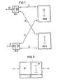
- Fig. 1 ein Beispiel für die Gliederung eines Raummultiplex-Koppelnetzes.
- Fig. 2 das Blockschaltbild einer Anschlußgruppe des Koppelfeldes gemäß Fig. 1.
- Fig. 3 die sendeseitigen leitungsindividuellen Einrichtungen der Anschlußgruppe gemäß Fig. 2 zur Durchführung des erfindungsgemäßen Verfahrens.
- Fig. 4 die empfangsseitigen leitungsindividuellen Einrichtungen der Anschlußgruppe gemäß Fig. 2 zur Durchführung des erfindungsgemäßen Verfahrens.
- Fig. 1 shows an example of the structure of a space division switching network.
- 2 shows the block diagram of a line group of the switching matrix according to FIG. 1.
- Fig. 3 shows the transmission-side line-specific devices of the connection group according to Fig. 2 for performing the method according to the invention.
- FIG. 4 shows the line-specific devices of the line group according to FIG. 2 on the receiving side for carrying out the method according to the invention.
Das in Figur 1 dargestellte Raummultiplex-Koppelfeld weist 32 dezentrale Koppelfeldteile AGO bis AG31 auf, an die jeweils 32 über dieses Koppelnetz'zu verbindende Vierdrahtleitungen angeschlossen sind.The space division switching network shown in Figure 1 has 32 decentralized switching matrix parts AGO to AG31 are connected to each
Diese Anschlußgruppen weisen einerseits einen Teil AP auf, der Einrichtungen zur Pufferung, Taktanpassung und ggf. zur Zufügung bzw. Entfernung von Stopfimpulsen (stuffing, desstuffing) umfaßt. Andererseits gehört zu diesen Anschlußgruppen ein Gruppenkoppler GK, der je nachdem ob .es sich bei den angeschlossenen Leitungen um Teilnehmerleitungen oder um Verbindungsleitungen handelt eine Verkehrskonzentrierung oder eine Verkehrsdekonzentrierung bewirkt. Im angenommenen Fall weisen die Gruppenkoppler zur Anschlußseite hin 32 Anschlüsse und zur Koppelfeldseite hin 64 Anschlüsse auf, bewirken also zum übrigen Teil des Koppelfeldes hin eine Dekonzentrierung des Verkehrs.On the one hand, these line trunk groups have a part AP which includes devices for buffering, clock adaptation and, if appropriate, for adding or removing stuffing pulses (stuffing, desstuffing). On the other hand, this group of connections includes a group coupler GK which, depending on whether the connected lines are subscriber lines or connecting lines, results in a traffic concentration or a traffic deconcentration. In the assumed case, the group couplers have 32 connections to the connection side and 64 connections to the switching network side, thus causing the traffic to be deconcentrated towards the rest of the switching network.
Weiterer Bestandteil des in Figur 1 dargegestellten Koppelnetzes sind zentrale Koppelnetzteile TKNO bis TKN15, die über Zwischenleitungen ZL derart mit den koppelfeldseitigen Ausgängen der Anschlußgruppen AGO bis AG31 verbunden sind, daß jeder der zentralen Koppelfeldteile von jeder Anschlußgruppe aus erreicht werden kann.A further component of the switching network shown in FIG. 1 are central switching power supplies TKNO to TKN15, which are connected to the switching network side outputs of the connection groups AGO to AG31 via intermediate lines ZL such that each of the central switching network parts can be reached from any connection group.
Ein derartiges Raummultiplex-Koppelnetz stellt eine dreistufige Anordnung dar, es werden nämlich beispielsweise bei einer Verbindung einer Vierdrahtleitung, die an die Anschlußgruppe AGO angeschlossen ist mit einer Vierdrahtleitung, die an die Anschlußgruppe AG31 angeschlossen ist,das Gruppenkoppelfeld GK der Anschlußgruppe AGO, eines der zentralen Koppelfeldteile TKNO bis TKN15 und das Gruppenkoppelfeld GK der Anschlußgruppe AG31, bzw. diese Koppelfeldteile in umgekehrter Richtung durchlaufen.Such a space division multiplex switching network is a three-stage arrangement, namely that when a four-wire line that is connected to the AGO connection group is connected to a four-wire line that is connected to the AG31 connection group, the group switching matrix GK becomes the connection group AGO, one of the central switching network parts TKNO to TKN15 and the group switching network GK of the connection group AG31, or run through these switching network parts in the opposite direction.
In Figur 2 ist eine der Anschlußgruppen AGO nochmals in Blockbildform dargestellt, woraus man ersieht, daß zu den schon erwähnten Teilen AP und GK noch ein Gruppenprozessor GP kommt, der die im Teil AP sich abspielenden Vorgänge steuert sowie die Einstellung des Gruppenkoppelfeldes GK bewirkt. Auf der linken Seite der Anschlußgruppe gemäß Figur 2 sind entsprechend der Darstellung in Figur 1 die Vierdrahtleitungen und auf der rechten Seite die Zwischenleitung ZL angeschlossen zu denken.In Figure 2, one of the connection groups AGO is shown again in block diagram form, from which it can be seen that, in addition to the parts AP and GK already mentioned, there is a group processor GP which controls the processes taking place in the part AP and effects the setting of the group switching matrix GK. On the left-hand side of the connection group according to FIG. 2, the four-wire lines, as shown in FIG. 1, and on the right-hand side, the intermediate line ZL are to be considered.
Bei der Erläuterung des erfindungsgemäßen Verfahrens wird vorausgesetzt, daß das Raummultiplex-Koppelnetz, bei dem die erfindungsgemäße Durchschalteprüfung durchgeführt werden soll, Bestandteil eines Fernmeldesystems ist, bei dem auf den erwähnten Vierdrahtleitungen nicht nur Nutzinformationen übertragen werden, sondern auch der Signalisierung, Steuerung und Synchronisierung dienende Betriebsinformationen, weswegen die Übertragung auf diesen Vierdrahtleitungen in periodisch sich wiederholenden Zeitspannen erfolgt, die jeweils einer anderen Art der genannten Informationen zugeordet sind. Die genannten Betriebsinformationen brauchen nicht über das Koppelnetz geführt zu werden, weswegen sie eingangsseitig ausgeblendet werden und ausgangsseitig ggf. entsprechende Informationen wieder zugefügt werden. Damit sind auf dem über das Koppelnetz führende Übertragungsweg Zeitspannen frei, die, wie angedeutet,für die Übertragung der erfindungsgemäßen vorgesehenen Prüfinformationen ausgenutzt werden.In the explanation of the method according to the invention, it is assumed that the space division switching network, in which the interconnection test according to the invention is to be carried out, is part of a telecommunications system in which not only useful information is transmitted on the four-wire lines mentioned, but also for signaling, control and synchronization Operating information, which is why the transmission on these four-wire lines takes place in periodically repeating periods of time, which are each assigned a different type of the information mentioned. The operating information mentioned does not need to be routed via the switching network, which is why it is hidden on the input side and, if necessary, corresponding information is added on the output side. This means that there are free periods of time on the transmission path leading over the switching network, which, as indicated, are used for the transmission of the test information provided according to the invention.
In der Figur 3 sind empfangsseitige leitungsindividuelle Teile der Anschlußeinheit gemäß Figur 2 und insbesondere der Durchführung des erfindungsgemäßen Verfahrens dienende Teile näher dargestellt. Die Figur 3 zeigt demnach außer einer Einrichtung zur Entfernung von Stopfimpulsen DSt und einer Einrichtung zur Pufferung und Taktanpassung PT, in der ein Rahmenkennungswort als der Synchronisierung dienende Betriebsinformation ausgewertet wird, einen Demultiplexer DMxs,über dessen mit ISi und ISt bezeichnete Ausgänge der Signalisierung und Steuerung dienende Betriebsinformationen ausgeblendet und dem nicht dargestellten Gruppenprozessor der Anschlußgruppe zugeführt werden. Ein weiterer Ausgang des Demultiplexers DMxs ist mit einem Eingang eines Multiplexers Mxs verbunden, dessen anderer Eingang mit dem Ausgang eines Registers R in Verbindung steht und dessen Ausgang an einen der 32'Eingänge des Gruppenkoppelfeldes GK gem. Figur 2 angeschlossen zu denken ist. Die Steuerung des Multiplexers bewirkt eine Ansteuerlogik AL.In FIG. 3 there are individual line receivers Parts of the connection unit according to FIG. 2 and in particular parts serving to carry out the method according to the invention are shown in more detail. FIG. 3 accordingly shows, in addition to a device for removing stuffing pulses DSt and a device for buffering and clock adaptation PT, in which a frame code word is evaluated as operating information serving for synchronization, a demultiplexer DMxs, via the outputs of the signaling and control designated ISi and ISt serving operating information is hidden and fed to the group processor, not shown, of the line group. Another output of the demultiplexer DMxs is connected to an input of a multiplexer Mxs, the other input of which is connected to the output of a register R and whose output is connected to one of the 32 'inputs of the group switching matrix GK. Figure 2 is connected to think. The control of the multiplexer brings about control logic AL.
Das erwähnte Register R steht über eine Busschnittstelle BI mit einem Datenbus DB in Verbindung,über den ein Datenverkehr mit dem Gruppenprozessor GP gem. Figur 2 der Anschlußgruppe möglich ist.The aforementioned register R is connected via a bus interface BI to a data bus DB, via which data traffic with the group processor GP acc. Figure 2 of the connection group is possible.
Fernersind in der Figur 3 ein Adreßbus AB und ein Steuerbus CB angedeutet, über die entsprechende Adressen und Befehle zur Durchschaltung des Gruppenkopplers vom Gruppenprozessor GP aus geliefert werden.In addition, an address bus AB and a control bus CB are indicated in FIG. 3, via which the corresponding addresses and commands for connecting the group coupler are supplied by the group processor GP.
Über den erwähnten Datenbus DB werden in Durchfürhung des erfindungsgemäßen Verfahrens die genannten Prüfinformationen an das Register R geliefert. Sie bestehen aus einer Absender- und einer Zieladresse. Im Falle der Verbindung einer an die Anschlußgruppe AGO angeschlossenen Vierdrahtleitung mit einer Vierdrahtleitung, die an die Anschlußgruppe AG31 angeschlossen ist und unter der Voraussetzung, daß die Verbindungsaufbaurichtung von einem Teilnehmer, der mit der an die Anschlußgruppe AGO angeschlossen Vierdrahtleitung verbunden ist, zu dem Teilnehmer führt, der an die andere genannte Vierdrahtleitung angeschlossen ist, bedeutet dies, daß im Register R gem. Figur 3, das Bestandteil der Anschlußgruppe AGO ist, als Absenderadresse die Adresse der betreffenden an diese Anschlußgruppe angeschlossenen Vierdrahtleitung und die Adresse dieser Anschlußgruppe gespeichert ist und als Zieladresse die Adresse der Anschlußgruppe AG31 und der betreffenden daran angeschlossenen Vierdrahtleitung.In carrying out the method according to the invention, the test information mentioned is supplied to the register R via the data bus DB mentioned. They consist of a sender and a destination address. In the case of connecting a four-wire line connected to the AGO connection group with a four-wire line connected to the AG31 connection group and assuming that the connection setup direction from a subscriber connected to the four-wire line connected to the AGO connection group leads to the subscriber connected to the other four-wire line mentioned, this means that in register R acc. Figure 3, which is part of the connection group AGO, the address of the relevant four-wire line connected to this connection group and the address of this connection group is stored as the sender address and the address of the connection group AG31 and the relevant four-wire line connected to it as the destination address.
Gesteuert durch die Ansteuerlogik AL wird die im Re- gister R enthaltene Prüfinformation in einer der Zeitspannen, in denen bis zu diesem Punkt des Systems entweder das Rahmenkennungswort oder Signalisierungs-oder Steuerinformation übertragen worden sind, eingeblendet'und damit dem Gruppenkoppelfeld GK der Anschlußgruppe zugeführt.Controlled by the control logic AL is in the re g ister R checking information contained in one of the time periods have been in which transmit up to this point in the system either the frame code word or signaling or control information, eingeblendet'und so that the group switching network GK of the terminal group supplied .
Ebenfalls leitungsindividuell sind bei allen Anschlußgruppen AGO bis AG31 empfangsseitige der Durchführung des erfindungsgemäßen Prüfungsverfahrens dienende Schaltungsteile vorgesehen, die im einzelnen in Figur 4 dargestellt sind.Also in line with each line, all circuit groups AGO to AG31 on the receiving side are provided with circuit parts which are used to carry out the test method according to the invention and are shown in detail in FIG.
Zu diesen Bestandteilen gehört ein Demultiplexer DMxe, dessen Eingang mit einem Anschluß für die Übertragung in abgehender Übertragungsrichtung des Gruppenkoppelfeldes GK der betreffenden Anschlußgruppe verbunden ist. Über einen mit IP bezeichneten Ausgang dieses Demultiplexers wird die vom Gruppenkoppelfeld herkommende Prüfinformation,'gesteuert durch eine Ansteuerlogik AL ausgeblendet und einem Register R1 zugeführt.These components include a demultiplexer DMxe, the input of which is connected to a connection for transmission in the outgoing transmission direction of the group switching matrix GK of the relevant connection group. Via an output of this demultiplexer designated by IP, the test information coming from the group switching network is faded out, controlled by a control logic AL, and fed to a register R1.
Ein anderer Ausgang des Demultiplexers Dreist mit dem einen Eingang eines Multiplexers Mxe verbunden, über dessen übrige Eingänge RKW, ISi und ISt das Rahmenkennungswort und ggf. Signalisierungs- und Steuerinformationen in den für die Übertragung dieser Informationen vorgesehenen Zeitspannen eingeschleift werden. Der Ausgang des Multiplexers Mxe führt über eine ggf. vorhandene Einrichtung St zur Zufügung von Stopfimpulsen und eine Einrichtung IA zur Impulsaufbereitung zum Anschluß für den Vierdrahtleitungszweig für abgehende Übertragungsrichtung.Another output of the demultiplexer Dreist is connected to the one input of a multiplexer Mxe, via the other inputs RKW, ISi and ISt of which the frame code word and possibly signaling and control information are looped in in the time periods provided for the transmission of this information. The output of the multiplexer Mxe leads via a possibly existing device St for adding stuffing pulses and a device IA for pulse conditioning for connection to the four-wire line branch for outgoing transmission direction.
Die Figur 4 zeigt ferner einen an den Ausgang des Registers R1 angeschlossenen Vergleicher V, dessen anderer Vergleichereingang mit einem Register R2 verbunden ist. Das Register R2 steht außerdem über eine Busschnittstelle BI mit einem Datenbus DB in Verbindung, über den ein Datenaustausch mit dem Gruppenprozessor der Anschlußgruppe möglich ist.FIG. 4 also shows a comparator V connected to the output of register R1, the other comparator input of which is connected to a register R2. Register R2 is also connected via a bus interface BI to a data bus DB, via which a data exchange with the group processor of the connection group is possible.
Wenn wie obenstehend angegeben eine Verbindung zwischen einer an die Anschlußgruppe AGO angeschlossenen Vierdrahtleitung mit einer an die Anschlußgruppe AG31 angeschlossenen Vierdrahtleitung durchgeschaltet wird und die Verbindungsaufbaurichtung von der Anschlußgruppe AGO zur Anschlußgruppe AG31 führt, wird in der mit der betreffenden einen Leitung zugeordneten in der Anschlußgruppe AGO befindlichen empfangsseitigen Einrichtung gem. Figur 3 während der Zeitspannen, in denen auf der angeschlossenen Vierdrahtleitung bis zu dieser Anschlußgruppe hin beispielsweise das Rahmenkennungswort übertragen würde, die entsprechend aus Absender und Zieladresse bestehende, im Register R befindliche Prüfinformation gesteuert durch die Ansteuerlogik AL, ausgelesen und über das Gruppenkoppelfeld GK dieser Anschlußgruppe, einen der zentralen Koppelfeldteile TKO bis TKN15 und über das Gruppenkoppelfeld GK der Anschlußeinheit AG31 übertragen. ln der empfangsseitigen Einrichtung gem. Fig. 4, die der anderen an der Verbindung beteiligten, an die Anschlußgruppe AG31 angeschlossenen Vierdrahtleitung zugeordnet ist, wird die Prüfinformation durch den Demultiplexer DMxe ausgeblendet und in das Register R1 eingeschrieben. Im Zugedes Verbindungsaufbaus der betrachteten Verbindung sind von dem Gruppenprozessor der Anschlußgruppe AG31 her entsprechende Einstellinformationen in das Register R2 eingeschrieben worden. Wenn also bei einer ordnungsgemäßen Durchschaltung die Prüfinformation an der Zielanschlußgruppe eintrifft, wird der Vergleicher V ein positives Vergleichsergebnis abgeben. Im anderen Fall wird durch den Vergleicher über die Busschnittstelle BI und den Datenbus DB eine Fehlermeldung an den Gruppenprozessor der Anschlußgruppe geliefert.If, as stated above, a connection between a four-wire line connected to the AGO connection group is switched through with a four-wire line connected to the AG31 connection group and the connection setup direction leads from the AGO connection group to the AG31 connection group, the connection group AGO assigned to the line in question is connected receiving device according to Figure 3 during the periods in which on the connected four-wire line up to this connection group, for example, the frame code word would be transmitted, the test information consisting of the sender and destination address, located in the register R, controlled by the control logic AL, read out and via the group switching matrix GK of this connection group , one of the central switching matrix parts TKO to TKN15 and via the group switching matrix GK of the connection unit AG31. ln the receiving facility acc. 4, which is assigned to the other four-wire line involved in the connection and connected to the connection group AG31, the test information is masked out by the demultiplexer DMxe and written into the register R1. In connection with the establishment of a connection of the connection under consideration, corresponding setting information has been written into the register R2 by the group processor of the connection group AG31. If the test information arrives at the target line group when the circuit is properly connected, the comparator V will give a positive comparison result. In the other case, the comparator sends an error message to the group processor of the connection group via the bus interface BI and the data bus DB.
Sollte es bei der betrachteten Durchschaltung zu einer Doppelverbindung gekommen sein, dann wird dies durch den Empfang der betreffenden Prüfinformation in der empfangsseitigen Einrichtung einer anderen Vierdrahtleitung, die möglicherweise sogar einer anderen Anschlußgruppe angehört, zu einer Nichtübereinstimmung von empfangener Prüfinformation mit gespeicherten Verbindungsdaten führen und damit erkannt werden. Wenn eine fehlerhafte Doppelverbindung zu einer Leitung der "richtigen" Anschlußgruppe führt, dann läßt sich aufgrund der empfangenen Zieladresse diese Anschlußgruppe als Fehlerort lokalisieren.If there is a double connection in the circuit under consideration, then the reception of the relevant test information in the receiving device of another four-wire line, which may even belong to a different line group, will result in a mismatch between the received test information and the stored connection data and thus be recognized will. If a faulty double connection leads to a line of the "correct" line group, then this line group can be localized as a fault location on the basis of the destination address received.
Führt die Doppelverbindung zu einer "falschen" Anschlußgruppe, was aus der Zieladresse erkennbar ist, dann kommt als Fehlerort die durch die Absenderadresse gekennzeichnete Anschlußgruppe oder einer der zentralen Koppelfeldteile TKNO, TKN15 infrage.If the double connection leads to a "wrong" connection group, which can be seen from the destination address, then the connection group identified by the sender address or one of the central switching network parts TKNO, TKN15 can be used as the fault location.
Unter Umständen genügt es, die vorstehend geschilderte Prüfung vor einer Nutzübertragung durchzuführen, in welchem Fall für die Übertragung der Prüfinformation die im Normalbetrieb für die Übertragung der Nutzinformation vorgesehenen Zeitspannen ausgenutzt werden können.Under certain circumstances, it is sufficient to carry out the test described above before a user transmission, in which case the time periods provided for the transmission of the user information can be used for the transmission of the test information.
Die Auswertung der Prüfinformation kann auch in der empfangsseitigen Gruppensteuerung geschehen, in welchem Fall der Vergleicher V und das Register R2 entfallen. Die Abfragezeitpunkte, werden dann ebenfalls von der Gruppensteuerung her bestimmt, was durch die gestrichelte Verbindung zwischen der Busschnittstelle BI und der Ansteuerlogik AL zum Ausdruck gebracht ist.The evaluation of the test information can also take place in the group control at the receiving end, in which case the comparator V and the register R2 are omitted. The query times are then also determined by the group control, which is expressed by the dashed connection between the bus interface BI and the control logic AL.
Claims (5)
dadurch gekennzeichnet , daß die Prüfinformationen nur während des Verbindungsaufbaus in den für die Nutzinformationen vorgesehenen Zeitspannen übertragen werden, und daß empfangsseitig einmalig ein Vergleich mit den gespeicherten Einstellinformationen vorgenommen wird.2, Veriahren according to claim 1 for use in a telecommunications system, in which on the lines to be connected by the space division switching network in periodically repeating periods other than the user information to be switched through the signaling, control and synchronization serving operating information are transmitted,
characterized in that the test information is only transmitted during the connection establishment in the time periods provided for the useful information, and in that a one-time comparison with the stored setting information is carried out at the receiving end.
dadurch gekennzeichnet , daß die Prüfinformation während der gesamten Dauer einer Verbindung anstelle einer der Betriebsinformationen, die eingangsseitig des Raummultiplex-Koppelnetzes ausgeblendet oder überschrieben und ggf. ausgangsseitig des Raummultiplex-Koppelnetzes wieder zugefügt werden, in den für diese Betriebsinformationen vorgesehenen Zeitspannen über das Raummultiplex-Koppelnetz übertragen werden, und daß empfangsseitig periodisch ein Vergleich mit den gespeicherten Einstellinformationen vorgenommen wird.3. The method as claimed in claim 1 for use in a telecommunications system in which operating information serving for signaling, control and synchronization is transmitted on the lines to be connected by the space division switching network in a plurality of periodically repeating periods of time in addition to the user information to be switched through,
characterized in that the test information for the entire duration a connection instead of one of the operating information, which is hidden or overwritten on the input side of the space multiplex switching network and possibly added again on the output side of the space multiplex switching network, is transmitted over the space multiplex switching network in the time periods provided for this operating information, and that a comparison is periodically received on the receiving side the saved setting information is made.
Applications Claiming Priority (2)
| Application Number | Priority Date | Filing Date | Title |
|---|---|---|---|
| DE3420071 | 1984-05-29 | ||
| DE3420071 | 1984-05-29 |
Publications (2)
| Publication Number | Publication Date |
|---|---|
| EP0163288A1 true EP0163288A1 (en) | 1985-12-04 |
| EP0163288B1 EP0163288B1 (en) | 1988-11-23 |
Family
ID=6237156
Family Applications (1)
| Application Number | Title | Priority Date | Filing Date |
|---|---|---|---|
| EP85106529A Expired EP0163288B1 (en) | 1984-05-29 | 1985-05-28 | Method for testing switched connexions of a multiplex space division switching network |
Country Status (2)
| Country | Link |
|---|---|
| EP (1) | EP0163288B1 (en) |
| DE (1) | DE3566482D1 (en) |
Cited By (7)
| Publication number | Priority date | Publication date | Assignee | Title |
|---|---|---|---|---|
| EP0193967A1 (en) * | 1985-03-08 | 1986-09-10 | Siemens Aktiengesellschaft | Method for connection-testing of a broad-band switching network |
| EP0198203A1 (en) * | 1985-03-08 | 1986-10-22 | Siemens Aktiengesellschaft | Method for connection-testing of a broad-band switching network |
| EP0217555A2 (en) * | 1985-09-24 | 1987-04-08 | Stc Plc | Telecommunication switching system |
| EP0248325A2 (en) * | 1986-06-02 | 1987-12-09 | Siemens Aktiengesellschaft | Method for the through-connection testing of a broadband switching network |
| EP0278289A2 (en) * | 1987-02-12 | 1988-08-17 | ANT Nachrichtentechnik GmbH | Testing device for a broadband switching network |
| EP0419019A1 (en) * | 1989-09-18 | 1991-03-27 | Gpt Limited | Message routing check system |
| EP0645922A2 (en) * | 1993-09-29 | 1995-03-29 | Siemens Aktiengesellschaft | Method for checking the switching elements of a space stage of a switching network in a TDM telecommunication exchange |
Citations (4)
| Publication number | Priority date | Publication date | Assignee | Title |
|---|---|---|---|---|
| FR2252718A1 (en) * | 1973-11-27 | 1975-06-20 | Materiel Telephonique | |
| FR2252711A1 (en) * | 1973-11-27 | 1975-06-20 | Cit Alcatel | Surveillance of multiplexed pulse code telephonic signals - is enabled by test word loop between coder and decoder |
| FR2281605A1 (en) * | 1974-08-09 | 1976-03-05 | Ericsson L M Pty Ltd | CONNECTION VERIFICATION PROCESS IN A DIGITAL DATA PROCESSING UNIT |
| FR2509944A1 (en) * | 1981-07-20 | 1983-01-21 | Int Standard Electric Corp | DIAGNOSTIC SYSTEM AND METHOD OF LOCATING DEFECTS IN A DISTRIBUTED COMMAND SWITCHING NETWORK |
-
1985
- 1985-05-28 EP EP85106529A patent/EP0163288B1/en not_active Expired
- 1985-05-28 DE DE8585106529T patent/DE3566482D1/en not_active Expired
Patent Citations (4)
| Publication number | Priority date | Publication date | Assignee | Title |
|---|---|---|---|---|
| FR2252718A1 (en) * | 1973-11-27 | 1975-06-20 | Materiel Telephonique | |
| FR2252711A1 (en) * | 1973-11-27 | 1975-06-20 | Cit Alcatel | Surveillance of multiplexed pulse code telephonic signals - is enabled by test word loop between coder and decoder |
| FR2281605A1 (en) * | 1974-08-09 | 1976-03-05 | Ericsson L M Pty Ltd | CONNECTION VERIFICATION PROCESS IN A DIGITAL DATA PROCESSING UNIT |
| FR2509944A1 (en) * | 1981-07-20 | 1983-01-21 | Int Standard Electric Corp | DIAGNOSTIC SYSTEM AND METHOD OF LOCATING DEFECTS IN A DISTRIBUTED COMMAND SWITCHING NETWORK |
Cited By (11)
| Publication number | Priority date | Publication date | Assignee | Title |
|---|---|---|---|---|
| EP0193967A1 (en) * | 1985-03-08 | 1986-09-10 | Siemens Aktiengesellschaft | Method for connection-testing of a broad-band switching network |
| EP0198203A1 (en) * | 1985-03-08 | 1986-10-22 | Siemens Aktiengesellschaft | Method for connection-testing of a broad-band switching network |
| EP0217555A2 (en) * | 1985-09-24 | 1987-04-08 | Stc Plc | Telecommunication switching system |
| EP0217555A3 (en) * | 1985-09-24 | 1989-03-01 | Stc Plc | Telecommunication switching system |
| EP0248325A2 (en) * | 1986-06-02 | 1987-12-09 | Siemens Aktiengesellschaft | Method for the through-connection testing of a broadband switching network |
| EP0248325A3 (en) * | 1986-06-02 | 1989-12-20 | Siemens Aktiengesellschaft | Method for the through-connection testing of a broadband switching network |
| EP0278289A2 (en) * | 1987-02-12 | 1988-08-17 | ANT Nachrichtentechnik GmbH | Testing device for a broadband switching network |
| EP0278289A3 (en) * | 1987-02-12 | 1990-08-01 | ANT Nachrichtentechnik GmbH | Testing device for a broadband switching network |
| EP0419019A1 (en) * | 1989-09-18 | 1991-03-27 | Gpt Limited | Message routing check system |
| EP0645922A2 (en) * | 1993-09-29 | 1995-03-29 | Siemens Aktiengesellschaft | Method for checking the switching elements of a space stage of a switching network in a TDM telecommunication exchange |
| EP0645922A3 (en) * | 1993-09-29 | 1997-06-11 | Siemens Ag | Method for checking the switching elements of a space stage of a switching network in a TDM telecommunication exchange. |
Also Published As
| Publication number | Publication date |
|---|---|
| EP0163288B1 (en) | 1988-11-23 |
| DE3566482D1 (en) | 1988-12-29 |
Similar Documents
| Publication | Publication Date | Title |
|---|---|---|
| EP0384936B1 (en) | Method and circuit arrangement for forwarding information packets from incoming links via a packet-switching device | |
| DE2848255C2 (en) | ||
| EP0448734B1 (en) | Circuit arrangement for the routine testing of the interface between transmission groups and the switching network of a PCM telecommunications exchange | |
| AT404656B (en) | LINE-REDUNDANT FIELD BUS SYSTEM, PREFERABLY WITH RING TOPOLOGY | |
| EP0163288B1 (en) | Method for testing switched connexions of a multiplex space division switching network | |
| DE3932700C2 (en) | Procedure for the interconnection test of a switching network | |
| DE2316478C3 (en) | Method for testing and maintaining the functionality of a time division multiplex switching network | |
| DE2304923C3 (en) | Procedure for testing four-wire connections between two switching points of a telecommunications network that are to be connected to one another? | |
| DE2826063A1 (en) | INDIRECTLY CONTROLLED SWITCHING SYSTEM WITH TIME CHANNEL LINKS, IN PARTICULAR TELEPHONE SWITCHING SYSTEM | |
| EP0193967B1 (en) | Method for connection-testing of a broad-band switching network | |
| DE3513165A1 (en) | Circuit arrangement for telecommunications switching systems, in particular telephone switching systems, with devices for functional capability testing of switched connections | |
| DE2849348C2 (en) | ||
| DE3513181A1 (en) | Circuit arrangement for telecommunications switching systems, in particular telephone switching systems, with devices for functional capability testing of switched connections | |
| DE2339008A1 (en) | FACILITY FOR DATA TRANSFER AND DATA BACKUP IN MULTIPLE TIME MEDIATION NETWORKS | |
| EP0272513B1 (en) | Method for testing an interface unit | |
| EP0583612B1 (en) | Method for automatically connecting a communication system to an external reference clock | |
| EP0332977A2 (en) | Method of establishing data transfer connexions in a telecommunication exchange | |
| DE2517097A1 (en) | Time multiplex signal transmission network - has branches to which individual subscriber stations are connected | |
| EP0248325B1 (en) | Method for the through-connection testing of a broadband switching network | |
| DE3821871A1 (en) | Broadband coupling device | |
| EP0198203B1 (en) | Method for connection-testing of a broad-band switching network | |
| DE2753364A1 (en) | Universal selector receiver for telephone exchanges - has processor and control for multifrequency code and dial-pulse signals | |
| DE2817598C2 (en) | Circuit arrangement for monitoring a telecommunications system, in particular a telephone exchange | |
| DE2736119C3 (en) | Circuit arrangement for telecommunications switching systems, in particular telephone switching systems with individual central devices that are common to them | |
| DE2324279C3 (en) | Method and circuit arrangement for the exchange of information in an integrated PCM telecommunications network |
Legal Events
| Date | Code | Title | Description |
|---|---|---|---|
| PUAI | Public reference made under article 153(3) epc to a published international application that has entered the european phase |
Free format text: ORIGINAL CODE: 0009012 |
|
| AK | Designated contracting states |
Designated state(s): BE CH DE FR GB IT LI NL SE |
|
| 17P | Request for examination filed |
Effective date: 19860428 |
|
| 17Q | First examination report despatched |
Effective date: 19880316 |
|
| GRAA | (expected) grant |
Free format text: ORIGINAL CODE: 0009210 |
|
| AK | Designated contracting states |
Kind code of ref document: B1 Designated state(s): BE CH DE FR GB IT LI NL SE |
|
| GBT | Gb: translation of ep patent filed (gb section 77(6)(a)/1977) | ||
| REF | Corresponds to: |
Ref document number: 3566482 Country of ref document: DE Date of ref document: 19881229 |
|
| ET | Fr: translation filed | ||
| ITF | It: translation for a ep patent filed |
Owner name: STUDIO JAUMANN |
|
| PLBE | No opposition filed within time limit |
Free format text: ORIGINAL CODE: 0009261 |
|
| STAA | Information on the status of an ep patent application or granted ep patent |
Free format text: STATUS: NO OPPOSITION FILED WITHIN TIME LIMIT |
|
| 26N | No opposition filed | ||
| ITTA | It: last paid annual fee | ||
| PGFP | Annual fee paid to national office [announced via postgrant information from national office to epo] |
Ref country code: CH Payment date: 19910823 Year of fee payment: 7 |
|
| PGFP | Annual fee paid to national office [announced via postgrant information from national office to epo] |
Ref country code: BE Payment date: 19920522 Year of fee payment: 8 |
|
| PG25 | Lapsed in a contracting state [announced via postgrant information from national office to epo] |
Ref country code: LI Effective date: 19920531 Ref country code: CH Effective date: 19920531 |
|
| REG | Reference to a national code |
Ref country code: CH Ref legal event code: PL |
|
| PG25 | Lapsed in a contracting state [announced via postgrant information from national office to epo] |
Ref country code: BE Effective date: 19930531 |
|
| BERE | Be: lapsed |
Owner name: SIEMENS A.G. BERLIN UND MUNCHEN Effective date: 19930531 |
|
| EAL | Se: european patent in force in sweden |
Ref document number: 85106529.2 |
|
| PGFP | Annual fee paid to national office [announced via postgrant information from national office to epo] |
Ref country code: GB Payment date: 19950420 Year of fee payment: 11 |
|
| PGFP | Annual fee paid to national office [announced via postgrant information from national office to epo] |
Ref country code: SE Payment date: 19950516 Year of fee payment: 11 |
|
| PGFP | Annual fee paid to national office [announced via postgrant information from national office to epo] |
Ref country code: FR Payment date: 19950522 Year of fee payment: 11 |
|
| PGFP | Annual fee paid to national office [announced via postgrant information from national office to epo] |
Ref country code: NL Payment date: 19950531 Year of fee payment: 11 |
|
| PGFP | Annual fee paid to national office [announced via postgrant information from national office to epo] |
Ref country code: DE Payment date: 19950720 Year of fee payment: 11 |
|
| PG25 | Lapsed in a contracting state [announced via postgrant information from national office to epo] |
Ref country code: GB Effective date: 19960528 |
|
| PG25 | Lapsed in a contracting state [announced via postgrant information from national office to epo] |
Ref country code: SE Effective date: 19960529 |
|
| PG25 | Lapsed in a contracting state [announced via postgrant information from national office to epo] |
Ref country code: NL Effective date: 19961201 |
|
| GBPC | Gb: european patent ceased through non-payment of renewal fee |
Effective date: 19960528 |
|
| PG25 | Lapsed in a contracting state [announced via postgrant information from national office to epo] |
Ref country code: FR Effective date: 19970131 |
|
| PG25 | Lapsed in a contracting state [announced via postgrant information from national office to epo] |
Ref country code: DE Effective date: 19970201 |
|
| EUG | Se: european patent has lapsed |
Ref document number: 85106529.2 |
|
| NLV4 | Nl: lapsed or anulled due to non-payment of the annual fee |
Effective date: 19961201 |
|
| REG | Reference to a national code |
Ref country code: FR Ref legal event code: ST |