EP0419019A1 - Message routing check system - Google Patents
Message routing check system Download PDFInfo
- Publication number
- EP0419019A1 EP0419019A1 EP90308558A EP90308558A EP0419019A1 EP 0419019 A1 EP0419019 A1 EP 0419019A1 EP 90308558 A EP90308558 A EP 90308558A EP 90308558 A EP90308558 A EP 90308558A EP 0419019 A1 EP0419019 A1 EP 0419019A1
- Authority
- EP
- European Patent Office
- Prior art keywords
- message
- message identity
- incoming
- outgoing
- identity portion
- Prior art date
- Legal status (The legal status is an assumption and is not a legal conclusion. Google has not performed a legal analysis and makes no representation as to the accuracy of the status listed.)
- Granted
Links
Images

Classifications
-
- H—ELECTRICITY
- H04—ELECTRIC COMMUNICATION TECHNIQUE
- H04Q—SELECTING
- H04Q11/00—Selecting arrangements for multiplex systems
- H04Q11/04—Selecting arrangements for multiplex systems for time-division multiplexing
-
- H—ELECTRICITY
- H04—ELECTRIC COMMUNICATION TECHNIQUE
- H04L—TRANSMISSION OF DIGITAL INFORMATION, e.g. TELEGRAPHIC COMMUNICATION
- H04L49/00—Packet switching elements
- H04L49/55—Prevention, detection or correction of errors
- H04L49/555—Error detection
-
- H—ELECTRICITY
- H04—ELECTRIC COMMUNICATION TECHNIQUE
- H04L—TRANSMISSION OF DIGITAL INFORMATION, e.g. TELEGRAPHIC COMMUNICATION
- H04L9/00—Cryptographic mechanisms or cryptographic arrangements for secret or secure communications; Network security protocols
- H04L9/40—Network security protocols
-
- H—ELECTRICITY
- H04—ELECTRIC COMMUNICATION TECHNIQUE
- H04L—TRANSMISSION OF DIGITAL INFORMATION, e.g. TELEGRAPHIC COMMUNICATION
- H04L49/00—Packet switching elements
- H04L49/30—Peripheral units, e.g. input or output ports
Abstract
Description
- The present invention concerns communication systems in which messages are sent across a switching medium. The invention is particularly applicable to sending digital data by Time Division Multiplex (TDM) and to use in the integrated Services Digital Networks (ISDN) currently being introduced. It also has applications in message switches including packet switches, ATM switches and frame relaying switches.
- In an ISDN system, as in many other systems, incoming messages to a switching medium have to be translated into outgoing messages. The present invention is concerned with systems in which this translation is carried out with reference to a mapping function, that is the incoming message is used to access an address of a stored map which gives the necessary route across the switching medium. The incoming message may include a portion which identifies its intended destination and which along with its entry point in the system be used to access the local map. It is however possible merely for the entry port at which the incoming message appears to be the determining factor in assessing the local map.
- Prior system utilizing local maps for message routing across a switching medium have all had the considerable disadvantage that fault detection is extremely difficult.
- The present invention is concerned with alleviating the above problem.
- Accordingly from one aspect the invention comprises a method of switching messages across a switching medium in which each incoming message comprises a message portion and an incoming message identity portion, the method including generating from the incoming message identity portion an outgoing message identity portion, utilising the incoming and outgoing message identity portions to route the message cross a switching medium, utilising the outgoing message identity portion to generate a further message identity portion, and comparing the incoming and further message identity portions to detect faults.
- Preferably each incoming message identity portion is associated with an incoming connection number which is also utilised in the routing of the message portion across the switching medium. In such a case the generation of the outgoing message identity portion also involves the generation of an outgoing connection number.
- From a second aspect the invention also comprises a circuit for carrying out the above identified method.
- In order that the present invention may be more readily understood, an embodiment thereof will now be described by way of example and with reference to the accompanying drawings, in which:
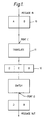
- Figure 1 is a flow diagram of a known switching system; and
- Figure 2 is a block diagram of a message switching system according to the present invention.
- Referring now to Figure 1 of the accompanying drawings this is a flow diagram illustrating the sequence of events in a known Message Switching System.
- An incoming message block is shown at 10. This message block consists of two parts, namely a message identity part A and an information part B. The message identity part is used, together with an incoming connection number C, by a
translation circuit 11 to address a local map so as to generate an outgoing message identity shown at D and an outgoing connection number E. This message block is shown at 12. The outgoing message identity and outgoing connection number are used to switch the message appropriately in a switch indicated at 13. In the particular flow diagram being described the incoming and outgoing connection numbers C and E are respectively the ports at which the message is initially received and subsequently transmitted. The final outgoing message shown at 14 thus consists of an outgoing message identity portion part D and the original information part B. - The problem with this sequence of events is that there is no way of checking that the information part has been correctly switched across the switch.
- Referring now to Figure 2 of the drawings, this shows a digital message arriving on a
line 20 for switching by aswitch 21. The message is as illustrated inblock 10 and as on Figure 1 consists of a message identity portion A and information B. In a digital switching network such as a telephone exchange messages will be arriving at a large number of ports and as explained the incoming connection or port number, in the present example, C, and the message identity portion A are used to determine the route of the message information across theswitch 21. This is done by means of atranslation circuit 22 which uses the message identity part A and the port number C to address alocal map 23. Thelocal map 23 is essentially a large memory array which when accessed by thetranslation circuit 22 maps the incoming message identity A and connection number C to generate the requisite routing information for the message to be transmitted across theswitch 21. - The output of the
translation circuit 22 after the mapping function has been carried out is shown atblock 10′ and includes the original message identity portion A, the original information B, the port number C, a new, outgoing message identifying portion D, and an outgoing port number E. This message block accordingly consists of A, C, which tells where the message has come from D, E, where the message is going, and B, the message itself. This message block is switched acrossswitch 21 to the output port correspondingto outgoing port number E. The new message block is supplied to atranslation circuit 24. Thistranslation circuit 24 acts on the outgoing message identifying portion D and outgoing port number E in a manner similar totranslation circuit 22, that is message parts D and E are used to access alocal map 25 to generate what is in effect an outgoing message identity portion and outgoing port number. However the new outgoing message identity and connection portions are merely for use in checking the routing of the switch. Thus thetranslation circuit 24 andlocal maps 25 are so arranged that they carry out the converse of the operation carried out bytranslation circuit 22 andlocal maps 23. Accordingly if the message block has been correctly switched across Switch 21 the translation of message identity D and connection number E will give the original message identity A and connection number C. - To check whether is is the case or not the output of
translation circuit 24 is supplied to acomparator 26 where A, C is compared to D, E. If there is no match this information is given to a fault detectcircuit 27, whilst if there is a match agate 28 is enabled to allow the message B and the new message identity D to pass. - By the arrangement shown in Figure 2 several different types of error can be detected. If the maps at 23 are wrong, then the cross check would fail as D, E, would not be the same as A, C.
- Similarly if the maps at 25 are wrong, then the cross check would fail as D, E, again would be different from A, C.
- If the
switch 21 miss routed or corrupted the message, then the cross check would fail as again A, C, and D, E, would be different. - Whilst the circuit described does not in itself distinguish between the type of faults, other checks may be performed to determine the exact cause of the error. For instance, the maps are likely to relate to a call, and the correct state of the connection according to the call handling be determined and compared with the local maps. If the map at 23 was wrong, then that would fail its check, if the maps at 25 were wrong then that would fail the check, if both where correct, then the most likely fault is the
switch 21 itself. There is the possibility that both were wrong, which would suggest that the path has not been correctly set-up in the first place.
Claims (3)
Applications Claiming Priority (2)
| Application Number | Priority Date | Filing Date | Title |
|---|---|---|---|
| GB898921082A GB8921082D0 (en) | 1989-09-18 | 1989-09-18 | Message routing check system |
| GB8921082 | 1989-09-18 |
Publications (2)
| Publication Number | Publication Date |
|---|---|
| EP0419019A1 true EP0419019A1 (en) | 1991-03-27 |
| EP0419019B1 EP0419019B1 (en) | 1994-11-09 |
Family
ID=10663251
Family Applications (1)
| Application Number | Title | Priority Date | Filing Date |
|---|---|---|---|
| EP90308558A Expired - Lifetime EP0419019B1 (en) | 1989-09-18 | 1990-08-03 | Message routing check system |
Country Status (13)
| Country | Link |
|---|---|
| US (1) | US5123021A (en) |
| EP (1) | EP0419019B1 (en) |
| JP (1) | JP2881185B2 (en) |
| KR (1) | KR910007308A (en) |
| CN (1) | CN1050480A (en) |
| AU (1) | AU6136990A (en) |
| CA (1) | CA2025500A1 (en) |
| DE (1) | DE69014047T2 (en) |
| ES (1) | ES2063922T3 (en) |
| FI (1) | FI904577A0 (en) |
| GB (2) | GB8921082D0 (en) |
| IE (1) | IE902847A1 (en) |
| PT (1) | PT95325A (en) |
Cited By (3)
| Publication number | Priority date | Publication date | Assignee | Title |
|---|---|---|---|---|
| US5257311A (en) * | 1991-04-30 | 1993-10-26 | Fujitsu Limited | System for monitoring ATM cross-connecting apparatus by inside-apparatus monitoring cell |
| EP0637184A2 (en) * | 1993-05-28 | 1995-02-01 | Gpt Limited | Maintenance of a TDM switching network |
| CN105743863A (en) * | 2014-12-12 | 2016-07-06 | 华为技术有限公司 | Method and device used for processing message |
Families Citing this family (1)
| Publication number | Priority date | Publication date | Assignee | Title |
|---|---|---|---|---|
| KR100441159B1 (en) * | 1999-02-01 | 2004-07-21 | 에스케이씨 주식회사 | Release film |
Citations (3)
| Publication number | Priority date | Publication date | Assignee | Title |
|---|---|---|---|---|
| FR2252718A1 (en) * | 1973-11-27 | 1975-06-20 | Materiel Telephonique | |
| US4486877A (en) * | 1982-06-25 | 1984-12-04 | At&T Bell Laboratories | Packet switching loop-around network and facilities testing |
| EP0163288A1 (en) * | 1984-05-29 | 1985-12-04 | Siemens Aktiengesellschaft | Method for testing switched connexions of a multiplex space division switching network |
Family Cites Families (5)
| Publication number | Priority date | Publication date | Assignee | Title |
|---|---|---|---|---|
| US3909562A (en) * | 1974-09-12 | 1975-09-30 | Int Standard Electric Corp | Switching network testing process and arrangement |
| US4376999A (en) * | 1980-06-03 | 1983-03-15 | Rockwell International Corporation | Muldem with monitor testing on-line and off-line paths |
| US4542507A (en) * | 1983-04-29 | 1985-09-17 | Honeywell Inc. | Apparatus for switch path verification |
| US4561090A (en) * | 1983-05-18 | 1985-12-24 | At&T Bell Laboratories | Integrated self-checking packet switch node |
| DE3801123A1 (en) * | 1988-01-16 | 1989-07-27 | Philips Patentverwaltung | MEDIATION SYSTEM |
-
1989
- 1989-09-18 GB GB898921082A patent/GB8921082D0/en active Pending
-
1990
- 1990-08-03 GB GB9017067A patent/GB2236234B/en not_active Expired - Fee Related
- 1990-08-03 DE DE69014047T patent/DE69014047T2/en not_active Expired - Fee Related
- 1990-08-03 EP EP90308558A patent/EP0419019B1/en not_active Expired - Lifetime
- 1990-08-03 ES ES90308558T patent/ES2063922T3/en not_active Expired - Lifetime
- 1990-08-07 IE IE284790A patent/IE902847A1/en unknown
- 1990-08-16 US US07/568,039 patent/US5123021A/en not_active Expired - Fee Related
- 1990-08-23 JP JP22232090A patent/JP2881185B2/en not_active Expired - Fee Related
- 1990-08-27 AU AU61369/90A patent/AU6136990A/en not_active Abandoned
- 1990-09-14 PT PT95325A patent/PT95325A/en not_active Application Discontinuation
- 1990-09-17 FI FI904577A patent/FI904577A0/en not_active IP Right Cessation
- 1990-09-17 KR KR1019900014668A patent/KR910007308A/en not_active Application Discontinuation
- 1990-09-17 CA CA002025500A patent/CA2025500A1/en not_active Abandoned
- 1990-09-18 CN CN90107905A patent/CN1050480A/en active Pending
Patent Citations (3)
| Publication number | Priority date | Publication date | Assignee | Title |
|---|---|---|---|---|
| FR2252718A1 (en) * | 1973-11-27 | 1975-06-20 | Materiel Telephonique | |
| US4486877A (en) * | 1982-06-25 | 1984-12-04 | At&T Bell Laboratories | Packet switching loop-around network and facilities testing |
| EP0163288A1 (en) * | 1984-05-29 | 1985-12-04 | Siemens Aktiengesellschaft | Method for testing switched connexions of a multiplex space division switching network |
Non-Patent Citations (3)
| Title |
|---|
| IBM TECHNICAL DISCLOSURE BULLETIN. vol. 31, no. 8, January 1989, NEW YORK US pages 414 - 427; "Method and Arrangement for Testing Switch-Network Components" * |
| IEEE JOURNAL ON SELECTED AREAS IN COMMUNICATION. vol. 6, no. 9, December 1988, NEW YORK US pages 1556 - 1564; SUZUKI et al.: "Very High-Speed and High-Capacity Packet Switching for Broadband ISDN" * |
| IEEE TRANSACTIONS ON COMMUNICATION TECHNOLOGY. vol. 36, no. 6, June 1988, NEW YORK US pages 734 - 743; J.S.TURNER: "Design of a Broadcast Packet Switching Network" * |
Cited By (6)
| Publication number | Priority date | Publication date | Assignee | Title |
|---|---|---|---|---|
| US5257311A (en) * | 1991-04-30 | 1993-10-26 | Fujitsu Limited | System for monitoring ATM cross-connecting apparatus by inside-apparatus monitoring cell |
| EP0730359A2 (en) * | 1991-04-30 | 1996-09-04 | Fujitsu Limited | System for monitoring ATM cross-connecting apparatus by inside-apparatus monitoring cell |
| EP0730359A3 (en) * | 1991-04-30 | 1998-04-01 | Fujitsu Limited | System for monitoring ATM cross-connecting apparatus by inside-apparatus monitoring cell |
| EP0637184A2 (en) * | 1993-05-28 | 1995-02-01 | Gpt Limited | Maintenance of a TDM switching network |
| EP0637184A3 (en) * | 1993-05-28 | 1996-01-10 | Plessey Telecomm | Maintenance of a TDM switching network. |
| CN105743863A (en) * | 2014-12-12 | 2016-07-06 | 华为技术有限公司 | Method and device used for processing message |
Also Published As
| Publication number | Publication date |
|---|---|
| CA2025500A1 (en) | 1991-03-19 |
| AU6136990A (en) | 1991-03-21 |
| ES2063922T3 (en) | 1995-01-16 |
| IE902847A1 (en) | 1991-03-27 |
| GB9017067D0 (en) | 1990-09-19 |
| JP2881185B2 (en) | 1999-04-12 |
| JPH03117254A (en) | 1991-05-20 |
| PT95325A (en) | 1992-05-29 |
| GB8921082D0 (en) | 1989-11-01 |
| KR910007308A (en) | 1991-04-30 |
| GB2236234B (en) | 1994-03-02 |
| CN1050480A (en) | 1991-04-03 |
| FI904577A0 (en) | 1990-09-17 |
| US5123021A (en) | 1992-06-16 |
| DE69014047D1 (en) | 1994-12-15 |
| DE69014047T2 (en) | 1995-03-23 |
| GB2236234A (en) | 1991-03-27 |
| EP0419019B1 (en) | 1994-11-09 |
Similar Documents
| Publication | Publication Date | Title |
|---|---|---|
| US6658090B1 (en) | Method and system for software updating | |
| USRE40148E1 (en) | Switched connections diagnostics in a signalling network | |
| EP0435448B1 (en) | Arrangement for routing packetized messages | |
| US4048445A (en) | Method for through connection check in digital data system | |
| US6647429B1 (en) | Method and apparatus for interconnecting token ring lans operating in ATM | |
| EP0475663A2 (en) | Communication link identifier | |
| US6424632B1 (en) | Method and apparatus for testing packet data integrity using data check field | |
| US6636484B1 (en) | Automatic generation of OAM cells for connection continuity detection | |
| JPH04248729A (en) | Atm exchange | |
| US5204858A (en) | Address setting and filtering system for terminal accommodating circuits in a packet switching system | |
| US5123021A (en) | Message routing check system | |
| US6982958B2 (en) | Method for transmitting loopback cells through a switching node of an asynchronous transfer mode (ATM) network | |
| KR100306196B1 (en) | Method and device for controlling memory | |
| JPH05191434A (en) | Atm multi-link communication system | |
| JPH1132052A (en) | Atm transmission line switching system | |
| JPH11266261A (en) | Line switching method and asynchronous mode exchange using the same | |
| JPH09181738A (en) | Local area network operated in asynchronous transfer mode to generate priority cell | |
| JPH1117686A (en) | Atm exchange system | |
| JP3132650B2 (en) | Virtual path switching device | |
| US6577629B1 (en) | Switching network with complete transfer of the contents of a header field of a cell | |
| WO1999009784A2 (en) | Cell selection for atm switch having redundant switch planes | |
| JPH01248727A (en) | Routing system exclusively used for mobile terminal equipment | |
| JPH0514391A (en) | Channel continuity test system for atm exchange | |
| JPH0311844A (en) | Switch system | |
| JPH08279848A (en) | Method for extracting fault path in communication line |
Legal Events
| Date | Code | Title | Description |
|---|---|---|---|
| PUAI | Public reference made under article 153(3) epc to a published international application that has entered the european phase |
Free format text: ORIGINAL CODE: 0009012 |
|
| AK | Designated contracting states |
Kind code of ref document: A1 Designated state(s): BE DE DK ES FR GR IT LU NL SE |
|
| 17P | Request for examination filed |
Effective date: 19910418 |
|
| RAP1 | Party data changed (applicant data changed or rights of an application transferred) |
Owner name: GPT LIMITED |
|
| 17Q | First examination report despatched |
Effective date: 19930709 |
|
| GRAA | (expected) grant |
Free format text: ORIGINAL CODE: 0009210 |
|
| AK | Designated contracting states |
Kind code of ref document: B1 Designated state(s): BE DE DK ES FR GR IT LU NL SE |
|
| PG25 | Lapsed in a contracting state [announced via postgrant information from national office to epo] |
Ref country code: NL Effective date: 19941109 Ref country code: GR Free format text: LAPSE BECAUSE OF FAILURE TO SUBMIT A TRANSLATION OF THE DESCRIPTION OR TO PAY THE FEE WITHIN THE PRESCRIBED TIME-LIMIT Effective date: 19941109 Ref country code: DK Effective date: 19941109 Ref country code: BE Effective date: 19941109 |
|
| ITF | It: translation for a ep patent filed |
Owner name: JACOBACCI CASETTA & PERANI S.P.A. |
|
| ET | Fr: translation filed | ||
| REF | Corresponds to: |
Ref document number: 69014047 Country of ref document: DE Date of ref document: 19941215 |
|
| REG | Reference to a national code |
Ref country code: ES Ref legal event code: FG2A Ref document number: 2063922 Country of ref document: ES Kind code of ref document: T3 |
|
| EAL | Se: european patent in force in sweden |
Ref document number: 90308558.7 |
|
| NLV1 | Nl: lapsed or annulled due to failure to fulfill the requirements of art. 29p and 29m of the patents act | ||
| PGFP | Annual fee paid to national office [announced via postgrant information from national office to epo] |
Ref country code: SE Payment date: 19950816 Year of fee payment: 6 |
|
| PG25 | Lapsed in a contracting state [announced via postgrant information from national office to epo] |
Ref country code: LU Free format text: LAPSE BECAUSE OF NON-PAYMENT OF DUE FEES Effective date: 19950831 |
|
| PLBE | No opposition filed within time limit |
Free format text: ORIGINAL CODE: 0009261 |
|
| STAA | Information on the status of an ep patent application or granted ep patent |
Free format text: STATUS: NO OPPOSITION FILED WITHIN TIME LIMIT |
|
| 26N | No opposition filed | ||
| PG25 | Lapsed in a contracting state [announced via postgrant information from national office to epo] |
Ref country code: SE Effective date: 19960804 |
|
| EUG | Se: european patent has lapsed |
Ref document number: 90308558.7 |
|
| PGFP | Annual fee paid to national office [announced via postgrant information from national office to epo] |
Ref country code: DE Payment date: 20020807 Year of fee payment: 13 |
|
| PGFP | Annual fee paid to national office [announced via postgrant information from national office to epo] |
Ref country code: ES Payment date: 20020826 Year of fee payment: 13 |
|
| PG25 | Lapsed in a contracting state [announced via postgrant information from national office to epo] |
Ref country code: ES Free format text: LAPSE BECAUSE OF NON-PAYMENT OF DUE FEES Effective date: 20030804 |
|
| PGFP | Annual fee paid to national office [announced via postgrant information from national office to epo] |
Ref country code: FR Payment date: 20030804 Year of fee payment: 14 |
|
| PG25 | Lapsed in a contracting state [announced via postgrant information from national office to epo] |
Ref country code: DE Free format text: LAPSE BECAUSE OF NON-PAYMENT OF DUE FEES Effective date: 20040302 |
|
| REG | Reference to a national code |
Ref country code: ES Ref legal event code: FD2A Effective date: 20030804 |
|
| PG25 | Lapsed in a contracting state [announced via postgrant information from national office to epo] |
Ref country code: FR Free format text: LAPSE BECAUSE OF NON-PAYMENT OF DUE FEES Effective date: 20050429 |
|
| REG | Reference to a national code |
Ref country code: FR Ref legal event code: ST |
|
| PG25 | Lapsed in a contracting state [announced via postgrant information from national office to epo] |
Ref country code: IT Free format text: LAPSE BECAUSE OF NON-PAYMENT OF DUE FEES;WARNING: LAPSES OF ITALIAN PATENTS WITH EFFECTIVE DATE BEFORE 2007 MAY HAVE OCCURRED AT ANY TIME BEFORE 2007. THE CORRECT EFFECTIVE DATE MAY BE DIFFERENT FROM THE ONE RECORDED. Effective date: 20050803 |