EP0163083A2 - Sich am Umfang öffnende Kernringdüsenöffnung zum Spritzgiessen - Google Patents
Sich am Umfang öffnende Kernringdüsenöffnung zum Spritzgiessen Download PDFInfo
- Publication number
- EP0163083A2 EP0163083A2 EP85104440A EP85104440A EP0163083A2 EP 0163083 A2 EP0163083 A2 EP 0163083A2 EP 85104440 A EP85104440 A EP 85104440A EP 85104440 A EP85104440 A EP 85104440A EP 0163083 A2 EP0163083 A2 EP 0163083A2
- Authority
- EP
- European Patent Office
- Prior art keywords
- valve pin
- gate
- cavity
- tip portion
- mold platen
- Prior art date
- Legal status (The legal status is an assumption and is not a legal conclusion. Google has not performed a legal analysis and makes no representation as to the accuracy of the status listed.)
- Granted
Links
- 238000001746 injection moulding Methods 0.000 title claims abstract description 11
- 230000002093 peripheral effect Effects 0.000 title 1
- 239000000155 melt Substances 0.000 claims description 14
- 238000000465 moulding Methods 0.000 claims description 6
- 241000937413 Axia Species 0.000 claims 1
- 229910000831 Steel Inorganic materials 0.000 claims 1
- 239000010959 steel Substances 0.000 claims 1
- 238000001816 cooling Methods 0.000 abstract description 8
- 230000007423 decrease Effects 0.000 abstract 1
- 229910000881 Cu alloy Inorganic materials 0.000 description 3
- 238000002347 injection Methods 0.000 description 3
- 239000007924 injection Substances 0.000 description 3
- 239000010935 stainless steel Substances 0.000 description 3
- 229910001220 stainless steel Inorganic materials 0.000 description 3
- 239000012530 fluid Substances 0.000 description 2
- 238000010438 heat treatment Methods 0.000 description 2
- RYGMFSIKBFXOCR-UHFFFAOYSA-N Copper Chemical compound [Cu] RYGMFSIKBFXOCR-UHFFFAOYSA-N 0.000 description 1
- 229910001069 Ti alloy Inorganic materials 0.000 description 1
- 239000004020 conductor Substances 0.000 description 1
- 239000010949 copper Substances 0.000 description 1
- 229910052802 copper Inorganic materials 0.000 description 1
- 238000005260 corrosion Methods 0.000 description 1
- 230000007797 corrosion Effects 0.000 description 1
- 238000005485 electric heating Methods 0.000 description 1
- 239000007789 gas Substances 0.000 description 1
- 208000015181 infectious disease Diseases 0.000 description 1
- 238000009413 insulation Methods 0.000 description 1
- 239000000463 material Substances 0.000 description 1
- 238000000034 method Methods 0.000 description 1
- 238000012986 modification Methods 0.000 description 1
- 230000004048 modification Effects 0.000 description 1
- XLYOFNOQVPJJNP-UHFFFAOYSA-N water Substances O XLYOFNOQVPJJNP-UHFFFAOYSA-N 0.000 description 1
Images

Classifications
-
- B—PERFORMING OPERATIONS; TRANSPORTING
- B29—WORKING OF PLASTICS; WORKING OF SUBSTANCES IN A PLASTIC STATE IN GENERAL
- B29C—SHAPING OR JOINING OF PLASTICS; SHAPING OF MATERIAL IN A PLASTIC STATE, NOT OTHERWISE PROVIDED FOR; AFTER-TREATMENT OF THE SHAPED PRODUCTS, e.g. REPAIRING
- B29C45/00—Injection moulding, i.e. forcing the required volume of moulding material through a nozzle into a closed mould; Apparatus therefor
- B29C45/17—Component parts, details or accessories; Auxiliary operations
- B29C45/26—Moulds
- B29C45/27—Sprue channels ; Runner channels or runner nozzles
- B29C45/28—Closure devices therefor
- B29C45/2896—Closure devices therefor extending in or through the mould cavity, e.g. valves mounted opposite the sprue channel
-
- B—PERFORMING OPERATIONS; TRANSPORTING
- B29—WORKING OF PLASTICS; WORKING OF SUBSTANCES IN A PLASTIC STATE IN GENERAL
- B29L—INDEXING SCHEME ASSOCIATED WITH SUBCLASS B29C, RELATING TO PARTICULAR ARTICLES
- B29L2015/00—Gear wheels or similar articles with grooves or projections, e.g. control knobs
- B29L2015/003—Gears
-
- Y—GENERAL TAGGING OF NEW TECHNOLOGICAL DEVELOPMENTS; GENERAL TAGGING OF CROSS-SECTIONAL TECHNOLOGIES SPANNING OVER SEVERAL SECTIONS OF THE IPC; TECHNICAL SUBJECTS COVERED BY FORMER USPC CROSS-REFERENCE ART COLLECTIONS [XRACs] AND DIGESTS
- Y10—TECHNICAL SUBJECTS COVERED BY FORMER USPC
- Y10S—TECHNICAL SUBJECTS COVERED BY FORMER USPC CROSS-REFERENCE ART COLLECTIONS [XRACs] AND DIGESTS
- Y10S425/00—Plastic article or earthenware shaping or treating: apparatus
- Y10S425/224—Injection mold nozzle valve
Definitions
- This invention relates to valve gated injection molding, and more particularly to an improved. system for molding a product such as a plastic gear or wheel with a hole through it.
- valve pin has a head portion extending from a reduced neck portion which allows the melt to flow into the. cavity around the valve pin.
- This necessarily has the disadvantage that it requires the valve pin to be operated in the reverse direction to a normal valve gated system. In other words, in these previous core ring gated systems, the valve pin must be actuated between a retracted closed position and a forward open position rather than the reverse with normal valve gated systems.
- the invention provides an injection molding system for filling a cavity which is defined between a cavity plate and a movable mold platen to form a molded product with a hole therethrough, having a gate extending .. through the cavity plate to the cavity, a bore in the movable mold platen which is in alignment with the gate, an elongated valve pin and valve pin actuating mechanism which reciprocates the valve pin between a retracted open position and a forward closed position, and a melt passage which extends through a manifold and around the valve pin to convey pressurized melt from a molding machine to the gate, with the improvement wherein the valve pin has a stem portion and a smaller diameter tip portion which extends in central alignment from a tapered shoulder at the stem portion through the gate and into the bore in the movable mold platen, the tip portion being nearly equal in diameter to the bore in the movable mold platen but substantially smaller in diameter than the gate, whereby in the retracted open position melt flows into the cavity through the
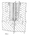
- FIG. 1 shows one cavity 10 of a multi-cavity core ring gated injection molding system.
- the cavity is formed between a cavity plate l2 and a movable mold platen 14 which abut along a parting line 16.
- Each cavity 10 has a heated nozzle 18 seated in the cavity plate 12 with a central bore 20 extending therethrough.
- a manifold 22 extends between the heated nozzle 18 and a back plate 24 and is accurately positioned relatively to the cavity plate 12 by a locating ring 26.
- a melt passage 28 branches out through the manifold 22 from a recessed inlet 30 which receives pressurized melt from a molding machine (not shown) and extends through the heated nozzle 18 to a gate 32 leading to the cavity 10.
- An elongated valve pin 34 extends through the central bore 20 of the heated nozzle 18 in alignment with the gate 32 and is reciprocated by a hydraulic actuating mechanism seated in the back plate 24.
- the valve pin has an enlarged driven end 36, a stem portion 38 and a smaller diameter tip portion 40.
- the tip portion 40 extends in axial alignment from a tapered shoulder 42 at the stem portion 38 through the gate 32 and the cavity 10, and is received in a bore 44 in the movable mold platen 14.
- the elongated tip portion 40 of the valve pin 34 has a uniform diameter to just fit into the bore 44 in the movable mold platen 14 and prevent leakage of the melt between them.
- the diameter of the gate 32 is sufficiently larger than that of the tip portion 40 to allow the cavity to fill around the tip portion when the valve pin is in the retracted open position shown in Figure 1.
- the melt passage 28 joins the central bore 20 of the heated nozzle 18 in a stainless steel bushing 46 which is seated in the heated nozzle-18 as described in Gellert's U.S. Patent No. 4,026,518 entitled "Bushing Seal for Valve-Gated Injection Mold" which issued May 31, 1977.
- the bushing seal 46 has a collar portion 48 extending up around the stem portion 38 of the valve pin to prevent leakage as described in Gellert's U.S. Patent No.
- the nozzle 18 has a corrosion resistant inner portion 52 formed of stainless steel surrounded by a highly conductive outer portion 54 formed of a copper alloy.
- the nozzle 18 is heated by an electric heating element 56 which is cast into the copper alloy portion and receives electric power from connections (not shown) to terminals 58.
- the copper alloy rapidly conducts the heat away from the heating element 56 and applies a uniform temperature to the stainless steel portion 52 to maintain the melt at a constant predetermined temperature as it flows through the central bore 20 around the valve pin 34.
- the temperature of the melt during the molding cycle is critical to the successful operation of the system.
- the cavity plate 12, movable mold platen 14 and back plate are cooled by water flowing through cooling elements 60 (or other suitable cooling means).
- the heated nozzle 18 is seated in the cavity plate 12 on an insulation bushing 62 which provides an insulative air space 64 between them. Similarly, insulative air spaces are provided between the hot manifold 22 and the cooled cavity plate 12 and back plate 24.
- the air space 64 between the nozzle 18 and the cavity plate 12 is bridged by a hollow nozzle seal 66 formed of a titanium alloy which extends around the gate 32 to prevent the pressurized melt escaping into the air space 64 as described in Gellert's U.S. Patent No. 4,043,740 entitled "Injection Molding Nozzle Seal" which issued August 23, 1977.
- the valve pin actuating mechanism seated in the back plate 24 includes a hydraulically driven piston 68 which reciprocates in a cylinder 70.
- the cylinder 70 has a collar portion 72 through which bolts 74 extend to secure it in position in the back plate 24 in alignment with the valve pin 34.
- the cylinder 70 has a removable cap 76 which is larger in diameter than the piston 68 that can be screwed out to remove the piston and valve pin if required.
- the valve pin 34 extends through a central hole 78 in the piston 68 and a plug 80 is then screwed in against the enlarged driven end 36 of the valve pin to secure it to the piston.
- a V-shaped high temperature seal 82 extending around the piston and several O-rings 84 prevent leakage of pressurized hydraulic fluid which is applied through ducts 86 from a conventionally controlled source (not shown).
- the cavity 10 may be designed with a slight undercut collar 90 which holds the product on the mold platen 14 as it separates from the cavity plate 12.
- the product is then dislodged from the mold platen 14 by conventional ejector pins which are not shown.
- the mold is closed again, the valve pin is retracted, injection pressure is reapplied and the sequence is repeated at a rate of several cycles per minute.
- the temperature and . cooling of the melt during the operating cycle is critical to the satisfactory operation of the system.
- the cooling time of a core ring gated system is reduced by the transfer of heat from the melt in the cavity along the valve pin to the cooled mold platen 14.
- the fact that the present system operates in the reverse direction to the previous core ring gated system further improves this feature.
- the amount of travel of the valve pin between these positions and thus the amount of this difference can be adjusted by changing the height of the abutment sleeve 88.
- the length of the tip portion 40 of the valve pin 34 and thus the distance it extends into the mold platen will also be selected depending upon the application and the types of material to be molded.
- valve pin has been shown and described as being an integral unit, it is apparent that the smaller diameter tip portion could be formed separately and then fixed to the stem portion. Similarly, it is apparent the tip portion 40 of the valve pin 34 could be partially formed of a more conductive material such as copper and/or have a hollow portion adjacent the stem portion to improve the heat flow characteristics-as described in Gellert's above mentioned U.S. patent application Serial No. 568,048. Therefore, for a definition of the invention, reference is made to the attached claims.
Landscapes
- Engineering & Computer Science (AREA)
- Manufacturing & Machinery (AREA)
- Mechanical Engineering (AREA)
- Moulds For Moulding Plastics Or The Like (AREA)
- Injection Moulding Of Plastics Or The Like (AREA)
- Pens And Brushes (AREA)
- Brushes (AREA)
Priority Applications (1)
| Application Number | Priority Date | Filing Date | Title |
|---|---|---|---|
| AT85104440T ATE63259T1 (de) | 1984-05-29 | 1985-04-12 | Sich am umfang oeffnende kernringduesenoeffnung zum spritzgiessen. |
Applications Claiming Priority (2)
| Application Number | Priority Date | Filing Date | Title |
|---|---|---|---|
| US06/614,854 US4530654A (en) | 1984-05-29 | 1984-05-29 | Injection molding peripheral opening core ring gate |
| US614854 | 1984-05-29 |
Publications (3)
| Publication Number | Publication Date |
|---|---|
| EP0163083A2 true EP0163083A2 (de) | 1985-12-04 |
| EP0163083A3 EP0163083A3 (en) | 1988-01-13 |
| EP0163083B1 EP0163083B1 (de) | 1991-05-08 |
Family
ID=24462981
Family Applications (1)
| Application Number | Title | Priority Date | Filing Date |
|---|---|---|---|
| EP85104440A Expired - Lifetime EP0163083B1 (de) | 1984-05-29 | 1985-04-12 | Sich am Umfang öffnende Kernringdüsenöffnung zum Spritzgiessen |
Country Status (6)
| Country | Link |
|---|---|
| US (1) | US4530654A (de) |
| EP (1) | EP0163083B1 (de) |
| JP (1) | JPS60257214A (de) |
| AT (1) | ATE63259T1 (de) |
| CA (1) | CA1230460A (de) |
| DE (1) | DE3582749D1 (de) |
Cited By (4)
| Publication number | Priority date | Publication date | Assignee | Title |
|---|---|---|---|---|
| EP0385175A2 (de) * | 1989-02-28 | 1990-09-05 | Mold-Masters Limited | Spritzgusseinrichtung mit Gasdurchfluss durch die Ventilöffnung |
| WO1991018727A1 (en) * | 1990-06-05 | 1991-12-12 | Viggo-Spectramed Ab | Arrangement in injection moulds |
| EP0765728A2 (de) * | 1995-09-26 | 1997-04-02 | Krupp Kunststofftechnik GmbH | Düsenkörper für eine Spritzgiessdüse |
| DE10039864B4 (de) | 2000-08-10 | 2012-04-12 | EWIKON Heißkanalsysteme GmbH & Co. KG | Spritzgußdüse |
Families Citing this family (25)
| Publication number | Priority date | Publication date | Assignee | Title |
|---|---|---|---|---|
| US4622001A (en) * | 1985-03-12 | 1986-11-11 | Electra Form, Inc. | Cavity cooling system |
| CA1252969A (en) * | 1986-10-15 | 1989-04-25 | Henry J. Rozema | Sealing and retaining bushing for injection molding |
| CA1265907A (en) * | 1987-02-17 | 1990-02-20 | Jobst U. Gellert | Injection molding system having manifold with side mounted nozzles and method |
| CA1266358A (en) * | 1987-10-16 | 1990-03-06 | Jobst Ulrich Gellert | Injection molding system having clamped rotatable nozzles and method |
| CA1303314C (en) * | 1988-12-16 | 1992-06-16 | Jobst Ulrich Gellert | Injection molding rack and pinion valve pin actuating mechanism |
| US5052100A (en) * | 1990-04-10 | 1991-10-01 | Panos Trakas | Method of making sprue bushing assembly with inner thermal sleeve |
| JP2636988B2 (ja) * | 1991-09-02 | 1997-08-06 | 大宝工業 株式会社 | 気体圧送金型 |
| US5885628A (en) * | 1993-08-12 | 1999-03-23 | Dynisco, Inc. | Injection molding nozzle |
| US5539857A (en) * | 1994-01-24 | 1996-07-23 | Caco Pacific Corporation | Heater block for injection molding with removable heat conductive member in groove in heater block |
| US5635227A (en) * | 1995-06-07 | 1997-06-03 | R & D Tool And Engineering, Inc. | Replaceable air cylinder unit and valve gate for injection molding machines |
| JP3440289B2 (ja) * | 1995-10-31 | 2003-08-25 | 高岡精工株式会社 | バルブゲート式射出成形方法及び装置 |
| US6099292A (en) * | 1997-10-22 | 2000-08-08 | Caco Pacific Corporation | Heater block with unitized removable heat conductive member |
| CA2317779A1 (en) * | 2000-09-06 | 2002-03-06 | Mold-Masters Limited | Valve gate assembly for injection molding |
| JP2003103582A (ja) * | 2001-09-28 | 2003-04-09 | Mitsubishi Materials Corp | 射出成形金型 |
| US7168943B2 (en) * | 2003-08-29 | 2007-01-30 | Mold-Masters Limited | Guided valve pin for an injection molding apparatus |
| NL2002118C (nl) * | 2008-10-02 | 2010-04-06 | Htp Tooling B V | Spuitgietmatrijs voor het spuiten van buizen. |
| US8113818B2 (en) * | 2010-03-30 | 2012-02-14 | Panos Trakas | Valve gate system |
| USD730416S1 (en) * | 2010-11-12 | 2015-05-26 | Husky Injection Molding Systems Ltd. | Lock ring for use in a mold stack |
| EP2668015A1 (de) * | 2011-01-26 | 2013-12-04 | Husky Injection Molding Systems S.A. | Ventilstamm-baugruppe an einem laufsystem mit entnahmemöglichkeit bei gleichzeitig beibehaltener verbindung der zugehörigen ventilstellglied-baugruppe mit einer gerüstbaugruppe |
| DE102011005350A1 (de) * | 2011-03-10 | 2012-09-13 | Lisa Dräxlmaier GmbH | Verfahren und Vorrichtung zur Herstellung eines Formteils mit faserverstärktem Träger und Funktionsteilen |
| CH706993A1 (de) * | 2012-09-19 | 2014-03-31 | Alpla Werke | Spritzgiessvorrichtung und Verfahren zur Herstellung eines Tubenkopfes, sowie Tubenkopf. |
| US9221204B2 (en) | 2013-03-14 | 2015-12-29 | Kortec, Inc. | Techniques to mold parts with injection-formed aperture in gate area |
| US11077994B2 (en) | 2016-02-16 | 2021-08-03 | Vection Limited | Method and apparatus for controlled transfer of fluid |
| MX2018012829A (es) | 2016-04-22 | 2019-07-08 | Universal Smart Inc | Aparato de moldeo por inyeccion y metodo de uso. |
| USD958209S1 (en) | 2019-06-04 | 2022-07-19 | Husky Injection Molding Systems Ltd. | Molding machine part |
Citations (9)
| Publication number | Priority date | Publication date | Assignee | Title |
|---|---|---|---|---|
| US4043740A (en) * | 1976-03-25 | 1977-08-23 | Gellert Jobst U | Injection molding nozzle seal |
| FR1605509A (en) * | 1968-05-13 | 1978-02-24 | Plastics injection nozzle | |
| JPS5561438A (en) * | 1978-11-02 | 1980-05-09 | Hokoku Jushi Kogyo Kk | Hot runner system injection molding method and nozzle used for the said injection molding |
| JPS585238A (ja) * | 1981-07-01 | 1983-01-12 | Asahi Chem Ind Co Ltd | フアンゲ−ト型ホツトランナ金型 |
| EP0075043A2 (de) * | 1981-09-23 | 1983-03-30 | Discovision Associates | Heissangusskanalventilzusammenbau für eine Spritzgussmaschine |
| US4416608A (en) * | 1982-10-13 | 1983-11-22 | Owens-Illinois, Inc. | Apparatus for forming parisons |
| EP0099088A2 (de) * | 1982-07-12 | 1984-01-25 | Jobst Ulrich Gellert | Spritzgiessnadelverschlussbuchse und ihr Herstellungsverfahren |
| EP0106980A1 (de) * | 1982-09-24 | 1984-05-02 | Jobst Ulrich Gellert | Verschlussdüse zum Spritzgiessen |
| EP0117510A1 (de) * | 1983-02-24 | 1984-09-05 | Jobst Ulrich Gellert | Ringenverschlusseinrichtung für Spritzgusswerkzeuge |
Family Cites Families (9)
| Publication number | Priority date | Publication date | Assignee | Title |
|---|---|---|---|---|
| US3553788A (en) * | 1968-09-10 | 1971-01-12 | Ladislao Wladyslaw Putkowski | Hot runner system for plastic injection molds |
| JPS5227181B1 (de) * | 1971-02-17 | 1977-07-19 | ||
| DE2346135C2 (de) * | 1973-09-13 | 1982-11-04 | Battenfeld Maschinenfabriken Gmbh, 5882 Meinerzhagen | Verfahren und Vorrichtung zum Spritzgießen von Kunststofformkörpern, die aus einer Füllschicht aus einem thermoplastischen Kunststoff und aus einer diese einschließenden Deckschicht aus einem anderen thermoplastischen Kunststoff bestehen |
| US4095931A (en) * | 1975-12-01 | 1978-06-20 | Incoe Corporation | Injection molding machine and method |
| JPS5278963A (en) * | 1975-12-25 | 1977-07-02 | Sumitomo Chemical Co | Mold for injection molding plastics |
| FR2399314A1 (fr) * | 1977-08-03 | 1979-03-02 | Mollier Gilbert | Perfectionnements apportes aux dispositifs d'injection de matiere plastique dans un moule a plusieurs empreintes |
| US4268240A (en) * | 1978-01-06 | 1981-05-19 | Husky Injection Molding Systems | Actuating mechanism for gate valve of injection nozzle |
| CA1136815A (en) * | 1980-07-15 | 1982-12-07 | Jobst U. Gellert | Injection molding nozzle seal |
| JPS58131042A (ja) * | 1982-01-29 | 1983-08-04 | Sony Corp | リングゲ−トによる成形方法 |
-
1984
- 1984-05-29 US US06/614,854 patent/US4530654A/en not_active Expired - Lifetime
- 1984-07-06 CA CA000458346A patent/CA1230460A/en not_active Expired
-
1985
- 1985-04-12 EP EP85104440A patent/EP0163083B1/de not_active Expired - Lifetime
- 1985-04-12 AT AT85104440T patent/ATE63259T1/de not_active IP Right Cessation
- 1985-04-12 DE DE8585104440T patent/DE3582749D1/de not_active Expired - Lifetime
- 1985-04-12 JP JP60076850A patent/JPS60257214A/ja active Granted
Patent Citations (9)
| Publication number | Priority date | Publication date | Assignee | Title |
|---|---|---|---|---|
| FR1605509A (en) * | 1968-05-13 | 1978-02-24 | Plastics injection nozzle | |
| US4043740A (en) * | 1976-03-25 | 1977-08-23 | Gellert Jobst U | Injection molding nozzle seal |
| JPS5561438A (en) * | 1978-11-02 | 1980-05-09 | Hokoku Jushi Kogyo Kk | Hot runner system injection molding method and nozzle used for the said injection molding |
| JPS585238A (ja) * | 1981-07-01 | 1983-01-12 | Asahi Chem Ind Co Ltd | フアンゲ−ト型ホツトランナ金型 |
| EP0075043A2 (de) * | 1981-09-23 | 1983-03-30 | Discovision Associates | Heissangusskanalventilzusammenbau für eine Spritzgussmaschine |
| EP0099088A2 (de) * | 1982-07-12 | 1984-01-25 | Jobst Ulrich Gellert | Spritzgiessnadelverschlussbuchse und ihr Herstellungsverfahren |
| EP0106980A1 (de) * | 1982-09-24 | 1984-05-02 | Jobst Ulrich Gellert | Verschlussdüse zum Spritzgiessen |
| US4416608A (en) * | 1982-10-13 | 1983-11-22 | Owens-Illinois, Inc. | Apparatus for forming parisons |
| EP0117510A1 (de) * | 1983-02-24 | 1984-09-05 | Jobst Ulrich Gellert | Ringenverschlusseinrichtung für Spritzgusswerkzeuge |
Non-Patent Citations (2)
| Title |
|---|
| PATENT ABSTRACTS OF JAPAN, vol. 4, no. 102 (M-22)[584], 22nd July 1980; & JP-A-55 061 438 (HOUKOKU JIYUSHI KOGYO K.K.) 09-05-1980 * |
| PATENT ABSTRACTS OF JAPAN, vol. 7, no. 79 (M-204)[1224], 31st March 1983; & JP-A-58 005 238 (ASAHI KASEI KOGYO K.K.) 12-01-1983 * |
Cited By (7)
| Publication number | Priority date | Publication date | Assignee | Title |
|---|---|---|---|---|
| EP0385175A2 (de) * | 1989-02-28 | 1990-09-05 | Mold-Masters Limited | Spritzgusseinrichtung mit Gasdurchfluss durch die Ventilöffnung |
| EP0385175A3 (de) * | 1989-02-28 | 1991-04-03 | Mold-Masters Limited | Spritzgusseinrichtung mit Gasdurchfluss durch die Ventilöffnung |
| WO1991018727A1 (en) * | 1990-06-05 | 1991-12-12 | Viggo-Spectramed Ab | Arrangement in injection moulds |
| EP0765728A2 (de) * | 1995-09-26 | 1997-04-02 | Krupp Kunststofftechnik GmbH | Düsenkörper für eine Spritzgiessdüse |
| EP0765728A3 (de) * | 1995-09-26 | 1998-04-15 | Blank, Michael, Dipl.-Ing. | Düsenkörper für eine Spritzgiessdüse |
| DE10039864B4 (de) | 2000-08-10 | 2012-04-12 | EWIKON Heißkanalsysteme GmbH & Co. KG | Spritzgußdüse |
| DE10039864C5 (de) * | 2000-08-10 | 2018-01-11 | EWIKON Heißkanalsysteme GmbH & Co. KG | Spritzgußdüse |
Also Published As
| Publication number | Publication date |
|---|---|
| EP0163083A3 (en) | 1988-01-13 |
| DE3582749D1 (de) | 1991-06-13 |
| EP0163083B1 (de) | 1991-05-08 |
| ATE63259T1 (de) | 1991-05-15 |
| JPS60257214A (ja) | 1985-12-19 |
| CA1230460A (en) | 1987-12-22 |
| US4530654A (en) | 1985-07-23 |
| JPH0331328B2 (de) | 1991-05-02 |
Similar Documents
| Publication | Publication Date | Title |
|---|---|---|
| EP0163083B1 (de) | Sich am Umfang öffnende Kernringdüsenöffnung zum Spritzgiessen | |
| EP0385175B1 (de) | Spritzgusseinrichtung mit Gasdurchfluss durch die Ventilöffnung | |
| EP0117510B1 (de) | Ringenverschlusseinrichtung für Spritzgusswerkzeuge | |
| EP0312098B1 (de) | Spritzgiesssystem mit eingespannten drehbaren Düsen und Verfahren | |
| EP0153554B1 (de) | Verschlussdüsenvorrichtung zum Spritzgiessen | |
| EP0264724B1 (de) | Mechanismus zum Spritzgiessen mit Verschlussdüsen-Anguss mit einem elastischen Haltering | |
| EP0264725B1 (de) | Zweifache Zuführhülse zum Spritzgiessen mit mehreren Formhöhlungen | |
| EP0443387B1 (de) | Spritzgisseinrichtung | |
| EP0873841B1 (de) | Spritzgiessdüse mit einteiligem Einspritzöffnungseinsatz zum Halten eines zylindrischen Ventils | |
| EP0382888B1 (de) | Spritzgiessystem mit einer Verschlussnadel mit einem gerippten isolierenden Teil | |
| EP0668141B1 (de) | Abdichtungsbüchse für Ventil im Spritzgiessen mit dünnem Kragenteil | |
| EP0405007B1 (de) | Spritzgiesssystem mit einer Buchse mit doppelter Zufuhr, montiert im Verteilerkanal | |
| EP0270766B1 (de) | Flüssigkeitsgekühlter hydraulischer Antriebsmechanismus zum Spritzgiessen | |
| EP0407683A2 (de) | Pneumatischer Betätigungsmechanismus zum Spritzgiessen | |
| EP0264723A2 (de) | Abdichtungs- und Haltehülse zum Spritzgiessen | |
| EP0916470B1 (de) | Spritzgiessvorrichtung mit seitlichem Anschnitt mit betätigtem Verteiler | |
| EP0374549B1 (de) | Spritzgiessvorrichtung mit durch Fluidum gekühlten Einsätzen | |
| US4755131A (en) | Fluid cooled hydraulic actuating mechanism for single cavity injection molding | |
| US4786246A (en) | Injection molding multiple nozzle valve gating system | |
| CA1261575A (en) | Injection molding valve gating one of two nozzles in tandem | |
| EP0320721A2 (de) | Einzelspritzgiessdüse mit Ventilanguss | |
| EP0265731B1 (de) | Spritzgiesssystem mit zweifacher Zuführung für eine einzige Formhöhlung | |
| EP0106980A1 (de) | Verschlussdüse zum Spritzgiessen | |
| CA1314370C (en) | Injection molding system having fluid cooled inserts | |
| EP0346900B1 (de) | Spritzgiesssystem mit einsetzbarem Isolierring |
Legal Events
| Date | Code | Title | Description |
|---|---|---|---|
| PUAI | Public reference made under article 153(3) epc to a published international application that has entered the european phase |
Free format text: ORIGINAL CODE: 0009012 |
|
| AK | Designated contracting states |
Designated state(s): AT BE CH DE FR GB IT LI LU NL SE |
|
| PUAL | Search report despatched |
Free format text: ORIGINAL CODE: 0009013 |
|
| AK | Designated contracting states |
Kind code of ref document: A3 Designated state(s): AT BE CH DE FR GB IT LI LU NL SE |
|
| 17P | Request for examination filed |
Effective date: 19880613 |
|
| 17Q | First examination report despatched |
Effective date: 19890518 |
|
| ITF | It: translation for a ep patent filed | ||
| GRAA | (expected) grant |
Free format text: ORIGINAL CODE: 0009210 |
|
| AK | Designated contracting states |
Kind code of ref document: B1 Designated state(s): AT BE CH DE FR GB IT LI LU NL SE |
|
| PG25 | Lapsed in a contracting state [announced via postgrant information from national office to epo] |
Ref country code: SE Effective date: 19910508 |
|
| REF | Corresponds to: |
Ref document number: 63259 Country of ref document: AT Date of ref document: 19910515 Kind code of ref document: T |
|
| REF | Corresponds to: |
Ref document number: 3582749 Country of ref document: DE Date of ref document: 19910613 |
|
| ET | Fr: translation filed | ||
| PLBE | No opposition filed within time limit |
Free format text: ORIGINAL CODE: 0009261 |
|
| STAA | Information on the status of an ep patent application or granted ep patent |
Free format text: STATUS: NO OPPOSITION FILED WITHIN TIME LIMIT |
|
| 26N | No opposition filed | ||
| PG25 | Lapsed in a contracting state [announced via postgrant information from national office to epo] |
Ref country code: LU Free format text: LAPSE BECAUSE OF NON-PAYMENT OF DUE FEES Effective date: 19920430 |
|
| PGFP | Annual fee paid to national office [announced via postgrant information from national office to epo] |
Ref country code: BE Payment date: 19940607 Year of fee payment: 10 |
|
| PG25 | Lapsed in a contracting state [announced via postgrant information from national office to epo] |
Ref country code: BE Effective date: 19950430 |
|
| BERE | Be: lapsed |
Owner name: MOLD-MASTERS LTD Effective date: 19950430 |
|
| REG | Reference to a national code |
Ref country code: GB Ref legal event code: IF02 |
|
| PGFP | Annual fee paid to national office [announced via postgrant information from national office to epo] |
Ref country code: AT Payment date: 20040322 Year of fee payment: 20 |
|
| PGFP | Annual fee paid to national office [announced via postgrant information from national office to epo] |
Ref country code: NL Payment date: 20040325 Year of fee payment: 20 Ref country code: CH Payment date: 20040325 Year of fee payment: 20 |
|
| PGFP | Annual fee paid to national office [announced via postgrant information from national office to epo] |
Ref country code: GB Payment date: 20040329 Year of fee payment: 20 Ref country code: DE Payment date: 20040329 Year of fee payment: 20 |
|
| PGFP | Annual fee paid to national office [announced via postgrant information from national office to epo] |
Ref country code: FR Payment date: 20040427 Year of fee payment: 20 |
|
| PG25 | Lapsed in a contracting state [announced via postgrant information from national office to epo] |
Ref country code: GB Free format text: LAPSE BECAUSE OF EXPIRATION OF PROTECTION Effective date: 20050411 |
|
| PG25 | Lapsed in a contracting state [announced via postgrant information from national office to epo] |
Ref country code: NL Free format text: LAPSE BECAUSE OF EXPIRATION OF PROTECTION Effective date: 20050412 |
|
| REG | Reference to a national code |
Ref country code: GB Ref legal event code: PE20 |
|
| REG | Reference to a national code |
Ref country code: CH Ref legal event code: PL |
|
| NLV7 | Nl: ceased due to reaching the maximum lifetime of a patent |
Effective date: 20050412 |