EP0163022B1 - Vorrichtung zur Messung des Linienintegrals einer örtlich veränderlichen Messgrösse - Google Patents
Vorrichtung zur Messung des Linienintegrals einer örtlich veränderlichen Messgrösse Download PDFInfo
- Publication number
- EP0163022B1 EP0163022B1 EP19850102911 EP85102911A EP0163022B1 EP 0163022 B1 EP0163022 B1 EP 0163022B1 EP 19850102911 EP19850102911 EP 19850102911 EP 85102911 A EP85102911 A EP 85102911A EP 0163022 B1 EP0163022 B1 EP 0163022B1
- Authority
- EP
- European Patent Office
- Prior art keywords
- measuring
- light
- path
- optical
- measuring quantity
- Prior art date
- Legal status (The legal status is an assumption and is not a legal conclusion. Google has not performed a legal analysis and makes no representation as to the accuracy of the status listed.)
- Expired - Lifetime
Links
- 239000013307 optical fiber Substances 0.000 claims description 76
- 230000003287 optical effect Effects 0.000 claims description 24
- 239000000835 fiber Substances 0.000 claims description 9
- 238000012886 linear function Methods 0.000 claims description 4
- 239000000463 material Substances 0.000 claims description 4
- 238000005259 measurement Methods 0.000 description 30
- 230000010363 phase shift Effects 0.000 description 7
- 230000010287 polarization Effects 0.000 description 6
- 230000035945 sensitivity Effects 0.000 description 6
- 230000001419 dependent effect Effects 0.000 description 3
- 239000007788 liquid Substances 0.000 description 3
- 238000009530 blood pressure measurement Methods 0.000 description 2
- 239000012876 carrier material Substances 0.000 description 2
- 238000001514 detection method Methods 0.000 description 2
- 230000000694 effects Effects 0.000 description 2
- 238000000053 physical method Methods 0.000 description 2
- 230000008054 signal transmission Effects 0.000 description 2
- 238000009529 body temperature measurement Methods 0.000 description 1
- 230000001427 coherent effect Effects 0.000 description 1
- 239000013078 crystal Substances 0.000 description 1
- 230000004069 differentiation Effects 0.000 description 1
- 239000002657 fibrous material Substances 0.000 description 1
- 230000010354 integration Effects 0.000 description 1
- 230000002452 interceptive effect Effects 0.000 description 1
- 239000012528 membrane Substances 0.000 description 1
- 238000000034 method Methods 0.000 description 1
- 238000012544 monitoring process Methods 0.000 description 1
- 239000000523 sample Substances 0.000 description 1
- 238000001228 spectrum Methods 0.000 description 1
- 230000001629 suppression Effects 0.000 description 1
Images

Classifications
-
- G—PHYSICS
- G01—MEASURING; TESTING
- G01L—MEASURING FORCE, STRESS, TORQUE, WORK, MECHANICAL POWER, MECHANICAL EFFICIENCY, OR FLUID PRESSURE
- G01L11/00—Measuring steady or quasi-steady pressure of a fluid or a fluent solid material by means not provided for in group G01L7/00 or G01L9/00
- G01L11/02—Measuring steady or quasi-steady pressure of a fluid or a fluent solid material by means not provided for in group G01L7/00 or G01L9/00 by optical means
- G01L11/025—Measuring steady or quasi-steady pressure of a fluid or a fluent solid material by means not provided for in group G01L7/00 or G01L9/00 by optical means using a pressure-sensitive optical fibre
-
- G—PHYSICS
- G01—MEASURING; TESTING
- G01D—MEASURING NOT SPECIALLY ADAPTED FOR A SPECIFIC VARIABLE; ARRANGEMENTS FOR MEASURING TWO OR MORE VARIABLES NOT COVERED IN A SINGLE OTHER SUBCLASS; TARIFF METERING APPARATUS; MEASURING OR TESTING NOT OTHERWISE PROVIDED FOR
- G01D5/00—Mechanical means for transferring the output of a sensing member; Means for converting the output of a sensing member to another variable where the form or nature of the sensing member does not constrain the means for converting; Transducers not specially adapted for a specific variable
- G01D5/26—Mechanical means for transferring the output of a sensing member; Means for converting the output of a sensing member to another variable where the form or nature of the sensing member does not constrain the means for converting; Transducers not specially adapted for a specific variable characterised by optical transfer means, i.e. using infrared, visible, or ultraviolet light
- G01D5/32—Mechanical means for transferring the output of a sensing member; Means for converting the output of a sensing member to another variable where the form or nature of the sensing member does not constrain the means for converting; Transducers not specially adapted for a specific variable characterised by optical transfer means, i.e. using infrared, visible, or ultraviolet light with attenuation or whole or partial obturation of beams of light
- G01D5/34—Mechanical means for transferring the output of a sensing member; Means for converting the output of a sensing member to another variable where the form or nature of the sensing member does not constrain the means for converting; Transducers not specially adapted for a specific variable characterised by optical transfer means, i.e. using infrared, visible, or ultraviolet light with attenuation or whole or partial obturation of beams of light the beams of light being detected by photocells
- G01D5/353—Mechanical means for transferring the output of a sensing member; Means for converting the output of a sensing member to another variable where the form or nature of the sensing member does not constrain the means for converting; Transducers not specially adapted for a specific variable characterised by optical transfer means, i.e. using infrared, visible, or ultraviolet light with attenuation or whole or partial obturation of beams of light the beams of light being detected by photocells influencing the transmission properties of an optical fibre
- G01D5/35306—Mechanical means for transferring the output of a sensing member; Means for converting the output of a sensing member to another variable where the form or nature of the sensing member does not constrain the means for converting; Transducers not specially adapted for a specific variable characterised by optical transfer means, i.e. using infrared, visible, or ultraviolet light with attenuation or whole or partial obturation of beams of light the beams of light being detected by photocells influencing the transmission properties of an optical fibre using an interferometer arrangement
- G01D5/35329—Mechanical means for transferring the output of a sensing member; Means for converting the output of a sensing member to another variable where the form or nature of the sensing member does not constrain the means for converting; Transducers not specially adapted for a specific variable characterised by optical transfer means, i.e. using infrared, visible, or ultraviolet light with attenuation or whole or partial obturation of beams of light the beams of light being detected by photocells influencing the transmission properties of an optical fibre using an interferometer arrangement using interferometer with two arms in transmission, e.g. Mach-Zender interferometer
-
- G—PHYSICS
- G01—MEASURING; TESTING
- G01D—MEASURING NOT SPECIALLY ADAPTED FOR A SPECIFIC VARIABLE; ARRANGEMENTS FOR MEASURING TWO OR MORE VARIABLES NOT COVERED IN A SINGLE OTHER SUBCLASS; TARIFF METERING APPARATUS; MEASURING OR TESTING NOT OTHERWISE PROVIDED FOR
- G01D5/00—Mechanical means for transferring the output of a sensing member; Means for converting the output of a sensing member to another variable where the form or nature of the sensing member does not constrain the means for converting; Transducers not specially adapted for a specific variable
- G01D5/26—Mechanical means for transferring the output of a sensing member; Means for converting the output of a sensing member to another variable where the form or nature of the sensing member does not constrain the means for converting; Transducers not specially adapted for a specific variable characterised by optical transfer means, i.e. using infrared, visible, or ultraviolet light
- G01D5/32—Mechanical means for transferring the output of a sensing member; Means for converting the output of a sensing member to another variable where the form or nature of the sensing member does not constrain the means for converting; Transducers not specially adapted for a specific variable characterised by optical transfer means, i.e. using infrared, visible, or ultraviolet light with attenuation or whole or partial obturation of beams of light
- G01D5/34—Mechanical means for transferring the output of a sensing member; Means for converting the output of a sensing member to another variable where the form or nature of the sensing member does not constrain the means for converting; Transducers not specially adapted for a specific variable characterised by optical transfer means, i.e. using infrared, visible, or ultraviolet light with attenuation or whole or partial obturation of beams of light the beams of light being detected by photocells
- G01D5/353—Mechanical means for transferring the output of a sensing member; Means for converting the output of a sensing member to another variable where the form or nature of the sensing member does not constrain the means for converting; Transducers not specially adapted for a specific variable characterised by optical transfer means, i.e. using infrared, visible, or ultraviolet light with attenuation or whole or partial obturation of beams of light the beams of light being detected by photocells influencing the transmission properties of an optical fibre
- G01D5/35306—Mechanical means for transferring the output of a sensing member; Means for converting the output of a sensing member to another variable where the form or nature of the sensing member does not constrain the means for converting; Transducers not specially adapted for a specific variable characterised by optical transfer means, i.e. using infrared, visible, or ultraviolet light with attenuation or whole or partial obturation of beams of light the beams of light being detected by photocells influencing the transmission properties of an optical fibre using an interferometer arrangement
- G01D5/35335—Aspects of emitters or receivers used by an interferometer in an optical fibre sensor arrangement
Definitions
- the invention relates to an optical fiber arrangement for measuring the line integral of a spatially variable first measured variable along a predetermined measuring path, in which the measuring path extends over a range in which changes in the first measured variable are to be expected.
- optical fibers As sensor elements for physical measured variables such as pressure or temperature ("Optical Fiber Sensors" First International Conference, April 25-28, 1983, IEE Conf. Publication No 221 London). It is always about the acquisition of locally constant measured variables.
- the optical fiber is usually wound onto a carrier which deforms in accordance with a measured variable to be measured.
- the optical fiber is wound on the outside onto a cylindrical membrane which is acted upon by the liquid pressure to be detected on the inside, so that a mechanical pull is exerted on the optical fiber.
- the optical fiber is correspondingly wound onto a magnetostrictive cylinder or glued onto a magnetostrictive carrier material.
- a simple bare optical fiber reacts to a pressure change with a phase change in the light passing through the optical fiber, this phase change being proportional to the length of the optical fiber.
- the sensitivity to pressure changes can be significantly increased by a covering with a material of higher compressibility than that of the fiber material. It is also known to use the temperature dependence of the refractive index of an optical fiber and the thermal expansion of the optical fiber for the temperature measurement.
- the optical property influenced by the measured variable is usually the optical path length of the optical fiber, i.e. the phase of the light guided by a laser through the optical fiber.
- the phase shifts caused by changes in the measured variable are converted into signals by means of an interferometer with a reference optical fiber.
- the interferometers are, for example, Mach-Zehnder interferometers.
- the optical property of the optical fiber which is dependent on the measured variable, can also be the optical birefringence, by means of which the polarization state of the light guided through the optical fiber is changed.
- DE-OS 2 934 794 discloses a gyroscope constructed by grinding optical fibers, by means of which rotational speeds are measured in relation to the inertial space.
- a gyroscope takes advantage of the Sagnac effect.
- the optical path length for the light "running around” to the left is different from the optical path length for the light “running around to the right”.
- the rotational speed can be determined from the phase difference.
- One or more loops of the optical fiber are formed because the Sagnac effect is proportional to the area enclosed by the light path. Similar gyroscopes are also described in the aforementioned "IEE Conf. Bulletin No. 221".
- an optical fiber hydrophone for measuring acoustic pressure fluctuations in a liquid contains a light guide penetrated by coherent light in the form of a flat coil arranged in a spiral on a flat carrier material.
- the phase shift of the light after passing through the light guide is measured.
- the phase shift fluctuates with the frequency of the pressure fluctuations.
- the fiber optic hydrophone is direction sensitive. If the plane of the flat coil is arranged at an angle to the wavefront of the acoustic wave, then the pressure fluctuations occur in the different parts of the flat coil at different times.
- the phase shifts of the light, which are caused in the parts of the flat coils by the pressure fluctuations, are partly averaged out.
- the amplitude of the fluctuation in the phase shift of the emerging light becomes a maximum when the plane of the flat coil coincides with the plane of the wavefront of the acoustic wave.
- Means are provided to adjust the flat coil to the maximum of this amplitude, that is to say to align it with the sound source.
- DE-A-3 205 798 shows a fiber-optic phase modulator with an optical fiber which is wound on a tubular, piezoceramic body. By applying an electrical voltage to the piezoceramic body, it is deformed and the mechanical voltage in the optical fiber is changed accordingly. In addition to phase modulation, polarization modulation usually also occurs. According to the teaching of DE-A-3 205 798, no polarization state of the light passing through is preferred by torsion of the optical fiber in the phase modulator. Such a phase modulator can also be used as a pressure sensor.
- DE-A-2 936 875 shows an optical strain gauge in which two optical fibers are attached to different parts of an object to be measured. If the object is deformed, the optical fibers are stretched differently.
- EP-A-0 038 401 shows a similar method for monitoring physical changes in state of highly stressed components.
- Optical fibers are stored in the zones of the components to be monitored and the optical properties of the optical fibers are observed. In practice, these are also optical strain gauges.
- EP-A-0 021 199 shows an arrangement with two optical fibers, in which the light in one of the optical fibers is modulated by a physical variable, for example a voltage which is applied to a crystal to change the polarization direction of the light. It is also known to measure pressures and temperatures at various individual points by means of measuring probes in turbine engines. It is also known to measure pressure at individual points on the wings of an aircraft.
- a physical variable for example a voltage which is applied to a crystal to change the polarization direction of the light.
- the invention has for its object to provide a device for measuring the line integral of a locally variable variable along a predetermined measurement path.
- the invention is based on the more specific object of realizing such a device with the aid of optical fibers.
- an average of the measured quantity over a measuring path or - e.g. meandering guidance of the measuring path - be formed over a surface. If the measuring path is meandering or otherwise evenly distributed over a surface during a pressure measurement, the integration will be a measure of the force exerted by the pressure on the surface.
- Embodiments of the invention are the subject of the dependent claims.
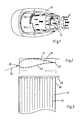
- FIG. 1 shows a perspective view of a turbine engine 10, the function of which is known and is therefore not explained in detail here.
- the pressure that prevails in a specific radial plane 12, 12a is to be measured.
- the pressure can be somewhat different along the circumference of the turbine, so that a pressure measurement at a certain point on the circumference may be delivers a disturbed measured value.
- a coated optical fiber 14, 14a is arranged along an essentially closed measuring path around the gas flow of the turbine engine in the radial plane 12, 12a. In this way, an average of the pressure in the radial plane 12, 12a is measured.
- an average of the temperature in a radial plane can be formed by means of a coated light guide, which is arranged along such a closed measuring path.
- FIGS. 2 and 3 Another application is shown in FIGS. 2 and 3.
- an wing of an aircraft is designated 16, the profile of which can be seen in FIG. 2.
- the wing 16 is flown in the direction of arrow 18. This results in a certain pressure distribution with a negative pressure on the upper side of the wing 16 from a stagnation point 20 to the rear edge 22 of the wing profile and a different pressure distribution on the underside.
- the lift results from the integral of the pressure distribution over the surface of the wing.
- This area integral of the pressure distribution is measured on the top of the wing 16 by a coated optical fiber 24, which, as can be seen from FIG. 3, is attached along a meandering measuring path on the top of the wing 16.
- the optical fiber 24 is thus evenly distributed over the top of the wing 16.
- a detector arrangement with which the optical fiber 24 is connected via further optical fibers 26, 28, integrally responds to the values of the optical property influenced by the pressure that occur along the optical fiber 24.
- a measured value is thus obtained which practically corresponds to the area integral of the pressure over the upper side of the wing 16.
- an area integral of the pressure over the underside of the wing 16 is measured by means of an optical fiber 30. The difference between these two measured values provides the buoyancy.
- phase shift which the light experiences in a section of the optical fiber does not only depend on the measured variable to be detected, e.g. pressure, but also from other physical parameters, e.g. the temperature depends.
- the latter physical measurement quantities are referred to here as disturbing measurement quantities.
- an optical fiber is only sensitive to a single physical measurement variable.
- the temperature dependence of the refractive index can sometimes not be neglected when measuring pressure.
- FIG. 4 shows an arrangement by means of which a line integral of only a first measured variable can be obtained unaffected by a second, disturbing measured variable even in such a case.
- Light from a light source is directed via a coupler 60 onto two optical fibers 62 and 64.
- the optical fibers 62 and 64 are used only for signal transmission and are designed so that they are influenced as little as possible by the measured variables.
- the optical fibers 62 and 64 are connected to optical fibers 68 and 70 via a coupler 66.
- An optical property of the optical fibers 68 and 70 is changed by a first measurement variable and a second measurement variable.
- the first measured variable is the pressure p
- the second measured variable is the temperature T.
- the refractive index n of the optical fibers 68 and 70 is changed locally.
- the phase of the light guided through the optical fibers 68 and 70 serves as a third measurement variable representing the line integral.
- the optical fibers 68 and 70 are provided with a sheathing, so that they are particularly suitable for the first measurement variable. eg the pressure, are sensitive., The pressure therefore represents the first measurement.
- the sensitivity for a second measurement for example the temperature, cannot be suppressed.
- the temperature therefore represents a disturbing measurement variable.
- the two optical fibers 68 and 70 are laid close together along a measuring path 72 so that they are exposed to the same pressure and temperature conditions.
- the optical fibers 69 and 70 are then connected again via a coupler 74 to optical fibers 76 and 78, which only serve for signal transmission.
- the optical fibers 76 and 78 are connected to a detector arrangement 82 via a coupler 80.
- the two optical fibers 68 and 70 are designed such that they have different sensitivities for the first and second measurement variable.
- n 68 and n 70 are the refractive indices obtained at a certain point in the optical fibers.
- the index p or T means the partial differentiation according to the size in question in the operating point p o , T o .
- the sheathing By a suitable choice of the sheathing, it can be ensured that, with different sensitivity of the two optical fibers 68 and 70 for the first measured variable, i.e. the pressure p, the sensitivities for the second, disturbing measured variable, ie the temperature T, are the same.
- the influence of the disturbing measured variable T disappears in a first approximation.
- the line integral over the first measured variable p is weighted with the difference A np of the sensitivities for this variable between the two optical fibers 68 and 70.
- the phase difference is formed in a Mach-Zehnder superposition of the light signals from the two optical fibers 60 and 70.
- phase other measured variables of the light guided through the optical fiber can also be modulated by changing the optical properties of the optical fibers, for example intensity, polarization or spectrum of the light.
- the optical property of the optical fiber which is dependent on the measured variable, can also be the optical birefringence, by means of which the polarization state of the light conducted through the optical fiber is changed.
Landscapes
- Physics & Mathematics (AREA)
- General Physics & Mathematics (AREA)
- Investigating Or Analysing Materials By Optical Means (AREA)
- Measuring Fluid Pressure (AREA)
- Testing Of Optical Devices Or Fibers (AREA)
- Length Measuring Devices By Optical Means (AREA)
Description
- Die Erfindung betrifft eine optische Faseranordnung zur Messung des Linienintegrals einer räumlich veränderlichen ersten Meßgröße längs eines vorgegebenen Meßweges, bei welcher sich der Meßweg über einen Bereich erstreckt, in welchem Änderungen der ersten Meßgröße zu erwarten sind.
- Es ist bekannt, Lichtleitfasern als Sensorelemente für physikalische Meßgrößen wie Druck oder Temperatur zu verwenden ("Optical Fibre Sensors" First International Conference, 25-28. April 1983, IEE Conf. Publication No 221 London). Es geht dabei stets um die Erfassung ortlich konstanter Meßgrößen. Meist wird die Lichtleitfaser auf einen Träger aufgewickelt, der sich nach Maßgabe einer zu messenden Meßgröße verformt. Zur Messung von Flüssigkeitsschwankungen wird beispielsweise die Lichtleitfaser außen auf eine zylindrische Membran aufgewickelt, die innen von dem zu erfassenden Flüssigkeitsdruck beaufschlagt ist, so daß auf die Lichtleitfaser ein mechanischer Zug ausgeübt wird. Zur Messung eines Magnetfeldes wird die Lichtleitfaser in entsprechender Weise auf einen magnetostriktiven Zylinder aufgewikkelt oder auf ein magnetostriktives Trägermaterial aufgeklebt. Es ist aber auch bekannt, daß eine einfache nackte Lichtleitfaser auf eine Druckänderung mit einer Phasenänderung des durch die Lichtleitfaser hindurchgehenden Lichts reagiert, wobei diese Phasenänderung proportional zu der Länge der Lichtleitfaser ist. Die Empfindlichkeit gegen Druckänderungen kann durch eine Ummantelung mit einem Material von höherer Kompressibilität als die des Fasermaterials wesentlich erhöht werden. Ebenso ist es bekannt, die Temperaturabhängigkeit der Brechzahl einer Lichtleitfaser und die thermische Ausdehnung der Lichtleitfaser für die Temperaturmessung auszunutzen.
- Die durch die Meßgröße beeinflußte optische Eigenschaft ist meist die optische Weglänge der Lichtleitfaser, d.h. die Phase des von einem Laser durch die Lichtleitfaser geleiteten Lichtes. Die durch Änderungen der Meßgröße hervorgerufenen Phasenverschiebungen werden mittels eines Interferometers mit einer Referenz-Lichtleitfaser in Signale umgesetzt. Die Interferometer sind beispielsweise Mach-Zehnder-Interferometer.
- Die ausgenutzte von der Meßgröße abhängige optische Eigenschaft der Lichtleitfaser kann aber auch die optische Doppelbrechung sein, durch welche der Polarisationszustand des durch die Lichtleitfaser geleiteten Lichts verändert wird.
- Es ist weiterhin bekannt, mittels einer Schleife aus einer Lichtleitfaser das Magnetfeld eines elektrischen Stromes zu messen (EP-OS 23 180). Auch dort handelt es sich um die Erfassung einer örtlich konstanten Meßgröße.
- Durch die DE-OS 2 934 794 ist ein mit Schleifen von Lichtleitfasern aufgebautes Gyroskop bekannt, durch welches Drehgeschwindigkeiten gegenüber dem inertialen Raum gemessen werden. Ein solches Gyroskop nutzt den Sagnac-Effekt aus. Bei einem geschlossenen Lichtweg ist im Falle einer Drehgeschwindigkeit im inertialen Raum die optische Weglänge für das "linksherum" laufende Licht verschieden von der optischen Weglänge für das "rechtsherum" laufende Licht. Aus der Phasendifferenz kann die Drehgeschwindigkeit bestimmt werden. Es werden dabei eine oder mehrere Schleifen der Lichtleitfaser gebildet, weil der Sagnac-Effekt proportional zu der von dem Lichtweg umschlossenen Fläche ist. Ähnliche Gyroskope sind auch in der eingangs erwähnten Literaturstelle "IEE Conf. Bulletin No. 221" beschrieben.
- Durch die DE-A-3 042 794 ist ein Lichtleiterhydrophon zur Messung von akustischen Druckschwankungen in einer Flüssigkeit bekannt. Das Gerät enthält einen von kohärentem Licht durchstrahlten Lichtleiter in Form einer spiralförmig auf einem flachen Trägermaterial angeordneten Flachspule. Es wird die Phasenverschiebung des Lichtes nach Durchgang durch den Lichtleiter gemessen. Die Phasenverschiebung schwankt mit der Frequenz der Druckschwankungen. Das Lichtleiterhydrophon ist richtungsempfindlich. Wenn die Ebene der Flachspule unter einem Winkel zur Wellenfront der akustischen Welle angeordnet ist, dann treten die Druckschwankungen in den verschiedenen Teilen der Flachspule zu unterschiedlichen Zeiten auf. Die Phasenverschiebungen des Lichtes, die in den Teilen der Flachspulen durch die Druckschwankungen hervorgerufen werden, mitteln sich teilweise heraus. Die Amplitude der Schwankung der Phasenverschiebung des austretenden Lichtes wird ein Maximum, wenn die Ebene der Flachspule mit der Ebene der Wellenfront der akustischen Welle zusammenfällt. Es sind Mittel vorgesehen, um die Flachspule auf das Maximum dieser Amplitude einzustellen, also nach der Schallquelle auszurichten.
- Bei dieser Anordnung geht es nicht um eine Messung eines Linienintegrals. Wie groß das Signal bei fehlausgerichteter Flachspule absolut ist, interessiert dort nicht. Es wird lediglich auf ein Maximum dieses Signals eingestellt. Auch werden Störeinflüsse wie Temperaturänderungen nicht berücksichtigt.
- Die DE-A-3 205 798 zeigt einen faseroptischen Phasenmodulator mit einer Lichtleitfaser, die auf einen rohrförmigen, piezokeramischen Körper aufgewickelt ist. Durch Anlegen einer elektrischen Spannung an den piezokeramischen Körper wird dieser verformt und dementsprechend die mechanische Spannung in der Lichtleitfaser verändert. Dabei tritt üblicherweise außer einer Phasenmodulation auch eine Polarisationsmodulation auf. Nach der Lehre der DE-A-3 205 798 wird durch Torsion der Lichtleitfaser in dem Phasenmodulator kein Polarisationszustand des durchlaufenden Lichtes bevorzugt. Ein solcher Phasenmodulator ist auch als Drucksensor anwendbar.
- Die DE-A-2 936 875 zeigt ein optisches Dehnungsmeßgerät bei welcher zwei Lichtleitfasern an verschiedenen Teilen eines zu vermessenden Gegenstandes angebracht sind. Bei einer Verformung des Gegenstandes werden die Lichtleitfasern unterschiedlich gedehnt.
- Die EP-A-0 038 401 zeigt ein ähnliches Verfahren zur Überwachung von physikalischen Zustandsänderungen von hochbelasteten Bauteilen. Dabei werden in die zu überwachenden Zonen der Bauteile Lichtleitfasern eingelagert und die optischen Eigenschaften der Lichtleitfasern beobachtet. Das sind praktisch auch optische Dehnungsmeßgeräte.
- Die EP-A-0 021 199 zeigt eine Anordnung mit zwei Lichtleitfasern, bei welcher das Licht in einer der Lichtleitfasern durch eine physikalische Grösse moduliert wird, beispielsweise eine Spannung, die an einem Kristall zur Änderung der Polarisationsrichtung des Lichtes anliegt. Es ist weiterhin bekannt, bei Turbinentriebwerken Drücke und Temperaturen an verschiedenen einzelnen Punkten durch Meßsonden zu messen. Ebenso ist es bekannt, Druck in einzelnen Punkten der Tragflächen eines Flugzeugs zu messen.
- Der Erfindung liegt die Aufgabe zugrunde, eine Vorrichtung zur Messung des Linienintegrals einer örtlich veränderlichen Messgrösse längs eines vorgegebenen Messweges zu schaffen.
- Der Erfindung liegt die speziellere Aufgabe zugrunde, eine solche Vorrichtung mit Hilfe von Lichtleitfasern zu realisieren.
- Erfindungsgemäss wird die Aufgabe gelöst durch
- (a) eine erste Lichtleitfaser, die längs dieses Messweges verlegt ist und aus einem Material mit einer optischen Eigenschaft besteht, welche an jeder Stelle längs des vorgegebenen Messweges von dieser ersten Messgrösse wenigstens näherungsweise als lineare Funktion der Messgrösse mit einem ersten Koeffizienten beeinflusst ist und welche ausserdem von einer zweiten, störenden Messgrösse beeinflusst ist,
- (b) Mittel zum Hindurchleiten von Licht durch die erste Lichtleitfaser als erstes Messlichtbündel
- (c) Kompensationsmittel mit einer zweiten, längs des Messweges verlegten Lichtleitfaser, bei welcher die besagte optische Eigenschaft durch die erste Messgrösse nach einer wenigstens näherungsweise linearen Funktion mit einem von dem ersten Koeffizienten verschiedenen zweiten Koeffizienten und ausserdem durch die zweite, störende Messgrösse beeinflusst sind und
- (d) Mittel zum Hindurchleiten von Licht durch die zweite Lichtleitfaser als zweites Messlichtbündel,
- (e) eine Detektoranordnung mit Mitteln, welche auf eine dritte Messgrösse des ersten und des zweiten Messlichtbündels ansprechen, die eine Funktion des Wegintegrals der Werte der besagten optischen Eigenschaft längs des vorgegebenen Messweges ist, längs welcher die Lichtleitfasern verlegt sind, und
- (f) Mittel zur Erzeugung eines Signals, welches das Linienintegral der ersten Messgrösse längs des Messweges, kompensiert hinsichtlich des Einflusses der zweiten Messgrösse darstellt, aus den dritten Messgrössen des ersten und des zweiten Messlichtbündels.
- Es kann auf diese Weise z.B. ein Mittelwert der Messgrösse über einen Messweg oder - bei z.B. mäanderförmiger Führung des Messweges - über eine Fläche gebildet werden. Wenn bei einer Druckmessung der Messweg mäanderförmig oder sonstwie gleichmässig über eine Fläche verteilt geführt wird, dann wird die Integration ein Mass für die durch den Druck auf die Fläche ausgeübte Kraft erhalten.
- Ausgestaltungen der Erfindung sind Gegenstand der abhängigen Anspruche.
- Die Erfindung ist nachstehend an einigen Ausführungsbeispielen unter Bezugnahme auf die zugehörigen Zeichnungen näher erläutert:
-
- Fig. 1 zeigt schematisch-perspektivisch die Anwendung der Vorrichtung zur Bildung eines Druckmittelwertes bei einem Turbinentriebwerk.
- Fig. 2 zeigt einen Schnitt durch eine Tragfläche eines Flugzeugs, auf weiche- druckempfindliche Lichtleitfasern in einem Mäandermuster zur Messung des Auftriebs auf der Ober- und Unterseite aufgebracht sind.
- Fig. 3 ist eine Draufsicht auf die Tragfläche von Fig. 2.
- Fig. 4 veranschaulicht die Unterdrückung einer störenden Messgrösse.
- In Fig. 1 ist perspektivisch ein Turbinentriebwerk 10 dargestellt, dessen Funktion bekannt und daher hier nicht im einzelnen erläutert ist. Es soll bei einem solchen Turbinentriebwerk der Druck gemessen werden, der in einer bestimmten Radialebene 12, 12a herrscht. Der Druck kann aber längs des Umfangs der Turbine etwas unterschiedlich sein, so dass eine Druckmessung an einer bestimmten Stelle des Umfangs u.U. einen gestörten Messwert liefert. Aus diesem Grunde ist eine ummantelte Lichtleitfaser 14, 14a längs eines im wesentlichen geschlossenen Messweges um den Gasstrom des Turbinentriebswerks herum in der Radialebene 12, 12a angeordnet. Es wird auf diese Weise ein Mittelwert des Drucks in der Radialebene 12, 12a gemessen.
- In ähnlicher Weise kann mittels eines ummantelten Lichtleiters, der längs eines solchen geschlossenen Messweges angeordnet ist, ein Mittelwert der Temperatur in einer Radialebene gebildet werden.
- Eine andere Anwendung ist in Fig. 2 und 3 dargestellt. Es ist dort eine Tragfläche eines Flugzeugs mit 16 bezeichnet, deren Profil aus Fig. 2 ersichtlich ist. Die Tragfläche 16 wird in Richtung des Pfeiles 18 angeströmt. Es ergibt sich dann auf der Oberseite der Tragfläche 16 von einem Staupunkt 20 bis zur Hinterkante 22 des Tragflächenprofils eine bestimmte Druckverteilung mit einem Unterdruck und auf der Unterseite eine andere Druckverteilung. Aus dem Integral der Druckverteilung über die Fläche der Tragfläche ergibt sich der Auftrieb. Dieses Flächenintegral der Druckverteilung wird auf der Oberseite der Tragfläche 16 durch eine ummantelte Lichtleitfaser 24 gemessen, die, wie aus Fig. 3 ersichtlich ist, längs eines mäanderförmigen Messweges auf der Oberseite der Tragfläche 16 angebracht ist. Die Lichtleitfaser 24 ist damit gleichmässig über die Oberseite der Tragfläche 16 verteilt. Eine Detektoranordnung, mit welcher die Lichtleitfaser 24 über weitere Lichtleitfasern 26, 28 verbunden ist, spricht integrierend auf die längs der Lichtleitfaser 24 auftretenden Werte der durch den Druck beeinflussten optischen Eigenschaft an. Es wird so ein Messwert gewonnen, der praktisch dem Flächenintegral des Druckes über die Oberseite der Tragfläche 16 entspricht. In entsprechender Weise wird mittels einer Lichtleitfaser 30 ein Flächenintegral des Druckes über die Unterseite der Tragfläche 16 gemessen. Die Differenz dieser beiden Messwerte liefert den Auftrieb.
- Beispiele solcher Schaltungen sind z.B. beschrieben in den Dokumenten Voges et al.: "Optical Phase and Amplitude Measurement by Single Sideband Homodyne Detection" in IEEE Journal QE-18 Seiten 124 ff und D. Eberhard und E. Voges "Fiber Gyroscope with Phase-Modulated Sindgle Sideband Detection" in "Optics Letters" Bd 9 No 1 Seiten 22 ff.
- Es wird nachstehend die Wirkungsweise der Vorrichtung nach dem Beispiel der Phasenmodulation erläutert. Es ist zu beachten, dass die Phasenverschiebung, welche das Licht in einem Abschnitt der Lichtleitfaser erfährt, nicht nur von der zu erfassenen Messgrösse, z.B. dem Druck, sondern auch von anderen physikalischen Messgrössen, z.B. der Temperatur, abhängt. Die letzteren physikalischen Messgrössen werden hier als störende Messgrössen bezeichnet.
- In manchen Fällen kann aber nicht erreicht werden, dass eine Lichtleitfaser nur für eine einzige physikalische Messgrösse empfindlich ist. Es kann beispielsweise manchmal bei einer Druckmessung die Temperaturabhängigkeit der Brechzahl nicht vernachlässigt werden.
- Fig. 4 zeigt eine Anordnung, durch welche auch in einem solchen Fall ein Linienintegral nur einer ersten Messgrösse unbeeinflusst von einer zweiten, störenden Messgrösse erhalten werden kann.
- Licht von einer Lichtquelle, z.B. einem Laser, wird über einen Koppler 60 auf zwei Lichtleitfasern 62 und 64 geleitet. Die Lichtleitfasern 62 und 64 dienen nur der Signalübertragung und sind so ausgeführt, dass sie von den Messgrössen möglichst wenig beeinflusst werden. Über einen Koppler 66 sind die Lichtleitfasern 62 und 64 mit Lichtleitfasern 68 bzw. 70 verbunden. Durch eine erste Messgrösse und eine zweite Messgrösse wird eine optische Eigenschaft der Lichtleitfasern 68 und 70 verändert. In dem beschriebenen Beispiel ist die erste Messgrösse der Druck p, die zweite Messgrösse die Temperatur T. Als "optische Eigenschaft" wird der Brechungsindex n der Lichtleitfasern 68 und 70 lokal verändert. Als eine das Linienintegral darstellende dritte Messgrösse dient die Phase des durch die Lichtleitfasern 68 bzw. 70 geführten Lichtes. Die Lichtleitfasern 68 und 70 sind mit einer Ummantelung versehen, so dass sie besonders for die erste Messgrösse. z.B. den Druck, empfindlich sind., Der Druck stellt somit die erste Messgrösse dar. Die Empfindlichkeit für eine zweite Messgrösse, z.B. die Temperatur, lässt sich aber nicht unterdrücken. Die Temperatur stellt somit eine störende Messgrösse dar. Die beiden Lichtleitfasern 68 und 70 sind dicht nebeneinander längs eines Messweges 72 verlegt, so dass sie gleichen Druck- und Temperaturverhältnissen ausgesetzt sind. Über einen Koppler 74 sind die Lichtleitfasern 69 und 70 dann wieder mit Lichtleitfasern76 bzw. 78 verbunden, die nur der Signalübertragung dienen. Die Lichtleitfasern 76 und 78 sind über einen Koppler 80 mit einer Detektoranordnung 82 verbunden.
- Die beiden Lichtleitfasern 68 und 70 sind so ausgebildet, dass sie unterschiedliche Empfindlichkeiten für die erste und zweite Messgrösse besitzen.
- Die beschriebene Anordnung arbeitet wie folgt:
- Die erste Messgrösse sei der Druck p, zweite störende Messgrösse sei die Temperatur T. Gemäss Gleichung (2) gilt dann für die Lichtleitfaser 68


- Dabei sind n68 und n70 die in einem bestimmten Punkt der Lichtleitfasern erhaltenen Brechzahlen. Der Index p oder T bedeutet die partielle Differentiation nach der betreffenden Größe im Arbeitspunkt po, To.
- Durch geeignete Wahl der Ummantelung kann dafür gesorgt werden, daß bei unterschiedlicher Empfindlichkeit der beiden Lichtleitfasern 68 und 70 für die erste Meßgröße, d.h. den Druck p, die Empfindlichkeiten für die zweite, störende Meßgröße, also die Temperatur T, gleich sind.
- Es ist also


- Die Differenz der auf integrierten Phasenänderungen, also die Differenz der "dritten Meßgrößen", ist dann

- In der Differenz verschwindet der Einfluß der störenden Meßgröße T in erster Näherung. Das Linienintegral über die erste Meßgröße p wird gewichtet mit der Differenz A np der Empfindlichkeiten für diese Größe zwischen den beiden Lichtleitfasern 68 und 70. Die Phasendifferenzbildung erfolgt in einer Mach-Zehnder-Überlagerung der Lichtsignale aus den beiden Lichtleitfasern 60 und 70.
- Statt der Phase können auch andere Meßgrößen des durch die Lichtleitfaser geleiteten Lichts durch die Änderung der optischen Eigenschaften der Lichtleitfasern moduliert werden, beispielsweise Intensität, Polarisation oder Spektrum des Lichts.
- Die ausgenutzte von der Meßgröße abhängige optische Eigenschaft der Lichtleitfaser kann auch die optische Doppelbrechung sein, durch welche der Polarisationszustand des durch die Lichtleitfaser geleiteten Lichts verändert wird.
Claims (8)
Applications Claiming Priority (2)
| Application Number | Priority Date | Filing Date | Title |
|---|---|---|---|
| DE19843420172 DE3420172A1 (de) | 1984-05-30 | 1984-05-30 | Vorrichtung zur messung des linienintegrals einer oertlich veraenderlichen messgroesse |
| DE3420172 | 1984-05-30 |
Publications (3)
| Publication Number | Publication Date |
|---|---|
| EP0163022A2 EP0163022A2 (de) | 1985-12-04 |
| EP0163022A3 EP0163022A3 (en) | 1989-07-19 |
| EP0163022B1 true EP0163022B1 (de) | 1991-08-21 |
Family
ID=6237222
Family Applications (1)
| Application Number | Title | Priority Date | Filing Date |
|---|---|---|---|
| EP19850102911 Expired - Lifetime EP0163022B1 (de) | 1984-05-30 | 1985-03-14 | Vorrichtung zur Messung des Linienintegrals einer örtlich veränderlichen Messgrösse |
Country Status (2)
| Country | Link |
|---|---|
| EP (1) | EP0163022B1 (de) |
| DE (2) | DE3420172A1 (de) |
Families Citing this family (5)
| Publication number | Priority date | Publication date | Assignee | Title |
|---|---|---|---|---|
| US4845357A (en) * | 1988-02-11 | 1989-07-04 | Simmonds Precision Products, Inc. | Method of actuation and flight control |
| CA2055790A1 (en) * | 1991-01-04 | 1992-07-05 | Victor Vali | System for accurately detecting changes in temperature and pressure |
| GB9314487D0 (en) * | 1993-07-12 | 1993-08-25 | Secr Defence | Sensor system |
| EP0692705B1 (de) * | 1994-07-16 | 1998-03-11 | Felten & Guilleaume Energietechnik AG | Verfahren zur Auswertung optisch rückgestreuter Signale zur Bestimmung eines streckenabhängigen Messprofils eines Rückstreumediums |
| CZ2015154A3 (cs) * | 2015-03-05 | 2016-04-20 | Vysoká Škola Báňská - Technická Univerzita Ostrava | Optovláknový interferometrický senzor pro monitorování dopravního provozu |
Family Cites Families (7)
| Publication number | Priority date | Publication date | Assignee | Title |
|---|---|---|---|---|
| US4191470A (en) * | 1978-09-18 | 1980-03-04 | Honeywell Inc. | Laser-fiber optic interferometric strain gauge |
| US4334781A (en) * | 1979-06-08 | 1982-06-15 | Tokyo Shibaura Denki Kabushiki Kaisha | Optical sensing system |
| FR2461956A1 (fr) * | 1979-07-24 | 1981-02-06 | Thomson Csf | Dispositif interferometrique de mesure de courant electrique a fibre optique |
| DE2934794A1 (de) * | 1979-08-29 | 1981-03-19 | Licentia Patent-Verwaltungs-Gmbh, 6000 Frankfurt | Verfahren zur messung absoluter drehungen und anordnung zur durchfuehrung des verfahrens |
| DE3015391C2 (de) * | 1980-04-22 | 1986-12-04 | Philips Kommunikations Industrie AG, 8500 Nürnberg | Verfahren zur Kontrolle von zu überwachenden physikalischen Belastungsgrößen an und/oder in einem Bauteil |
| DE3042794C2 (de) * | 1980-11-13 | 1983-03-24 | Messerschmitt-Bölkow-Blohm GmbH, 8000 München | Lichtleiterhydrofon |
| DE3205798A1 (de) * | 1982-02-18 | 1983-08-25 | Licentia Patent-Verwaltungs-Gmbh, 6000 Frankfurt | Faseroptischer phasenmodulator |
-
1984
- 1984-05-30 DE DE19843420172 patent/DE3420172A1/de not_active Withdrawn
-
1985
- 1985-03-14 EP EP19850102911 patent/EP0163022B1/de not_active Expired - Lifetime
- 1985-03-14 DE DE8585102911T patent/DE3583821D1/de not_active Expired - Fee Related
Also Published As
| Publication number | Publication date |
|---|---|
| DE3583821D1 (de) | 1991-09-26 |
| EP0163022A2 (de) | 1985-12-04 |
| DE3420172A1 (de) | 1985-12-05 |
| EP0163022A3 (en) | 1989-07-19 |
Similar Documents
| Publication | Publication Date | Title |
|---|---|---|
| EP0856737B1 (de) | Magneto-optischer Stromsensor | |
| DE69814568T2 (de) | Bourdon-manometer mit integrierten optischen dehnungsfühlern zur messung von zug- oder druckdehnungen | |
| EP0153997B1 (de) | Verfahren zur Kraftmessung mit Hilfe der spannungsinduzierten Doppelbrechung in einem Monomode-Lichtleiter und Messanordnung zur Durchführung des Verfahrens | |
| DE69801435T2 (de) | Schwingungsfehlerverminderungsservo für faseroptischen kreisel | |
| DE69608461T2 (de) | Stromfühler mit kompensation für die temperaturabhängigkeit der verdet-konstante | |
| EP0487450B1 (de) | Verfahren und Einrichtungen zur faseroptischen Kraftmessung | |
| DE68927644T2 (de) | Verfahren zum optischen fühlen | |
| DE3138075C2 (de) | ||
| DE3883445T2 (de) | Interferometersensor mit zeitaufgelösten Messungen. | |
| DE69828788T2 (de) | Integriertes optisches wellenleiterbauelement | |
| DE102013101432B4 (de) | Faseroptischer Beschleunigungssensor mit Hebel | |
| DE19703128A9 (de) | Magnetooptischer Stromsensor | |
| EP0267381B1 (de) | Einrichtung und Verwendung eines Lichtwellenleiter-Sensors für die Messung minimaler Dehnungen | |
| DE102019132522A1 (de) | Fabry-Perot-Temperatursensor | |
| DE102018104953B4 (de) | Messvorrichtung und Verfahren zum Bestimmen einer physikalischen Messgröße | |
| DE102008044810B4 (de) | Faseroptisches Interferometer und Verfahren zur Bestimmung physikalischer Zustandsgrößen im Innern einer Faserspule eines faseroptischen Interferometers | |
| DE19701221C1 (de) | Verfahren zur Temperaturkompensation von Meßsignalen eines faseroptischen Sensors | |
| DE3205798C2 (de) | ||
| DE3611119C1 (de) | Sensoranordnung | |
| EP0163022A2 (de) | Vorrichtung zur Messung des Linienintegrals einer örtlich veränderlichen Messgrösse | |
| DE3040514A1 (de) | Verfahren und anordnung zur signalauswertung eines lichtleitfaserrotationssensors | |
| DE2521319B2 (de) | Piezooptischer Meßwandler | |
| EP1284425B1 (de) | Verfahren und Vorrichtung zur Störgrössenkompensation eines optischen Sensors | |
| DE68903616T2 (de) | Fiberoptische messeinrichtung, gyrometer, navigations- und stabilisationssystem. | |
| DE102017201523A1 (de) | Faseroptische Erfassungseinrichtung sowie Verfahren zum Betreiben einer solchen faseroptischen Erfassungseinrichtung |
Legal Events
| Date | Code | Title | Description |
|---|---|---|---|
| PUAI | Public reference made under article 153(3) epc to a published international application that has entered the european phase |
Free format text: ORIGINAL CODE: 0009012 |
|
| AK | Designated contracting states |
Designated state(s): DE FR GB |
|
| PUAL | Search report despatched |
Free format text: ORIGINAL CODE: 0009013 |
|
| AK | Designated contracting states |
Kind code of ref document: A3 Designated state(s): DE FR GB |
|
| RHK1 | Main classification (correction) |
Ipc: G01D 5/26 |
|
| 17P | Request for examination filed |
Effective date: 19900115 |
|
| 17Q | First examination report despatched |
Effective date: 19900713 |
|
| GRAA | (expected) grant |
Free format text: ORIGINAL CODE: 0009210 |
|
| AK | Designated contracting states |
Kind code of ref document: B1 Designated state(s): DE FR GB |
|
| REF | Corresponds to: |
Ref document number: 3583821 Country of ref document: DE Date of ref document: 19910926 |
|
| GBT | Gb: translation of ep patent filed (gb section 77(6)(a)/1977) | ||
| ET | Fr: translation filed | ||
| PLBE | No opposition filed within time limit |
Free format text: ORIGINAL CODE: 0009261 |
|
| STAA | Information on the status of an ep patent application or granted ep patent |
Free format text: STATUS: NO OPPOSITION FILED WITHIN TIME LIMIT |
|
| 26N | No opposition filed | ||
| PGFP | Annual fee paid to national office [announced via postgrant information from national office to epo] |
Ref country code: FR Payment date: 19930218 Year of fee payment: 9 |
|
| PGFP | Annual fee paid to national office [announced via postgrant information from national office to epo] |
Ref country code: GB Payment date: 19930301 Year of fee payment: 9 |
|
| PGFP | Annual fee paid to national office [announced via postgrant information from national office to epo] |
Ref country code: DE Payment date: 19930525 Year of fee payment: 9 |
|
| PG25 | Lapsed in a contracting state [announced via postgrant information from national office to epo] |
Ref country code: GB Effective date: 19940314 |
|
| GBPC | Gb: european patent ceased through non-payment of renewal fee |
Effective date: 19940314 |
|
| PG25 | Lapsed in a contracting state [announced via postgrant information from national office to epo] |
Ref country code: FR Effective date: 19941130 |
|
| PG25 | Lapsed in a contracting state [announced via postgrant information from national office to epo] |
Ref country code: DE Effective date: 19941201 |
|
| REG | Reference to a national code |
Ref country code: FR Ref legal event code: ST |