EP0162584A2 - Schleuderstrahlmaschine - Google Patents
Schleuderstrahlmaschine Download PDFInfo
- Publication number
- EP0162584A2 EP0162584A2 EP85302789A EP85302789A EP0162584A2 EP 0162584 A2 EP0162584 A2 EP 0162584A2 EP 85302789 A EP85302789 A EP 85302789A EP 85302789 A EP85302789 A EP 85302789A EP 0162584 A2 EP0162584 A2 EP 0162584A2
- Authority
- EP
- European Patent Office
- Prior art keywords
- machine
- abrasive
- particles
- enclosure
- throwing
- Prior art date
- Legal status (The legal status is an assumption and is not a legal conclusion. Google has not performed a legal analysis and makes no representation as to the accuracy of the status listed.)
- Withdrawn
Links
- 239000002245 particle Substances 0.000 claims abstract description 51
- 238000007789 sealing Methods 0.000 claims description 8
- 239000011236 particulate material Substances 0.000 claims description 3
- 238000005192 partition Methods 0.000 description 16
- 239000000463 material Substances 0.000 description 4
- 235000004443 Ricinus communis Nutrition 0.000 description 2
- 240000000528 Ricinus communis Species 0.000 description 2
- 238000005422 blasting Methods 0.000 description 2
- 239000003082 abrasive agent Substances 0.000 description 1
- 230000003247 decreasing effect Effects 0.000 description 1
- 239000012530 fluid Substances 0.000 description 1
Images
Classifications
-
- B—PERFORMING OPERATIONS; TRANSPORTING
- B24—GRINDING; POLISHING
- B24C—ABRASIVE OR RELATED BLASTING WITH PARTICULATE MATERIAL
- B24C3/00—Abrasive blasting machines or devices; Plants
- B24C3/02—Abrasive blasting machines or devices; Plants characterised by the arrangement of the component assemblies with respect to each other
- B24C3/06—Abrasive blasting machines or devices; Plants characterised by the arrangement of the component assemblies with respect to each other movable; portable
- B24C3/065—Abrasive blasting machines or devices; Plants characterised by the arrangement of the component assemblies with respect to each other movable; portable with suction means for the abrasive and the waste material
- B24C3/067—Self-contained units for floorings
Definitions
- This invention relates to shot blasting or abrasive throwing machines, more particularly to such machines for blasting a surface, especially a horizontal or inclined surface with an abrasive in order to clean the surface or remove a layer of material from the surface.
- Such abrasive throwing machines typically include an abrasive projector mounted within a housing and capable of being fed with abrasive particles, and projecting those abrasive particles through an opening in the housing to impinge at an inclined angle upon the surface being treated. Most of the particles rebound at an inclined angle from this surface and as a result enter a separate housing, normally in the form of an elongate duct, which defines a return path for the spent abrasive particles which travel along the duct to a position where they can be fed again to the particle projector.
- the inclination and length of the return duct is such that the machine as a whole extends a significant distance horiziontally beyond the opening towards which the abrasive particles are projected.
- the surface being treated is a floor bounded by vertical walls it is only possible to treat the floor to within a certain distance of the bounding walls as limited by the extent of projection of the machine horizontally beyond the aforementioned opening.
- an abrasive throwing machine comprising an enclosure housing particle abrasive projecting means and means for feeding abrasive particles to said projecting means, said projecting means being arranged to project particles through an opening in the enclosure against the surface to be treated whereby rebounding particles return within said enclosure, said projecting means and the wall of said enclosure being arranged so that at least a portion of said rebounding particles are directed along a path extending from said projecting means, adjacent said enclosure wall, to said feed means.
- said particle projecting means are in the form of a single abrasive throwing wheel and more preferably said throwing wheel is mounted with its axis parallel to the plane of said opening.
- said machine is arranged to travel in a direction at right angles to the axis of the throwing wheel, and it is also preferred that the throwing wheel extends across substantially the full width of the enclosure. More preferably the throwing wheel is in the form of a central hub having extending radially therefrom a number of paddles, for instance four such circumferentially spaced apart paddles. Such a throwing wheel is known as a batter wheel.
- the batter wheel is mounted directly over the opening and the rotary motion of the batter wheel not only acts to project particles through the opening but also assists in projecting spent particles in a direction towards said feed means, said particles being guided in said direction by the forward end wall of said enclosure.
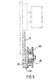
- an abrasive throwing machine includes means for feeding abrasive particles to a throwing wheel comprising valve means in which the valve member is in the form of a quadrant mounted so as to be pivotal from a first position with its curved sealing surface sealing a feed hole for the particulate material through a range of positions in which the feed hole is opened to a progressively larger extent.
- an abrasive throwing machine is provided with mobility means in the form of a caterpillar track arrangement down each side of the machine.
- Previously abrasive throwing machines have been provided with a single pair of large wheels normally located at the front of the machine and a smaller pair of wheels or castors at the rear of the machine. With such a conventional arrangement it is necessary that the bottom of the housing of the machine be positioned perhaps about 11 ⁇ 2 or 2 inches above the floor. Unless such a clearance is provided, the housing will tend to ground over any significant unevenness of the floor.
- a sealing side plate is provided, which side plate is mounted on the axles of at least some of the wheels forming part of the caterpillar track arrangement.
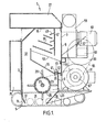
- an abrasive throwing machine 1 includes housing 3 carrying various items of equipment (to be mentioned hereinafter) and being mounted on caterpillar track arrangements 5 for powered movement in a forward or rearward direction (to the left or right respectively in Figure 1).
- Housing 3 includes front and rear walls 7 and 9, side walls 11 and 13, top 15 and a part base formed by inclined extensions 17 and 19 of front and rear walls 7 and 9 respectively.
- Inclined walls 17 and 19 together with side walls 11 and 13 define an opening 21 which extends substantially the full width of the machine and which, in use, overlies an area of floor which is being treated by the machine.
- a batter wheel 23 which includes a hollow drum 25 arranged about an axle 27. Extending radially outwardly from drum 23 are four circumferentially spaced apart paddles 29. Each paddle 29 extends substantially the full width of the housing 3 and may comprise a radially inner lug on which is mounted an outer blade, the latter being, 'in use, subject to wear and being replaceable.
- the batter wheel 23 is located with its axle 27 vertically above opening 21 and offset rearwardly from the centre of opening 21.
- the batter wheel 23 is arranged to be driven by motor 31 located rearwardly of the housing by means of a drive belt 33.
- the batter wheel blades sweep out a cylindrical space extending from a position rearwardly close to rear wall 9 and inclined wall 19 of housing 3 forwardly to a position just rearward of the forward limit of space 21 and about a paddle width rearward of front wall 7.
- Above the batter wheel 23 there is mounted within housing 3 a partition 35 which extends from a position close to rear wall 9 forwardly and upwardly above batter wheel 23 and, at its most forward end, it extends vertically upwardly for a short distance to define a passageway 33.
- a feed hole 39 extending substantially the full width of the machine.
- Forwardly and rearwardly feed hole 39 is defined by accurately machined valve seating members 41 and 43 and arranged above feed hole 39 is a valve member 45 in the form of a quadrant capable of pivotal movement from the position shown in Figure 1 where the feed hole is closed to a position where the feed hole 39 is completely disclosed or to any position therebetween.
- the position of valve member 45 is controlled by the operator of the machine and in an open position abrasive particles which have collected in the hopper-like space between partition 35 and rear wall 9 are allowed to drop through feed hole 39 and come into contact with thepaddles 29 of batter wheel 23.
- batter wheel 23 causes the abrasive particles to be thrown by the paddles 29 along an initial path defined by the batter wheel 23 and inclined wall 19 towards opening 21. It will be appreciated that, consequently, the abrasive particles are projected through space 21 so as to impinge upon an area of floor located below space 21 at an inclined angle thereto. Most of the abrasive particles rebound from the floor, again at an inclined angle,in a direction towards front wall 7. Together with these rebounding abrasive particles will be other particles of various sizes removed from the floor as a result of the abrasive action.
- a further partition in the form of screen 53 Located below vertical wall 47 and the lowermost partition 51 is a further partition in the form of screen 53.
- This screen extends from a rearmost position at rear wall 9 upwardly and forwardly to a foremost position close to the top of the vertical section of partition 35 so that below screen 53 there is the previously mentioned hopper-like arrangement whereby material passing through screen 53 accumulates naturally above feed hole 39.
- the screen is such that material passing through it will be mainly fine abrasive particles.
- the larger particles which have been carried upwardly from the floor being treated will on the whole not pass through the screen but rather slide down the screen and pass out of the housing 3 into outlet duct 55.
- the base of outlet duct 55 is inclined so that these particles will tend to slide towards the side of the machine into a suitable receptacle.
- abrasive particles may be supplied by a hopper mounted on the outside of the rear wall 9 (indicated by dotted lines 57) into the housing above screen 53.
- a fan 59 driven by motor 61 is mounted at the rear of the machine and causes air to be sucked through holes located in the upper part of rear wall 9.
- air is drawn in to the housing below inclined wall 19 at the base of the housing and follows a path within the housing upwardly through passage 37 over the various partitions located above screen 53 towards the fan 59.
- batter wheel 23 which carries rebounding abrasive particles and other particles removed from the floor upwardly to the various screens located above the batter wheel.
- the machine also carries a hydraulic pump 63 driven by a drive belt 65 extending between pulleys 67 and 69 and which in turn delivers hydraulic power to hydraulic motors 71 and 73 mounted at positions near the base of the machine and appropriate to convey drive to the drive wheels of caterpillar track arrangements 5.
- a hydraulic fluid tank 75 is mounted at the front of the machine and a housing 77 containing the various electrical controls is mounted directly above housing 3.
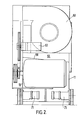
- a pulley 83 of one of the caterpillar track arrangements 5 is mounted on stub axle 85 fixed to plate 81. Also mounted on axle 85 is side seal plate 87. This plate extends the full length of the housing and is provided with a series of oblong holes (with their major axes vertical), each stub axle 85 passing through one of these holes. Plate 87 is loosely mounted, the oblong holes allowing the plate to ride up and down on the stub axles of the caterpillar pulleys in order to accommodate the unevenness of the ground and yet provide good sealing between the interior of the housing and the outside.
- the caterpillar track and sealing arrangement located on each side of the machine are such that together they extend only a short distance from the sides of the machine and thereby allow the machine to be used much closer to a bounding vertical wall than conventional machines. This can perhaps best be seen in Figure 2 where the right hand edge of the machine is located only a short distance outwardly of the side wall 11 of the housing.
- the forward extent of the machine as measured from the forward edge of space 21 is located much closer to space 21 than would be the case where a separate return duct is provided for spent particles. Even with the hydraulic tank mounted on the front of forward wall 7 of the housing, a floor can be treated to a position much closer to a bounding vertical wall than was possible hitherto.
Landscapes
- Engineering & Computer Science (AREA)
- Environmental & Geological Engineering (AREA)
- Mechanical Engineering (AREA)
- Finish Polishing, Edge Sharpening, And Grinding By Specific Grinding Devices (AREA)
- Crushing And Pulverization Processes (AREA)
Applications Claiming Priority (2)
| Application Number | Priority Date | Filing Date | Title |
|---|---|---|---|
| GB848410555A GB8410555D0 (en) | 1984-04-25 | 1984-04-25 | Abrasive throwing machine |
| GB8410555 | 1984-04-25 |
Publications (2)
| Publication Number | Publication Date |
|---|---|
| EP0162584A2 true EP0162584A2 (de) | 1985-11-27 |
| EP0162584A3 EP0162584A3 (de) | 1986-08-27 |
Family
ID=10560057
Family Applications (1)
| Application Number | Title | Priority Date | Filing Date |
|---|---|---|---|
| EP85302789A Withdrawn EP0162584A3 (de) | 1984-04-25 | 1985-04-22 | Schleuderstrahlmaschine |
Country Status (2)
| Country | Link |
|---|---|
| EP (1) | EP0162584A3 (de) |
| GB (1) | GB8410555D0 (de) |
Cited By (3)
| Publication number | Priority date | Publication date | Assignee | Title |
|---|---|---|---|---|
| GB2203071A (en) * | 1987-04-03 | 1988-10-12 | Williams N L Eng Ltd | Apparatus for abrasive treatment of surfaces |
| GB2239412A (en) * | 1987-04-03 | 1991-07-03 | Williams N L Eng Ltd | Apparatus for abrasive treatment of surfaces |
| US8550881B2 (en) | 2009-11-16 | 2013-10-08 | Pangborn Corporation | Vane, mounting assembly and throwing wheel apparatus having a locking member tapered in two planes |
Family Cites Families (9)
| Publication number | Priority date | Publication date | Assignee | Title |
|---|---|---|---|---|
| GB839265A (en) * | 1957-11-02 | 1960-06-29 | Norman Ives Ashworth | Improvements in abrasive blasting appliances |
| US3788010A (en) * | 1972-02-28 | 1974-01-29 | Nelson R | Apparatus for treatment of vertically disposed surfaces |
| US3877175A (en) * | 1973-05-24 | 1975-04-15 | Wheelabrator Frye Inc | Mobile surface treating apparatus |
| US3981104A (en) * | 1975-03-20 | 1976-09-21 | Texstar, Inc. | Grit blasting machine and method |
| JPS52114394U (de) * | 1975-12-18 | 1977-08-30 | ||
| US4132039A (en) * | 1977-02-10 | 1979-01-02 | Enviro-Blast International | Abrasive blasting apparatus |
| US4092942A (en) * | 1977-07-05 | 1978-06-06 | Magster Company | Mobile shot blasting apparatus for shot blasting the bottom of a ship or the like |
| DE2904093C2 (de) * | 1979-02-03 | 1985-07-25 | Heinrich Schlick KG, GmbH & Co, 4402 Greven | Einrichtung zum Reinigen von Oberflächen großflächiger Werksstücke mit einem Strahlmittel |
| US4416092A (en) * | 1981-11-24 | 1983-11-22 | Nelson Robert T | Cleaning apparatus |
-
1984
- 1984-04-25 GB GB848410555A patent/GB8410555D0/en active Pending
-
1985
- 1985-04-22 EP EP85302789A patent/EP0162584A3/de not_active Withdrawn
Cited By (5)
| Publication number | Priority date | Publication date | Assignee | Title |
|---|---|---|---|---|
| GB2203071A (en) * | 1987-04-03 | 1988-10-12 | Williams N L Eng Ltd | Apparatus for abrasive treatment of surfaces |
| GB2239412A (en) * | 1987-04-03 | 1991-07-03 | Williams N L Eng Ltd | Apparatus for abrasive treatment of surfaces |
| GB2239412B (en) * | 1987-04-03 | 1991-11-27 | Williams N L Eng Ltd | Methods of treating surfaces |
| GB2203071B (en) * | 1987-04-03 | 1991-11-27 | Williams N L Eng Ltd | Apparatus for treating surfaces |
| US8550881B2 (en) | 2009-11-16 | 2013-10-08 | Pangborn Corporation | Vane, mounting assembly and throwing wheel apparatus having a locking member tapered in two planes |
Also Published As
| Publication number | Publication date |
|---|---|
| GB8410555D0 (en) | 1984-05-31 |
| EP0162584A3 (de) | 1986-08-27 |
Similar Documents
| Publication | Publication Date | Title |
|---|---|---|
| US4433511A (en) | Mobile abrasive blasting surface treating apparatus | |
| DE2543984C3 (de) | Verfahrbare Schleuderstrahlvorrichtung für das Bearbeiten horizontaler Flächen | |
| US4121388A (en) | Abrasive surface treating device | |
| CA1141550A (en) | Apparatus for the treatment of surfaces with particulate abrasive | |
| US3887141A (en) | Impact-attrition mill utilizing air flow | |
| US3034262A (en) | Resurfacing and finishing machine | |
| KR102056693B1 (ko) | 페인팅 설비 및 페인팅 설비를 동작하는 방법 | |
| US7219964B2 (en) | Milling machine as well as method for working ground surfaces | |
| CA1191030A (en) | Shot blasting machinery | |
| US4753052A (en) | Surface blasting apparatus | |
| DE3116264A1 (de) | Vorrichtung zur behandlung von oberflaechen | |
| US4364823A (en) | Apparatus for separating abrasive blasting media from debris | |
| GB2199772A (en) | Sieving machine with sieve cleaning | |
| GB2203073A (en) | Apparatus for abrasive treatment of surfaces | |
| US4382352A (en) | Apparatus for cleaning surfaces, including means for separating debris and abrasive material | |
| EP0162584A2 (de) | Schleuderstrahlmaschine | |
| CA1322103C (en) | Surface cleaner | |
| US5885141A (en) | Portable blast wheel cleaning machine | |
| EP0518102B1 (de) | Schleuderstrahlvorrichtung | |
| US5205084A (en) | Flat-walled apparatus and housing for treating horizontal surfaces | |
| US2026426A (en) | Cutter mill | |
| NL8100299A (nl) | Inrichting voor het behandelen van de bovenzijde van een horizontaal of hellend oppervlak. | |
| US4841681A (en) | Surface blasting apparatus | |
| US5231806A (en) | Air sweep system for mobile surface abrading apparatus | |
| US3269532A (en) | Screen and pneumatic separator |
Legal Events
| Date | Code | Title | Description |
|---|---|---|---|
| PUAI | Public reference made under article 153(3) epc to a published international application that has entered the european phase |
Free format text: ORIGINAL CODE: 0009012 |
|
| AK | Designated contracting states |
Designated state(s): AT BE CH DE FR GB IT LI LU NL SE |
|
| PUAL | Search report despatched |
Free format text: ORIGINAL CODE: 0009013 |
|
| AK | Designated contracting states |
Kind code of ref document: A3 Designated state(s): AT BE CH DE FR GB IT LI LU NL SE |
|
| 17P | Request for examination filed |
Effective date: 19870127 |
|
| 17Q | First examination report despatched |
Effective date: 19880301 |
|
| STAA | Information on the status of an ep patent application or granted ep patent |
Free format text: STATUS: THE APPLICATION IS DEEMED TO BE WITHDRAWN |
|
| 18D | Application deemed to be withdrawn |
Effective date: 19880912 |
|
| RIN1 | Information on inventor provided before grant (corrected) |
Inventor name: BOULTON, GEORGE FREDERICK CHARLES |