EP0162365A2 - Verfahren und Gerät zur Steuerung des Luft-Kraftstoffverhältnisses in einer Innenbrennkraftmaschine - Google Patents
Verfahren und Gerät zur Steuerung des Luft-Kraftstoffverhältnisses in einer Innenbrennkraftmaschine Download PDFInfo
- Publication number
- EP0162365A2 EP0162365A2 EP85105502A EP85105502A EP0162365A2 EP 0162365 A2 EP0162365 A2 EP 0162365A2 EP 85105502 A EP85105502 A EP 85105502A EP 85105502 A EP85105502 A EP 85105502A EP 0162365 A2 EP0162365 A2 EP 0162365A2
- Authority
- EP
- European Patent Office
- Prior art keywords
- fuel ratio
- air
- engine
- aimed
- throttle valve
- Prior art date
- Legal status (The legal status is an assumption and is not a legal conclusion. Google has not performed a legal analysis and makes no representation as to the accuracy of the status listed.)
- Granted
Links
Images


Classifications
-
- F—MECHANICAL ENGINEERING; LIGHTING; HEATING; WEAPONS; BLASTING
- F02—COMBUSTION ENGINES; HOT-GAS OR COMBUSTION-PRODUCT ENGINE PLANTS
- F02D—CONTROLLING COMBUSTION ENGINES
- F02D41/00—Electrical control of supply of combustible mixture or its constituents
- F02D41/02—Circuit arrangements for generating control signals
- F02D41/14—Introducing closed-loop corrections
- F02D41/1438—Introducing closed-loop corrections using means for determining characteristics of the combustion gases; Sensors therefor
- F02D41/1486—Introducing closed-loop corrections using means for determining characteristics of the combustion gases; Sensors therefor with correction for particular operating conditions
- F02D41/1488—Inhibiting the regulation
- F02D41/149—Replacing of the control value by an other parameter
-
- F—MECHANICAL ENGINEERING; LIGHTING; HEATING; WEAPONS; BLASTING
- F02—COMBUSTION ENGINES; HOT-GAS OR COMBUSTION-PRODUCT ENGINE PLANTS
- F02D—CONTROLLING COMBUSTION ENGINES
- F02D41/00—Electrical control of supply of combustible mixture or its constituents
- F02D41/02—Circuit arrangements for generating control signals
- F02D41/14—Introducing closed-loop corrections
- F02D41/1401—Introducing closed-loop corrections characterised by the control or regulation method
- F02D41/1406—Introducing closed-loop corrections characterised by the control or regulation method with use of a optimisation method, e.g. iteration
Definitions
- the present invention relates to a method and apparatus for feedback control of the air-fuel ratio in an internal combustion engine.
- a lean burn system As measures taken against exhaust gas pollution and fuel consumption, a lean burn system has recently been developed. According to this lean burn system, a lean mixture sensor is provided for generating an analog current in proportion to the air-fuel mixture on the lean side in an exhaust pipe of an engine. Thus, the feedback of the air-fuel ratio of the engine can be controlled by using the analog output of the lean mixture sensor, thereby attaining an arbitrary air-fuel ratio on the lean side.
- Another object is to reduce the torque fluctuation in the driving mode at a low altitude location even when rapid torque change in a driving mode for a high altitude location is avoided.
- the feedback of the air-fuel ratio of the engine is controlled so that the air-fuel ratio is brought close to a first base air-fuel ratio.
- the opening of the throttle valve is egual to or larger than the relatively small definite value and is smaller than a relatively large definite value
- feedback of the air-fuel ratio of the engine is controlled so that the controlled air-fuel ratio is brought close to a second base air-fuel ratio on the rich side with respect to the first base air-fuel ratio.
- the opening of the throttle valve is equal to or larger than the relatively large definite value
- the air-fuel ratio of the engine is controlled to be a power fuel increment air-fuel ratio.
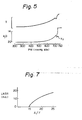
- the base air-fuel ratio A/F in a driving mode for a high altitude location changes as illustrated in Fig. 4, i.e., the base air-fuel ratio A/F changes by two steps, so that the change of the base air-fuel ratio A/F becomes small, as compared with the prior art as illustrated in Fig. 2 in which the base air-fuel ratio A/F changes by a single step, thus reducing the change of torque.
- the base air-fuel ratio A/F changes by two steps, it falls to the lean side as indicated by an arrow X 3 in Fig. 5, thus inviting fluctuation of torque.
- the allowed limit value on the lean side is applied to the second base air-fuel ratio. That is, the second aimed air-fuel ratio is equal to or smaller than the allowed limit value.
- reference numeral 1 designates a four-cycle spark ignition engine disposed in an automotive vehicle.
- a surge tank 3 in which a pressure sensor 4 is provided.
- the pressure sensor 4 is used for detecting the absolute pressure within the intake-air passage 2 and transmits its output signal to a multiplexer-incorporating analog-to-digital (A/D) converter 101 of a control circuit 10.
- A/D analog-to-digital
- a throttle sensor 6 which incorporates two switches. One of the switches is turned on when the opening TA of the throttle valve 5 is larger than a relatively small definite value such as 25°, while the other is turned on when the opening TA of the throttle valve 5 is larger than a relatively large definite value such as 50°.
- the outputs of the throttle sensor 6 are supplied to an input/output (I/O) interface 103 of the control circuit 10.
- crank angle sensors 8 and 9 Disposed in a distributor 7 are crank angle sensors 8 and 9 for detecting the angle of the crankshat (not shown) of the engine 1.
- the crank-angle sensor 8 generates a pulse signal at every 720° crank angle (CA) while the crank-angle sensor 9 generate a pulse signal at every 30°CA.
- the pulse signals of the crank angle sensors 8 and 9 are supplied to the I/O interface 103 of the control circuit 10.
- the pulse signal of the crank angle sensor 9 is then supplied to an interruption terminal of a central processing unit (CPU) 105.
- CPU central processing unit
- a fuel injector 11 for supplying pressurized fuel from the fuel system (not shown) to the air-intake port of the cylinder of the engine 1.
- other fuel injectors are also provided for other cylinders, though not shown in Fig. 6.
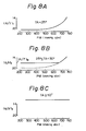
- a lean mixture sensor 13 for detecting the concentration of oxygen composition in the exhaust gas.
- the lean mixture sensor 13 generates a limit current signal LNSR as shown in Fig. 7 and transmits it via a current-to-voltage converter circuit 102 of the control circuit 10 to the A/D converter 101 thereof.
- the control circuit 10 which may be constructed by a microcomputer, includes a driver circuit 104 for driving the fuel injector 11, a timer counter 106, a read-only memory (ROM) 107 for storing a main routine, interrupt routines such as a fuel injection routine, an ignition timing routine, tables (maps), constants, etc., a random access memory 108 (RAM) for storing temporary data, a clock generator 109 for generating various clock signals, and the like, in addition to the A/D converter 101, the current-to-voltage converter circuit 102, the I/O interface 103, and the CPU 105.
- ROM read-only memory
- RAM random access memory
- clock generator 109 for generating various clock signals, and the like, in addition to the A/D converter 101, the current-to-voltage converter circuit 102, the I/O interface 103, and the CPU 105.
- the timer counter 106 may include a free-run counter, a compare register, a comparator for comparing the content of the free-run counter with that of the compare register, flag registers for compare interruption, injection control, and the like.
- the timer counter 106 also may include a plurality of compare registers and a plurality of comparators. In this case, the timer counter 106 is used for controlling the injection start and end operation.
- Interruptions occur at the CPU 105, when the A/D converter 101 completes an A/D conversion and generates an interrupt signal; when the crank angle sensor 9 generates a pulse signal; when the timer counter 106 generates a compare interrupt signal; and when the clock generator 109 generates a special clock signal.
- the pressure data PM of the pressure sensor 4 and the limit current data LNSR of the lean mixture sensor 13 are fetched by an A/D conversion routine executed at every predetermined time period and are then stored in the RAM 108. That is, the data PM and LNSR in the RAM 108 are renewed at every predetermined time period.
- the engine rotational speed Ne is calculated by an interrupt routine executed at 30°CA, i.e. at every pulse signal of the crank angle sensor 9, and is then stored in the RAM 108.
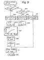
- Figures 8A, 8B, and 8C are graphs of the base air-fuel ratio used in the present invention.
- the opening TA of the throttle valve 5 is smaller than 25°
- feedback of the air-fuel ratio of the engine is carried out so that the air-fuel ratio is brought close to a base air-fuel ratio (A/F) 1 calculated in accordance with the intake air pressure data PM as shown in Fig. 8A.
- PM 760 mmHg abs when TA ⁇ 25°.
- the opening TA of the throttle valve 5 is equal to or larger than 25° and is smaller than 50°
- feedback of the air-fuel ratio of the engine is carried out so that the air-fuel ratio is brought close to a base air-fuel ratio (A/F) 2 calculated in accordance with the intake air pressure data PM as shown in Fig. 8B.
- the base air-fuel ratio (A/F)2 is on the rich side as compared with the base air-fuel ratio (A/F) 1 .
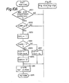
- Figure 9 is a routine for calculating a base air-fuel ratio executed as one part of the main routine, or at a predetermined time period or crank angle.
- one of the outputs of the throttle sensor 6 is fetched from the I/O interface 103, and it is determined whether or not the opening TA of the throttle valve 5 satisfies TA ⁇ 25°.
- the other of the outputs of the throttle sensor 6 is fetched from the I/O interface 103, and it is determined whether or not the opening TA of the throttle valve 5 satisfies TA ⁇ 50°.
- step 902 a base air-fuel ratio (A/F) 1 is calculated from a one-dimensional map stored in the ROM 107 by using the parameter PM as shown in Fig. 8A.
- step 903 A/F ⁇ (A/F) 1 .
- step 905 a base air-fuel ratio (A/F) 2 is calculated from a one-dimensional map stored in the ROM 107 by using the parameter PM as shown in Fig. 8B.
- step 906 A/F ⁇ (A/F) 2 .
- a comparison reference value IR of the limit current LNSR of the lean sensor 13 is calculated from a one-dimensional map by using the parameter A/F, and then at step 908, IR is stored in the RAM 108. Further, at step, a power fuel increment FPOWER is cleared.
- step 910 a power fuel increment FPOWER is calculated from a two-dimensional map stored in the ROM 107 by using the parameters PM and Ne.
- step 911 FPOWER obtained at step 909 or 910 is stored in the RAM 108. This routine is completed by step 912.
- Figure 10 is a routine for calculating an air-fuel ratio feedback correction coefficient FAF executed at every predetermined time period.
- step 1001 it is determined whether or not all the feedback control (closed-loop control) conditions are satisfied.
- the feedback control conditions are as follows:
- step 1002 the output LNSR of the lean mixture sensor 13 stored in the RAM 108 is compared with the comparison reference value IR, thereby determining whether the current air-fuel ratio is on the rich side or on the lean side with respect to the aimed air-fuel ratio. If LNSR ⁇ IR so that the current air-fuel ratio is on the rich side, the control proceeds to step 1003, in which a lean sKip flag CAFL is set, i.e., CAFI. ⁇ "1". Note that the lean skip flag CAFL is used for a skip operation when a first change from the rich side to the lean side occurs in the controlled air-fuel ratio.
- step 1004 it is determined whether or not a rich skip flag CAFR is "1".
- the skip flag CAFR is used for a skip operation when a first change from the lean side to the rich side occurs in the controlled air-fuel ratio.
- the control proceeds to step 1005, which decreases the coefficient FAF by a relatively large amount SKP 1 .
- step 1006 the rich skip flag CAFR is cleared, i.e., CAFR ⁇ "0".
- step 1007 decreases the coefficient FAF by a relatively small amount K 1 .
- SKP 1 is a constant for a skip operation which remarkably decreases the coefficient FAF when a first change from the lean side (LNSR > IR) to the rich side (LNSR ⁇ IR) occurs in the controlled air-fuel ratio
- K 1 is a constant for an integration operation which gradually decreases the coefficient FAF when the controlled air-fuel ratio is on the rich side.
- step 1002 if LNSR > IR so that the current air-fuel ratio is on the lean side, the control proceeds to step 1008 in which the rich skip flag CAFR is set, i.e., CAFR + "I". Then, at step 1009, it is determined whether or not the lean skip flag CAFL is "1". As a result, if the lean skip flag CAFL is "1", the control proceeds to step 1010, which increases the coefficient FAF by a relatively large amount SKP 2 . Then, at step 1011, the lean skip flag CAFL is cleared, i.e., CAFL + "0".
- step 1012 increases the coefficient FAF by a relatively small amount K 2 .
- SKP 2 is a constant for a skip operation which remarkably increases the coefficient FAF when a first change from the rich side (LNSR ⁇ IR) to the lean side (LNSR > IR) occurs in the controlled air-fuel ratio
- K 2 is a constant for an integration operation which gradually increases the coefficient FAF when the controlled air-fuel ratio is on the lean side.
- the air-fuel feedback correction coefficient FAF obtained at steps 1005, 1007, 1010, 1012, or 1013 is stored in the RAM 108, and the routine of Fig. 10 is completed by step 1015.
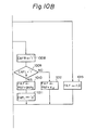
- Figure 11 is a routine for calculating a fuel injection time period TAU executed at every predetermined crank angle.
- this routine is executed at every 360°CA in a simultaneous fuel injection system for simultaneously injecting all the injectors and is executed at every 180°CA in a sequential fuel injection system applied to a four-cylinder engine for sequentially injecting the injectors thereof.
- a base fuel injection time period TAUP is calculated from a two-dimensional map stored in the ROM 107 by using the parameters PM and Ne. Then, at step 1102, a fuel injection time period TAU is calculated by TAU ⁇ TAUP ⁇ FAF-( ⁇ +FPOWER) ⁇ + y where a, ⁇ , and ⁇ are correction factors determined by other parameters such as the signal of the intake air temperature sensor, the voltage of the battery (both not shown), and the like. At step 1103, the calculated fuel injection time period TAU is stored on the RAM 108, and the routine of Fig. 11 is completed by step 1104.
- FIG. 12 Another example of controlling fuel injection amount will be explained with reference to Figs. 12, 13, and 14. Note Figs. 12 and i3 are provided instead of Fig. 9, and Fig. 14 is provided instead of Fig. 11.
- Figure 12 is a routine for calculating a lean air-fuel ratio correction coefficient KLEAN executed at every predetermined time period. Note that the coefficient KLEAN satisfies the condition: KhEAN ⁇ 1.0.
- KLEANPM is calculated from a one-dimensional map stored in the ROM 107 by using the parameter PM as shown in the block of step 1202.
- KLEANNE is calculated from a one-dimensional map stored in the ROM 107 by using the parameter Ne as shown on the block of step 1203. Then at step 1204,
- step 1209 KLEAN is stored in the RAM 108, and this routine of fig. 12 is completed by step 1210.
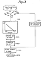
- Figure 13 is a routine for clculating a comparison reference value IR executed at every predetermined time period.
- step 1305 FPOWER obtained at step 1304 or 1305 is stored in the RAM 108. This routine is completed by step 1306.
- step 1102' is provided instead of step 1102 of Fig. 11.
- a fuel injection time period TAU is calculated by TAU ⁇ TAUP ⁇ FAF ⁇ ( ⁇ +RLEAN+FPOWER) ⁇ + ⁇ .
- Figure 15 is a routine for controlling the fuel injection in accordance with the fuel injection time period TAU calculated by the routine of Fig. 11 or 14, executed at every predetermined crank angle. Also, this routine is executed at every 360°CA in a simultaneous fuel injection system and is executed at every 180 0 CA in an sequential fuel injection system applied to a four-cylinder engine.
- step 1501 the fuel injection time period TAU stored in the RAM 108 is read out and is transmitted to the D register (not shown) included in the CPU 105.
- step 1502 an invalid fuel injection time period TAUV which is also stored in the RAM 108 is added to the content of the D register.
- step 1503 the current time CNT of the free-run counter of the timer counter 106 is read out and is 'added to the content of the D register, thereby obtaining an injection end time t in the D register. Therefore, at step 1504, the content of the D register is stored as the injection end time t in the RAM 108.
- step 1505 the current time CNT of the free-run counter is read out and is set in the D register. Then, at step 1506, a small time period t 0 , which is definite or determined by the predetermined parameters, is added to the content of the D register. At step 1507, the content of the D register is set in the compare register of the timer counter 106, and at step 1508, a fuel injection execution flag and a compare interrupt permission flag are set in the registers of the timer counter 106. The routine of Fig. 15 is completed by step 1509.
- an injection-on. signal due to the presence of the fuel injection execution flag is transmitted from the time counter 6 via the I/O interface 103 to the driver circuit 104, thereby initiating fuel injection by the fuel injector 11.
- a compare interrupt signal due to the presence of the compare interrupt permission flag is transmitted from the timer counter 106 to the CPU 105, thereby initiating a compare interrupt routine as illustrated in Fig. 16.
- step 1601 the injection end time t stored in the RAM 108 is read out and is transmitted to the D register. Then, at step 1602, the content of the D register, i.e., the injection end time t , is set in the compare register of the timer counter, and at step 1603, the fuel injection execution flag and the compare interrupt permission flag are reset.
- the routine of Fig. 16 is completed by step 1604.
- the present invention can be also applied to a fuel injection system using the other parameters such as the intake air amount and the engine speed or the throttle opening value and the engine speed.
Applications Claiming Priority (2)
| Application Number | Priority Date | Filing Date | Title |
|---|---|---|---|
| JP59089240A JPS60233332A (ja) | 1984-05-07 | 1984-05-07 | 内燃機関の空燃比制御装置 |
| JP89240/84 | 1984-05-07 |
Publications (3)
| Publication Number | Publication Date |
|---|---|
| EP0162365A2 true EP0162365A2 (de) | 1985-11-27 |
| EP0162365A3 EP0162365A3 (en) | 1986-12-10 |
| EP0162365B1 EP0162365B1 (de) | 1990-04-11 |
Family
ID=13965217
Family Applications (1)
| Application Number | Title | Priority Date | Filing Date |
|---|---|---|---|
| EP85105502A Expired EP0162365B1 (de) | 1984-05-07 | 1985-05-06 | Verfahren und Gerät zur Steuerung des Luft-Kraftstoffverhältnisses in einer Innenbrennkraftmaschine |
Country Status (4)
| Country | Link |
|---|---|
| US (1) | US4719888A (de) |
| EP (1) | EP0162365B1 (de) |
| JP (1) | JPS60233332A (de) |
| DE (1) | DE3577119D1 (de) |
Cited By (1)
| Publication number | Priority date | Publication date | Assignee | Title |
|---|---|---|---|---|
| DE102005056947A1 (de) * | 2005-07-21 | 2007-02-01 | Sin Etke Technology Co., Ltd. | Fahrzeugsicherheitssystem |
Families Citing this family (14)
| Publication number | Priority date | Publication date | Assignee | Title |
|---|---|---|---|---|
| JPH0713492B2 (ja) * | 1987-05-28 | 1995-02-15 | 株式会社ユニシアジェックス | 電子制御燃料噴射式内燃機関の空燃比制御装置 |
| EP0308870B1 (de) * | 1987-09-22 | 1992-05-06 | Japan Electronic Control Systems Co., Ltd. | Elektronische Steuerungsvorrichtung für das Kraftstoff-Luftverhältnis eines inneren Verbrennungsmotors |
| EP0369470B1 (de) * | 1988-11-17 | 1993-02-24 | Nec Corporation | Datenverarbeitungseinrichtung zur Erzeugung einer Folge von Impulsen die eine variable Länge an den Ausgängen aufweisen |
| US5067465A (en) * | 1990-02-15 | 1991-11-26 | Fujitsu Ten Limited | Lean burn internal combustion engine |
| US5190008A (en) * | 1990-02-15 | 1993-03-02 | Fujitsu Ten Limited | Lean burn internal combustion engine |
| JP2678985B2 (ja) * | 1991-09-18 | 1997-11-19 | 本田技研工業株式会社 | 内燃エンジンの空燃比制御装置 |
| US5443594A (en) * | 1992-05-27 | 1995-08-22 | Toyota Jidosha Kabushiki Kaisha | Air-fuel ratio control apparatus of vehicle equipped with automatic transmission |
| US5261382A (en) * | 1992-09-22 | 1993-11-16 | Coltec Industries Inc. | Fuel injection system |
| US5546919A (en) * | 1993-08-31 | 1996-08-20 | Yamaha Hatsudoki Kabushiki Kaisha | Operating arrangement for gaseous fueled engine |
| US5575266A (en) * | 1993-08-31 | 1996-11-19 | Yamaha Hatsudoki Kabushiki Kaisha | Method of operating gaseous fueled engine |
| DE19612453C2 (de) * | 1996-03-28 | 1999-11-04 | Siemens Ag | Verfahren zum Bestimmen der in das Saugrohr oder in den Zylinder einer Brennkraftmaschine einzubringenden Kraftstoffmasse |
| KR100580501B1 (ko) | 2004-05-31 | 2006-05-15 | 현대자동차주식회사 | 린번 조건의 개선을 통한 차량의 연비 및 주행성능 향상방법 |
| US7355292B2 (en) * | 2005-06-02 | 2008-04-08 | Denso Corporation | Power generation control apparatus for internal combustion engine |
| US11181052B2 (en) * | 2019-09-26 | 2021-11-23 | Setaysha Technical Solutions, Llc | Air-fuel metering for internal combustion reciprocating engines |
Citations (4)
| Publication number | Priority date | Publication date | Assignee | Title |
|---|---|---|---|---|
| US3973529A (en) * | 1973-07-03 | 1976-08-10 | Robert Bosch G.M.B.H. | Reducing noxious components from the exhaust gases of internal combustion engines |
| US4088095A (en) * | 1975-05-20 | 1978-05-09 | Nissan Motor Company, Limited | Closed-loop mixture control system for an internal combustion engine using a differential amplifier with a reference voltage variable according to engine operating parameters |
| DE3231122A1 (de) * | 1982-08-21 | 1984-02-23 | Robert Bosch Gmbh, 7000 Stuttgart | Regeleinrichtung fuer die gemischzusammensetzung einer brennkraftmaschine |
| EP0136519A2 (de) * | 1983-08-24 | 1985-04-10 | Hitachi, Ltd. | Luft/Kraftstoffverhältnissteuereinrichtung für Innenbrennkraftmaschinen |
Family Cites Families (2)
| Publication number | Priority date | Publication date | Assignee | Title |
|---|---|---|---|---|
| JPS5623551A (en) * | 1979-08-02 | 1981-03-05 | Fuji Heavy Ind Ltd | Air-fuel ratio controller |
| JPS5865946A (ja) * | 1981-10-14 | 1983-04-19 | Toyota Motor Corp | 内燃機関の吸気装置 |
-
1984
- 1984-05-07 JP JP59089240A patent/JPS60233332A/ja active Granted
-
1985
- 1985-05-06 DE DE8585105502T patent/DE3577119D1/de not_active Expired - Lifetime
- 1985-05-06 EP EP85105502A patent/EP0162365B1/de not_active Expired
- 1985-05-07 US US06/731,524 patent/US4719888A/en not_active Expired - Fee Related
Patent Citations (4)
| Publication number | Priority date | Publication date | Assignee | Title |
|---|---|---|---|---|
| US3973529A (en) * | 1973-07-03 | 1976-08-10 | Robert Bosch G.M.B.H. | Reducing noxious components from the exhaust gases of internal combustion engines |
| US4088095A (en) * | 1975-05-20 | 1978-05-09 | Nissan Motor Company, Limited | Closed-loop mixture control system for an internal combustion engine using a differential amplifier with a reference voltage variable according to engine operating parameters |
| DE3231122A1 (de) * | 1982-08-21 | 1984-02-23 | Robert Bosch Gmbh, 7000 Stuttgart | Regeleinrichtung fuer die gemischzusammensetzung einer brennkraftmaschine |
| EP0136519A2 (de) * | 1983-08-24 | 1985-04-10 | Hitachi, Ltd. | Luft/Kraftstoffverhältnissteuereinrichtung für Innenbrennkraftmaschinen |
Cited By (2)
| Publication number | Priority date | Publication date | Assignee | Title |
|---|---|---|---|---|
| DE102005056947A1 (de) * | 2005-07-21 | 2007-02-01 | Sin Etke Technology Co., Ltd. | Fahrzeugsicherheitssystem |
| DE102005056947B4 (de) * | 2005-07-21 | 2008-05-29 | Sin Etke Technology Co., Ltd. | Fahrzeugsicherheitssystem |
Also Published As
| Publication number | Publication date |
|---|---|
| US4719888A (en) | 1988-01-19 |
| JPS60233332A (ja) | 1985-11-20 |
| JPH0531643B2 (de) | 1993-05-13 |
| EP0162365A3 (en) | 1986-12-10 |
| EP0162365B1 (de) | 1990-04-11 |
| DE3577119D1 (de) | 1990-05-17 |
Similar Documents
| Publication | Publication Date | Title |
|---|---|---|
| US4964272A (en) | Air-fuel ratio feedback control system including at least downstreamside air-fuel ratio sensor | |
| US5278762A (en) | Engine control apparatus using exhaust gas temperature to control fuel mixture and spark timing | |
| US4508075A (en) | Method and apparatus for controlling internal combustion engines | |
| US4475517A (en) | Air-fuel ratio control method and apparatus for an internal combustion engine | |
| US5711272A (en) | Fuel property detection for an engine using engine speed | |
| US4644921A (en) | Method and apparatus for controlling air-fuel ratio in internal combustion engine | |
| US4467770A (en) | Method and apparatus for controlling the air-fuel ratio in an internal combustion engine | |
| US4719888A (en) | Method and apparatus for controlling air-fuel ratio in internal combustion engine | |
| US4627402A (en) | Method and apparatus for controlling air-fuel ratio in internal combustion engine | |
| US4469072A (en) | Method and apparatus for controlling the fuel-feeding rate of an internal combustion engine | |
| US4457282A (en) | Electronic control for fuel injection | |
| US4651700A (en) | Method and apparatus for controlling air-fuel ration in internal combustion engine | |
| US4667631A (en) | Method and apparatus for controlling air-fuel ratio in internal combustion engine | |
| US4648370A (en) | Method and apparatus for controlling air-fuel ratio in internal combustion engine | |
| US4854124A (en) | Double air-fuel ratio sensor system having divided-skip function | |
| KR0122459B1 (ko) | 다기통 엔진의 공연비 제어장치 | |
| EP0160949A2 (de) | Verfahren und Gerät zur Steuerung des Luft-Kraftstoffverhältnisses in einer Innenbrennkraftmaschine mit sequentieller Kraftstoffeinspritzung | |
| US4653451A (en) | Method and apparatus for detecting surging in internal combustion engine | |
| US4713766A (en) | Method and apparatus for controlling air-fuel ratio in internal combustion engine | |
| US4502448A (en) | Method for controlling control systems for internal combustion engines immediately after termination of fuel cut | |
| JPS59548A (ja) | 内燃エンジンの燃料供給装置の制御方法 | |
| JPS61135950A (ja) | 電子制御エンジンの空燃比フイ−ドバツク制御方法 | |
| JP2609126B2 (ja) | 内燃機関の空燃比フィードバック制御装置 | |
| JPS6035153A (ja) | 内燃機関の燃料噴射制御方法 | |
| JPS60209644A (ja) | 内燃機関の燃料噴射制御装置 |
Legal Events
| Date | Code | Title | Description |
|---|---|---|---|
| PUAI | Public reference made under article 153(3) epc to a published international application that has entered the european phase |
Free format text: ORIGINAL CODE: 0009012 |
|
| 17P | Request for examination filed |
Effective date: 19850506 |
|
| AK | Designated contracting states |
Designated state(s): DE FR GB |
|
| PUAL | Search report despatched |
Free format text: ORIGINAL CODE: 0009013 |
|
| AK | Designated contracting states |
Kind code of ref document: A3 Designated state(s): DE FR GB |
|
| 17Q | First examination report despatched |
Effective date: 19871116 |
|
| GRAA | (expected) grant |
Free format text: ORIGINAL CODE: 0009210 |
|
| AK | Designated contracting states |
Kind code of ref document: B1 Designated state(s): DE FR GB |
|
| REF | Corresponds to: |
Ref document number: 3577119 Country of ref document: DE Date of ref document: 19900517 |
|
| ET | Fr: translation filed | ||
| PLBE | No opposition filed within time limit |
Free format text: ORIGINAL CODE: 0009261 |
|
| STAA | Information on the status of an ep patent application or granted ep patent |
Free format text: STATUS: NO OPPOSITION FILED WITHIN TIME LIMIT |
|
| 26N | No opposition filed | ||
| PGFP | Annual fee paid to national office [announced via postgrant information from national office to epo] |
Ref country code: GB Payment date: 19930423 Year of fee payment: 9 |
|
| PGFP | Annual fee paid to national office [announced via postgrant information from national office to epo] |
Ref country code: FR Payment date: 19930510 Year of fee payment: 9 |
|
| PGFP | Annual fee paid to national office [announced via postgrant information from national office to epo] |
Ref country code: DE Payment date: 19930524 Year of fee payment: 9 |
|
| PG25 | Lapsed in a contracting state [announced via postgrant information from national office to epo] |
Ref country code: GB Effective date: 19940506 |
|
| GBPC | Gb: european patent ceased through non-payment of renewal fee |
Effective date: 19940506 |
|
| PG25 | Lapsed in a contracting state [announced via postgrant information from national office to epo] |
Ref country code: FR Effective date: 19950131 |
|
| PG25 | Lapsed in a contracting state [announced via postgrant information from national office to epo] |
Ref country code: DE Effective date: 19950201 |
|
| REG | Reference to a national code |
Ref country code: FR Ref legal event code: ST |