EP0162355A2 - Motorlager, insbesondere Hydrolager - Google Patents
Motorlager, insbesondere Hydrolager Download PDFInfo
- Publication number
- EP0162355A2 EP0162355A2 EP85105394A EP85105394A EP0162355A2 EP 0162355 A2 EP0162355 A2 EP 0162355A2 EP 85105394 A EP85105394 A EP 85105394A EP 85105394 A EP85105394 A EP 85105394A EP 0162355 A2 EP0162355 A2 EP 0162355A2
- Authority
- EP
- European Patent Office
- Prior art keywords
- engine
- thermal
- mounting
- bearing according
- engine mount
- Prior art date
- Legal status (The legal status is an assumption and is not a legal conclusion. Google has not performed a legal analysis and makes no representation as to the accuracy of the status listed.)
- Granted
Links
Images
Classifications
-
- B—PERFORMING OPERATIONS; TRANSPORTING
- B60—VEHICLES IN GENERAL
- B60K—ARRANGEMENT OR MOUNTING OF PROPULSION UNITS OR OF TRANSMISSIONS IN VEHICLES; ARRANGEMENT OR MOUNTING OF PLURAL DIVERSE PRIME-MOVERS IN VEHICLES; AUXILIARY DRIVES FOR VEHICLES; INSTRUMENTATION OR DASHBOARDS FOR VEHICLES; ARRANGEMENTS IN CONNECTION WITH COOLING, AIR INTAKE, GAS EXHAUST OR FUEL SUPPLY OF PROPULSION UNITS IN VEHICLES
- B60K5/00—Arrangement or mounting of internal-combustion or jet-propulsion units
- B60K5/12—Arrangement of engine supports
- B60K5/1208—Resilient supports
- B60K5/1233—Resilient supports comprising protective elements, e.g. for protecting against heat, dust
-
- F—MECHANICAL ENGINEERING; LIGHTING; HEATING; WEAPONS; BLASTING
- F16—ENGINEERING ELEMENTS AND UNITS; GENERAL MEASURES FOR PRODUCING AND MAINTAINING EFFECTIVE FUNCTIONING OF MACHINES OR INSTALLATIONS; THERMAL INSULATION IN GENERAL
- F16F—SPRINGS; SHOCK-ABSORBERS; MEANS FOR DAMPING VIBRATION
- F16F13/00—Units comprising springs of the non-fluid type as well as vibration-dampers, shock-absorbers, or fluid springs
- F16F13/04—Units comprising springs of the non-fluid type as well as vibration-dampers, shock-absorbers, or fluid springs comprising both a plastics spring and a damper, e.g. a friction damper
- F16F13/06—Units comprising springs of the non-fluid type as well as vibration-dampers, shock-absorbers, or fluid springs comprising both a plastics spring and a damper, e.g. a friction damper the damper being a fluid damper, e.g. the plastics spring not forming a part of the wall of the fluid chamber of the damper
Definitions
- the invention relates to an engine mount, in particular a hydraulic mount, mounted between an engine support part and a body of a motor vehicle.
- Engine mounts are currently operated in a temperature range of around 160 ° C.
- the upper temperature limit essentially depends on the operating temperature of the associated engine, while the lower one is given by the ambient temperature.
- the dynamic behavior of the engine mounts also becomes a function of temperature. This applies in particular to hydraulic bearings, in which the damping and dynamic stiffness are essentially determined by the properties of the damper fluid used, and here in particular by the viscosity of the damper fluid, which in turn shows a strong temperature dependence.
- the aim is to use comparatively temperature-stable suspension spring materials and damper fluids.
- radiation shields arranged on the motor side are used as protection against the radiant heat of the motor.
- the invention is therefore based on the object of creating an engine mount of the type specified, in which a low temperature load and thus a higher temperature stability is achieved.
- the procedure is carried out under two different aspects, namely that the amount of heat influencing the engine mount is first reduced by a thermal insulation layer on the engine side, which can also serve as train protection.
- the heat transfer between the engine support part, generally the engine support arm, and the body is improved, while at the same time ensuring that the acoustic properties of the bearing do not deteriorate.
- the engine mount is bridged by non-load-bearing thermal bridges made of materials with high thermal conductivity.
- thermal bridges are either directly connected to the motor-side part of the motor mount, for example an additionally used radiation shield, or the motor support arm.
- thermal bridges are also provided between the hydraulic bearing body and the body.
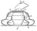
- the hydraulic bearing shown in the figure, generally indicated by reference numeral 10, is located between a body 12 and an engine support arm 14 of a motor vehicle.
- the hydraulic bearing 10 On the side facing the motor support arm 14, the hydraulic bearing 10 is provided with a heat insulation layer 16, which consists of a ceramic material or a heat-insulating plastic.
- a radiation shield 22 as protection against the radiation heat of the - (not shown) attached to the motor vehicle engine; the radiation shield 22 is in turn connected to the motor support arm 14.
- the thermal bearings 18, 20 surrounding the hydraulic bearing 10 are provided.
- thermal bridges 18, 20 are non-load-bearing with a curved cross-sectional shape between the body on the one hand and the hydraulic bearing 10 or the radiation shield 22 on the other hand and consist of materials with high thermal conductivity, in particular metals. Good results are achieved with thermal bridges 18, 20 made of copper, steel or brass, it being possible to use the corresponding materials in strip form with vanishing flexural rigidity.
- the thermal bridge 20 transfers the heat transferred to the hydraulic bearing 10 or the heat generated in the hydraulic bearing 10 to the body 12, the thermal bridge E 18 conducts the heat of the radiation shield 22, resulting in an overall reduction in the operating temperature of the hydraulic bearing 10.
Abstract
Description
- Die Erfindung betrifft ein zwischen einem Motortragteil und einer Karosserie eines Kraftfahrzeugs angebrachtes Motorlager, insbesondere Hydrolager.
- Motorlager werden zur Zeit in einem Temperaturbereich von etwa 160°C betrieben. Die obere erreichte Temperaturgrenze hängt im wesentlichen von der Betriebstemperatur des zugehörigen Motors ab, während die untere durch die Umgebungstemperatur gegeben ist.
- Über die Temperaturabhängigkeit der Stoffeigenschaften der Materialien, die in Motorlagern eingesetzt werden, wird auch das dynamische Verhalten des Motorlagers eine Funktion der Temperatur. Dies gilt insbesondere für Hydrolager, bei denen die Dämpfung und die dynamische Steifigkeit im wesentlichen durch die Eigenschaften der eingesetzten Dämpferflüssigkeit, und hier wiederum insbesondere durch die Viskosität der Dämpferflüssigkeit, bestimmt werden, die wiederum eine starke Temperaturabhängigkeit zeigt.
- Zur Stabilisierung des thermischen Verhaltens von Motorlagern wird deshalb angestrebt, vergleichsweise temperaturstabile Tragfederwerkstoffe und Dämpferflüssigkeiten zu verwenden. Außerdem werden als Schutz gegen die Strahlungswärme des Motors motorseitig angeordnete Strahlungsschilder verwendet.
- Diese Maßnahmen führen jedoch nur zu einer vergleichsweise geringen Reduktion der thermischen Belastung von Motorlagern.
- Der Erfindung liegt deshalb die Aufgabe zugrunde, ein Motorlager der angegebenen Gattung zu schaffen, bei dem eine geringe Temperaturbelastung und damit eine höhere Temperaturstabilität erreicht wird.
- Insbesondere soll ein Motorlager vorgeschlagen werden, dessen thermische Belastung wesentlich reduziert ist.
- Dies wird erfindungsgemäß durch die im kennzeichnenden Teil des Anspruchs 1 angegebenen Merkmale erreicht.
- Zweckmäßige Ausführungsformen sind in den Unteransprüchen zusammengestellt.
- Die mit der Erfindung erzielten Vorteile beruhen insbesondere darauf, daß durch die angegebenen Maßnahmen die thermische Belastung des Motorlagers verringert und damit seine Temperaturstabilität verbessert wird. Dies wird mit vergleichsweise einfachen Maßnahmen erreicht, die ohne weiteres bei den handelsüblichen Kraftfahrzeugen eingesetzt werden könne, da im Bereich der Motorlager ausreichend Platz für die Unterbringung der noch zu erörternden Wärmeschutzmaßnahmen zur Verfügung steht.
- Dabei wird unter zwei unterschiedlichen Aspekten vorgegangen, und zwar wird zunächst die das Motorlager beeinflussende Wärmemenge durch eine motorseitige Wärmedämmschicht verringert, die gleichzeitig auch als Zugsicherung dienen kann.
- Außerdem wird der Wärmeübergang zwischen dem Motortragteil, im allgemeinen dem Motortragarm, und der Karosserie verbessert, wobei gleichzeitig gewährleistet wird, daB sich die akustische Eigenschaften des Lagers nicht verschlechtern. Zu diesem Zweck wird das Motorlager durch nicht-tragende, aus Materialien mit hoher Wärmeleitfähigkeit bestehende Wärmebrücken überbrückt.
- Diese Wärmebrücken sind entweder an den motorseitigen Teil des Motorlagers, beispielsweise einem zusätzlich verwendeten Strahlungsschild bzw. den Motortragarm direkt angeschlossen.
- Zur Verbesserung des Transports der im Lager dissipierten Dämpfungsarbeit und der vom Motor an das Lager übertragenen Restwärme an die Karosserie sind außerdem Wärmebrücken zwischen dem Hydrolagerkörper und der Karosserie vorgesehen.
- Die Erfindung wird im folgenden anhand eines Ausführungbeispiels unter Bezugnahme auf die beiliegende, schematische Zeichnung näher erläutert, deren einzige Figur einen Schnitt durch ein Motorlager im eingebauten Zustand zeigt.
- Das aus der Figur ersichtliche, allgemein durch das Bezugszeichen 10 angedeutete Hydrolager befindet sich zwischen einer Karosserie 12 und einem Motortragarm 14 eines Kraftfahrzeugs. Auf der dem Motortragarm 14 zugewandten Seite ist das Hydrolager 10 mit einer Wärmedämmschicht 16 versehen, die aus einem keramischen Werkstoff oder einem wärmeisolierenden Kunststoff besteht.
- Auf dieser Wärmedämmschicht 16 ist ein Strahlungsschild 22 als Schutz gegen die Strahlungswärme des-Kraftfahrzeugmotors (nicht dargestellt) befestigt; der Strahlungsschild 22 ist wiederum mit dem Motortragarm 14 verbunden. Zur Verbesserung des Wärmeübergangs zwischen dem Motortragarm 14 und der Karosserie 12 bzw. dem Hydrolagerkörper 10 und der Karosserie und zwar ohne Verschlechterung der akustischen Eigenschaften, sind das Hydrolager 10 umgebende Wärmebrücken 18, 20 vorgesehen.
- Diese Wärmebrücken 18, 20 sind nicht-tragende mit gewölbter Querschnittsform zwischen der Karosserie einerseits und dem Hydrolager 10 bzw. dem Strahlungsschild 22 andererseits angeordnet und bestehen aus Werkstoffen mit hoher Wärmeleitfähigkeit, insbesondere Metallen. Gute Ergebnisse werden mit Wärmebrücken 18, 20 aus Kupfer, Stahl oder Messing erreicht, wobei die entsprechenden Werkstoffe in Bandform mit verschwindender Biegesteifigkeit verwendet werden können.
- Während die Wärmebrücke 20 die auf das Hydrolager 10 übertragene oder die im Hydrolager 10 entstehende Wärmε zur Karosserie 12 hin ableitet, leitet die WärmebrückE 18 die Wärme des Strahlungsschildes 22 weiter, wodurch sich insgesamt eine Verringerung der Betriebstemperatu: des Hydrolagers 10 ergibt.
Claims (6)
Applications Claiming Priority (2)
| Application Number | Priority Date | Filing Date | Title |
|---|---|---|---|
| DE3419060A DE3419060C1 (de) | 1984-05-22 | 1984-05-22 | Motorlager,insbesondere Hydrolager |
| DE3419060 | 1984-05-22 |
Publications (3)
| Publication Number | Publication Date |
|---|---|
| EP0162355A2 true EP0162355A2 (de) | 1985-11-27 |
| EP0162355A3 EP0162355A3 (en) | 1987-01-07 |
| EP0162355B1 EP0162355B1 (de) | 1989-08-16 |
Family
ID=6236566
Family Applications (1)
| Application Number | Title | Priority Date | Filing Date |
|---|---|---|---|
| EP85105394A Expired EP0162355B1 (de) | 1984-05-22 | 1985-05-03 | Motorlager, insbesondere Hydrolager |
Country Status (3)
| Country | Link |
|---|---|
| EP (1) | EP0162355B1 (de) |
| DE (2) | DE3419060C1 (de) |
| ES (1) | ES286901Y (de) |
Cited By (1)
| Publication number | Priority date | Publication date | Assignee | Title |
|---|---|---|---|---|
| EP1300265A1 (de) * | 1997-04-14 | 2003-04-09 | Nissan Motor Company, Limited | Hinterradaufhängungsvorrichtung |
Families Citing this family (2)
| Publication number | Priority date | Publication date | Assignee | Title |
|---|---|---|---|---|
| FR2730788B1 (fr) * | 1995-02-22 | 1997-06-06 | Hutchinson | Ecran thermique pour biellette de reprise de couple de moteur a combustion interne |
| DE102008039592A1 (de) | 2008-08-25 | 2009-05-07 | Daimler Ag | Motorträger für eine Motorlagerung |
Citations (4)
| Publication number | Priority date | Publication date | Assignee | Title |
|---|---|---|---|---|
| DE2328647A1 (de) * | 1973-06-06 | 1975-01-02 | Daimler Benz Ag | Gummimetallager |
| JPS5849516A (ja) * | 1981-09-16 | 1983-03-23 | Toyota Motor Corp | エンジン支持装置 |
| JPS58105825A (ja) * | 1981-12-18 | 1983-06-23 | Nissan Motor Co Ltd | リアエンジンマウント部構造 |
| DE3214997A1 (de) * | 1982-04-22 | 1983-11-03 | Audi Nsu Auto Union Ag | Lager |
-
1984
- 1984-05-22 DE DE3419060A patent/DE3419060C1/de not_active Expired
-
1985
- 1985-05-03 DE DE8585105394T patent/DE3572389D1/de not_active Expired
- 1985-05-03 EP EP85105394A patent/EP0162355B1/de not_active Expired
- 1985-05-21 ES ES1985286901U patent/ES286901Y/es not_active Expired
Patent Citations (4)
| Publication number | Priority date | Publication date | Assignee | Title |
|---|---|---|---|---|
| DE2328647A1 (de) * | 1973-06-06 | 1975-01-02 | Daimler Benz Ag | Gummimetallager |
| JPS5849516A (ja) * | 1981-09-16 | 1983-03-23 | Toyota Motor Corp | エンジン支持装置 |
| JPS58105825A (ja) * | 1981-12-18 | 1983-06-23 | Nissan Motor Co Ltd | リアエンジンマウント部構造 |
| DE3214997A1 (de) * | 1982-04-22 | 1983-11-03 | Audi Nsu Auto Union Ag | Lager |
Non-Patent Citations (2)
| Title |
|---|
| PATENT ABSTRACTS OF JAPAN, Band 7, Nr. 133 (M-221)[1278], 10. Juni 1983; & JP - A - 58 49516 (TOYOTA JIDOSHA KOGYO K.K.) 23.03.1983 * |
| PATENT ABSTRACTS OF JAPAN, Band 7, Nr. 207 (M-242)[1352], 13. September 1983; & JP - A - 58 105 825 (NISSAN JIDOSHA K.K.) 23.06.1983 * |
Cited By (1)
| Publication number | Priority date | Publication date | Assignee | Title |
|---|---|---|---|---|
| EP1300265A1 (de) * | 1997-04-14 | 2003-04-09 | Nissan Motor Company, Limited | Hinterradaufhängungsvorrichtung |
Also Published As
| Publication number | Publication date |
|---|---|
| EP0162355A3 (en) | 1987-01-07 |
| DE3572389D1 (en) | 1989-09-21 |
| ES286901U (es) | 1985-11-16 |
| ES286901Y (es) | 1986-06-01 |
| EP0162355B1 (de) | 1989-08-16 |
| DE3419060C1 (de) | 1985-10-10 |
Similar Documents
| Publication | Publication Date | Title |
|---|---|---|
| DE19922800B4 (de) | Hilfsrahmen für ein Kraftfahrzeug | |
| EP0897489B1 (de) | Luftfeder | |
| DE60209995T2 (de) | Temperaturkompensierender Flussring | |
| DE3003449A1 (de) | Drucksensor | |
| DE2824250C2 (de) | Trägerelektrode eines Halbleiterbauelements | |
| DE2922437A1 (de) | Zweirohrschwingungsdaempfer mit universell anwendbarer kolbenstangenfuehrung | |
| DE102016203497A1 (de) | Heizeinrichtung für einen Kfz-Betriebsflüssigkeitstank mit einem PTC-Kunststoffkörper | |
| EP0849491B1 (de) | Pendelstütze | |
| EP0461459B1 (de) | Druckmessumformer mit einem rotationssymmetrischen Drucksensor aus Keramik | |
| DE3419060C1 (de) | Motorlager,insbesondere Hydrolager | |
| DE4118490C1 (en) | Mounting support for IC engine - has ceramic thermal insulation between engine support and flexible mounting bearing | |
| DE19617839C2 (de) | Aktives Zweikammer-Motorlager | |
| DE2636507A1 (de) | Mehrschichtiges lagerungs-, stuetz- und dichtungselement | |
| DE2632977A1 (de) | Kuehlvorrichtung zur absenkung der oeltemperatur von oelgeschmierten daempfungslagern | |
| DE1911500A1 (de) | Druckgeschmierte Lager | |
| DE2818564A1 (de) | Verfahren zum korrosionsschutz von aluminiumrohren fuer waermetauscher und entsprechend hergestellter waermetauscher | |
| EP1908987A2 (de) | Elastische Lagerbuchse mit hydraulischer Dämpfung | |
| DD219410A1 (de) | Verfahren zur verbesserung der eigenschaften von fuegeverbindungen | |
| DE102018202353A1 (de) | Vorprodukt mit einem lasttragenden Bauteil sowie Verfahren zur Anpassung besagten lasttragenden Bauteils an eine Lastanforderung | |
| EP0818269A1 (de) | Fahrwerksanordnung | |
| DE102018101100A1 (de) | Verbundbremsscheibe | |
| DE102017222128A1 (de) | Luftfeder | |
| WO1994011249A1 (de) | Hohlleiterabsorber | |
| EP1064661A1 (de) | Aluminium-elektrolytkondensator | |
| DE2903616A1 (de) | Arbeitskolben mit inneren und/oder aeusseren fuehrungsflaechen, insbesondere fuer hydraulische hilfskraftlenkungen von kraftfahrzeugen |
Legal Events
| Date | Code | Title | Description |
|---|---|---|---|
| PUAI | Public reference made under article 153(3) epc to a published international application that has entered the european phase |
Free format text: ORIGINAL CODE: 0009012 |
|
| 17P | Request for examination filed |
Effective date: 19850503 |
|
| AK | Designated contracting states |
Designated state(s): DE FR GB IT SE |
|
| RIN1 | Information on inventor provided before grant (corrected) |
Inventor name: SCIORTINO, GIACOMO Inventor name: ANDRAE, RAINER, DR. |
|
| PUAL | Search report despatched |
Free format text: ORIGINAL CODE: 0009013 |
|
| AK | Designated contracting states |
Kind code of ref document: A3 Designated state(s): DE FR GB IT SE |
|
| RAP1 | Party data changed (applicant data changed or rights of an application transferred) |
Owner name: SCIORTINO, GIACOMO |
|
| 17Q | First examination report despatched |
Effective date: 19880620 |
|
| ITF | It: translation for a ep patent filed |
Owner name: BARZANO' E ZANARDO ROMA S.P.A. |
|
| GRAA | (expected) grant |
Free format text: ORIGINAL CODE: 0009210 |
|
| AK | Designated contracting states |
Kind code of ref document: B1 Designated state(s): DE FR GB IT SE |
|
| GBT | Gb: translation of ep patent filed (gb section 77(6)(a)/1977) | ||
| REF | Corresponds to: |
Ref document number: 3572389 Country of ref document: DE Date of ref document: 19890921 |
|
| ET | Fr: translation filed | ||
| PLBE | No opposition filed within time limit |
Free format text: ORIGINAL CODE: 0009261 |
|
| STAA | Information on the status of an ep patent application or granted ep patent |
Free format text: STATUS: NO OPPOSITION FILED WITHIN TIME LIMIT |
|
| 26N | No opposition filed | ||
| ITTA | It: last paid annual fee | ||
| EAL | Se: european patent in force in sweden |
Ref document number: 85105394.2 |
|
| PGFP | Annual fee paid to national office [announced via postgrant information from national office to epo] |
Ref country code: DE Payment date: 19950419 Year of fee payment: 11 |
|
| PGFP | Annual fee paid to national office [announced via postgrant information from national office to epo] |
Ref country code: SE Payment date: 19950420 Year of fee payment: 11 |
|
| PGFP | Annual fee paid to national office [announced via postgrant information from national office to epo] |
Ref country code: GB Payment date: 19950503 Year of fee payment: 11 |
|
| PGFP | Annual fee paid to national office [announced via postgrant information from national office to epo] |
Ref country code: FR Payment date: 19950511 Year of fee payment: 11 |
|
| PG25 | Lapsed in a contracting state [announced via postgrant information from national office to epo] |
Ref country code: DE Effective date: 19951129 |
|
| PG25 | Lapsed in a contracting state [announced via postgrant information from national office to epo] |
Ref country code: GB Effective date: 19960503 |
|
| PG25 | Lapsed in a contracting state [announced via postgrant information from national office to epo] |
Ref country code: SE Effective date: 19960504 |
|
| GBPC | Gb: european patent ceased through non-payment of renewal fee |
Effective date: 19960503 |
|
| PG25 | Lapsed in a contracting state [announced via postgrant information from national office to epo] |
Ref country code: FR Effective date: 19970131 |
|
| EUG | Se: european patent has lapsed |
Ref document number: 85105394.2 |
|
| REG | Reference to a national code |
Ref country code: FR Ref legal event code: ST |