EP0162046B1 - Dispositif de fermeture de buses muni d'un moyen d'accrochage de buses pour rampe de pulverisation ou d'epandage - Google Patents
Dispositif de fermeture de buses muni d'un moyen d'accrochage de buses pour rampe de pulverisation ou d'epandage Download PDFInfo
- Publication number
- EP0162046B1 EP0162046B1 EP84900508A EP84900508A EP0162046B1 EP 0162046 B1 EP0162046 B1 EP 0162046B1 EP 84900508 A EP84900508 A EP 84900508A EP 84900508 A EP84900508 A EP 84900508A EP 0162046 B1 EP0162046 B1 EP 0162046B1
- Authority
- EP
- European Patent Office
- Prior art keywords
- nozzle
- duct
- main duct
- flexible
- rigid
- Prior art date
- Legal status (The legal status is an assumption and is not a legal conclusion. Google has not performed a legal analysis and makes no representation as to the accuracy of the status listed.)
- Expired
Links
- 238000010298 pulverizing process Methods 0.000 title abstract 3
- 239000007788 liquid Substances 0.000 claims abstract description 24
- 238000005507 spraying Methods 0.000 claims abstract description 7
- 239000012530 fluid Substances 0.000 claims description 10
- 229920002457 flexible plastic Polymers 0.000 claims description 2
- 230000002093 peripheral effect Effects 0.000 claims description 2
- 230000008878 coupling Effects 0.000 claims 1
- 238000010168 coupling process Methods 0.000 claims 1
- 238000005859 coupling reaction Methods 0.000 claims 1
- 239000007921 spray Substances 0.000 description 9
- 239000000463 material Substances 0.000 description 5
- 229910001369 Brass Inorganic materials 0.000 description 3
- 239000010951 brass Substances 0.000 description 3
- 239000012528 membrane Substances 0.000 description 3
- 229920002994 synthetic fiber Polymers 0.000 description 3
- 238000007789 sealing Methods 0.000 description 2
- 206010053759 Growth retardation Diseases 0.000 description 1
- 230000015572 biosynthetic process Effects 0.000 description 1
- 238000010276 construction Methods 0.000 description 1
- 230000001419 dependent effect Effects 0.000 description 1
- 230000008021 deposition Effects 0.000 description 1
- 238000005553 drilling Methods 0.000 description 1
- 230000000694 effects Effects 0.000 description 1
- 239000000839 emulsion Substances 0.000 description 1
- 239000003337 fertilizer Substances 0.000 description 1
- 231100000001 growth retardation Toxicity 0.000 description 1
- 239000002184 metal Substances 0.000 description 1
- 239000000575 pesticide Substances 0.000 description 1
- 238000004064 recycling Methods 0.000 description 1
- 238000009333 weeding Methods 0.000 description 1
Images

Classifications
-
- B—PERFORMING OPERATIONS; TRANSPORTING
- B05—SPRAYING OR ATOMISING IN GENERAL; APPLYING FLUENT MATERIALS TO SURFACES, IN GENERAL
- B05B—SPRAYING APPARATUS; ATOMISING APPARATUS; NOZZLES
- B05B1/00—Nozzles, spray heads or other outlets, with or without auxiliary devices such as valves, heating means
- B05B1/30—Nozzles, spray heads or other outlets, with or without auxiliary devices such as valves, heating means designed to control volume of flow, e.g. with adjustable passages
-
- F—MECHANICAL ENGINEERING; LIGHTING; HEATING; WEAPONS; BLASTING
- F16—ENGINEERING ELEMENTS AND UNITS; GENERAL MEASURES FOR PRODUCING AND MAINTAINING EFFECTIVE FUNCTIONING OF MACHINES OR INSTALLATIONS; THERMAL INSULATION IN GENERAL
- F16K—VALVES; TAPS; COCKS; ACTUATING-FLOATS; DEVICES FOR VENTING OR AERATING
- F16K23/00—Valves for preventing drip from nozzles
-
- F—MECHANICAL ENGINEERING; LIGHTING; HEATING; WEAPONS; BLASTING
- F16—ENGINEERING ELEMENTS AND UNITS; GENERAL MEASURES FOR PRODUCING AND MAINTAINING EFFECTIVE FUNCTIONING OF MACHINES OR INSTALLATIONS; THERMAL INSULATION IN GENERAL
- F16K—VALVES; TAPS; COCKS; ACTUATING-FLOATS; DEVICES FOR VENTING OR AERATING
- F16K7/00—Diaphragm valves or cut-off apparatus, e.g. with a member deformed, but not moved bodily, to close the passage ; Pinch valves
- F16K7/10—Diaphragm valves or cut-off apparatus, e.g. with a member deformed, but not moved bodily, to close the passage ; Pinch valves with inflatable member
Definitions
- the present invention relates to a device for rapidly closing nozzles known as “anti-drip” that can be mounted on booms comprising a plurality of spraying or spreading nozzles supplied by a pipe connected to a reservoir containing the product to be dispensed in liquid form and comprising a pump ensuring the circulation of this liquid and a means for hooking nozzles.
- anti-drip devices comprising two sealed chambers delimited by a flexible membrane, one of the two chambers receiving the product to be spread, while the other is filled with a fluid, which brought to high pressure prevents the passage of the liquid to be spread in the nozzle by closing an orifice by means of said membrane.
- FR-A-2,151,711 which presents a quick closing device corresponding to the preamble of claim 1, and FR-A-2,290,254.
- this device has the disadvantage of being very complicated and expensive, given the need to provide airtight chambers at high pressures and to have a membrane resistant to the aggressiveness of the various products to be sprayed.
- the solution of the state of the art also comprises a deviation practically at right angles to the flow of liquid, resulting in significant pressure losses.
- an auxiliary closure device for drilling valves which allow access to a pressurized pipe without however cutting off the pressure of gas or liquid prevailing in the pipe or emptying the conduit in question.
- This device essentially consists of a finger provided with a bore which is surrounded, at least over the length corresponding to the opening to be closed, with a rubber cap which can be pressurized in order to ensure the closure of the opening.
- the operation of the device requires mounting of said finger on the valve body, manual screwing in a thread to seal at the end of the finger, before actuating the shutter by pressurization.
- This document is distinguished from the present invention by the fact that the purpose, that is to say the use, is completely different.
- the cited document does not relate to a rapid closure system (anti-drip) for spray nozzles and is not transposable to spray booms which can have ranges up to 36 meters by having two spray nozzles per running meter , connected in series and supplied by a feed pipe with continuous circulation in closed circuit.
- the construction obtained in D E-C-1.035.435 results from the function to be fulfilled, namely sealing but also retractability of the auxiliary device.
- the present invention therefore aims to overcome the aforementioned drawbacks by providing a new anti-drip device having an efficiency at least as good as the solutions of the prior art which is however of very simple design, easy to build and robust to resist to all the stresses to which devices of this kind are subjected in agricultural and other uses.
- the device of the invention makes it possible to effectively shut off the spray nozzles by playing the role of a valve. It finds its application in all devices for spreading liquid by spray nozzle and is not limited to agricultural fields, other applications, for example forestry, weeding of roads or aisles, etc., which may be envisaged. .
- the device consists of a part with two generally orthogonal communicating conduits.
- the main duct is adapted to engage in the supply duct on the one hand, and to receive the spray nozzle on the other hand, the secondary duct being sheathed by a flexible pipe passing through the duct from side to side '' shutter while being tightly engaged in the secondary duct and supplied with a pressurized fluid to close the main duct.
- the tight connection of the flexible pipe in the secondary conduit is ensured by a flexible tube or sheath taken at at least one end between an internal rigid tube and an external semi-rigid sheath crimped by a bicone connection, the tube or the sheath.
- flexible passing right through the conduit and the rigid tube being adapted to receive, at its free end leaving the device, the conduit for supplying pressurized fluid.
- the flexible hose When the flexible hose is inflated under the action of a pressurized fluid, it blocks the passage of the liquid from the main conduit to the nozzle. When the pressure is reduced, it returns to its original shape and the liquid can flow to the nozzle.
- the rigid tubes can include instant connections to allow the supply and interconnection of several devices in series, for example.
- the device of the present invention is simple and inexpensive since it can use elements already existing on the market such as universal and instant fittings produced by different firms.
- said pressurized fluid is compressed air.
- the flexible tube is advantageously constituted by a flexible plastic material or a rubber resistant to aggressive products.
- care must be taken to use a flexible sheath maintaining all of its flexibility and sealing characteristics after numerous uses in the generally aggressive medium constituted by the products to be sprayed or spread. It has been found that generally, to obtain an effective anti-drip effect, it is necessary to inflate such a flexible sheath for nozzles working at approximately 3 bars by a pressure greater than 3 bars at least than the pressure of the liquid to be sprayed or spread.
- a compressed air pressure of the order of 7 bars is used.
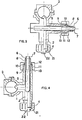
- the device essentially consists of a cross-shaped piece 1.
- the main conduit 2 has ends 3, 4 one of which is adapted to be connected to the supply line (not shown) by a collar and the other is provided with the dispensing device which is generally a nozzle or a spray nozzle.
- the dispensing device which is generally a nozzle or a spray nozzle.
- a commercially available nozzle for example a single-jet nozzle or a quadri-jet nozzle.
- a nozzle body 21 containing a single nozzle 22 is fixed to the device of the invention by means of a quick connection for example, a so-called “bayonet” connection.
- the device also comprises a secondary conduit 5 into which is introduced a sheath or flexible tube 6 passing through the main conduit 2.
- the outside diameter of the flexible tube 6 is slightly less than the diameter of the conduit 5 in order to allow the passage of the liquid to be sprayed, between the tube 6 and the inner wall of the conduit 2.
- a semi-rigid tube 8 is slid over the flexible tube 6 so as to engage against the shoulder 9 in the bicone connector 1.
- a ring 10 of biconical section and fitted on the semi-rigid tube is wedged between the end 11 of the bicone connection and the interior wall of the hollow nut 13.
- the ring 10 crushes the semi-rigid tube 8 and the tube 6 against the rigid tube 7.
- the semi-rigid material rigid tube 8 forms a seal thereby preventing the passage of the liquid to be sprayed to the outside.
- the design of the nozzle closure device of the present invention is simple and that it can consist of elements produced in large series and readily available on the market.
- the device may consist of a rigid synthetic material molded under pressure. It can also consist of a rigid material, for example brass, for the biconical fittings and a synthetic material for the main duct for the connections to the rail and for the fixing of the nozzles.
- the assembly of the two elements in separate materials can be carried out by screwing; it can also consist of an overmolding of the brass element with a synthetic material.
- the end 4 of the device of the invention is shown on an enlarged scale.
- This end comprises the main duct 2, the wall 23 of which is provided with a peripheral notch 25.
- the nozzle 22 is secured to the fixing element 27 assembled to the element 26 by screws or by rivets; the two elements are separated by a metal washer supporting a spring 24 which allows the engagement of lugs in said notch 25.
- the nozzle attached to the closure device is positioned correctly by means of grooves arranged longitudinally in the upper part of the wall 23 of the main duct 2.
- the element 26 is provided with lugs or other guide means making it possible to position the assembly 26 - 27 - 22 correctly.
- the device is sealed by an O-ring 28 which prevents the liquid to be sprayed from bypassing the attachment means of the nozzle.
- the spring 24 will be visible, thus ensuring that it is released by hand and / or by means of a suitable tool.
- This device has the advantage of allowing rapid replacement of one nozzle by another.
- the closure device of the present invention has the advantage over the known devices of not requiring a chamber and of not essentially modifying the direction of the liquid to be sprayed or spread, which significantly reduces the pressure drops in the spray liquid circuit, reduces the wear of the device and especially reduces the fouling resulting from the deposition of suspended, emulsion or solution materials in the liquid.
- the operator can control distance the closing of each sprayer separately or of two, three or more sprayers from one section of booms at the same time.
- the flexible tube 6 for closing the main conduit 2 has an end in the form of a finger that leads to the bottom of the conduit 5 closed by a plug, for example, or dead end.
- the spraying liquid undergoes a change of direction by following the main conduit 2.
- the secondary conduit 5 ends in said conduit 2 at the location of the angle formed by the two branches of the main duct.
- the closure is ensured by the flexible tube 6, the end of which is finger-shaped and which terminates in the main duct ending in the nozzle.
- the closure device of the invention also has the advantage that it is possible to maintain a continuous circulation and recycling of the spray liquid in the boom, towards the reservoir and then again from the reservoir to the booms, even when spraying is completely or partially stopped. In this way, the formation of deposits in the conduits through which the liquid passes is further reduced.
- the nozzle attachment device described allows, according to the invention, complete protection of the nozzle support by the particular end 4 of the nozzle closure device.
Landscapes
- Engineering & Computer Science (AREA)
- General Engineering & Computer Science (AREA)
- Mechanical Engineering (AREA)
- Catching Or Destruction (AREA)
- Nozzles (AREA)
- Organic Low-Molecular-Weight Compounds And Preparation Thereof (AREA)
Priority Applications (1)
| Application Number | Priority Date | Filing Date | Title |
|---|---|---|---|
| AT84900508T ATE23733T1 (de) | 1983-01-27 | 1984-01-25 | Abstellventil fuer duesen mit montagevorrichtung am spritzgestaenge. |
Applications Claiming Priority (2)
| Application Number | Priority Date | Filing Date | Title |
|---|---|---|---|
| LU84610 | 1983-01-27 | ||
| LU84610A LU84610A1 (fr) | 1983-01-27 | 1983-01-27 | Dispositif de fermeture de buses muni d'un moyen d'accrochage de buses pour rampe de pulverisation ou d'epandage |
Publications (2)
| Publication Number | Publication Date |
|---|---|
| EP0162046A1 EP0162046A1 (fr) | 1985-11-27 |
| EP0162046B1 true EP0162046B1 (fr) | 1986-11-20 |
Family
ID=19730025
Family Applications (2)
| Application Number | Title | Priority Date | Filing Date |
|---|---|---|---|
| EP84900508A Expired EP0162046B1 (fr) | 1983-01-27 | 1984-01-25 | Dispositif de fermeture de buses muni d'un moyen d'accrochage de buses pour rampe de pulverisation ou d'epandage |
| EP84200097A Pending EP0116984A1 (fr) | 1983-01-27 | 1984-01-25 | Dispositif de fermeture de buses muni d'un moyen d'accrochage de buses pour rampe de pulvérisation ou d'épandage |
Family Applications After (1)
| Application Number | Title | Priority Date | Filing Date |
|---|---|---|---|
| EP84200097A Pending EP0116984A1 (fr) | 1983-01-27 | 1984-01-25 | Dispositif de fermeture de buses muni d'un moyen d'accrochage de buses pour rampe de pulvérisation ou d'épandage |
Country Status (8)
| Country | Link |
|---|---|
| EP (2) | EP0162046B1 (da) |
| JP (1) | JPS60500223A (da) |
| AU (1) | AU2433284A (da) |
| BR (1) | BR8406914A (da) |
| DE (1) | DE3461390D1 (da) |
| DK (1) | DK155962C (da) |
| LU (1) | LU84610A1 (da) |
| WO (1) | WO1984002965A1 (da) |
Citations (1)
| Publication number | Priority date | Publication date | Assignee | Title |
|---|---|---|---|---|
| FR2151711A5 (da) * | 1971-09-10 | 1973-04-20 | Lestradet M C J |
Family Cites Families (8)
| Publication number | Priority date | Publication date | Assignee | Title |
|---|---|---|---|---|
| BE474638A (da) * | ||||
| FR1053752A (fr) * | 1948-07-23 | 1954-02-04 | Dispositif pour la coupure des conduites de gaz | |
| DE1035435B (de) * | 1955-12-09 | 1958-07-31 | Rheinisches Metallwerk Gmbh | Hilfsabsperrvorrichtung fuer Anbohrventile |
| FR1336067A (fr) * | 1960-05-17 | 1963-08-30 | Loing Verreries | Robinet à clapet gonflable |
| US3684177A (en) * | 1970-09-10 | 1972-08-15 | Transland Aircraft Inc | Spraying apparatus and control system therefor |
| US3890994A (en) * | 1973-08-20 | 1975-06-24 | Charles R Olsen | Normally open valve construction having a deformable bladder |
| FR2290254A1 (fr) * | 1974-11-07 | 1976-06-04 | Lestradet M C J | Dispositif de pulverisation pour rampe d'epandage destine notamment aux vehicules agricoles |
| GB2030474A (en) * | 1978-09-05 | 1980-04-10 | Dorman Sprayer Co Ltd | Spraying apparatus |
-
1983
- 1983-01-27 LU LU84610A patent/LU84610A1/fr unknown
-
1984
- 1984-01-25 EP EP84900508A patent/EP0162046B1/fr not_active Expired
- 1984-01-25 WO PCT/EP1984/000019 patent/WO1984002965A1/de not_active Ceased
- 1984-01-25 DE DE8484900508T patent/DE3461390D1/de not_active Expired
- 1984-01-25 BR BR8406914A patent/BR8406914A/pt not_active IP Right Cessation
- 1984-01-25 JP JP59500616A patent/JPS60500223A/ja active Pending
- 1984-01-25 AU AU24332/84A patent/AU2433284A/en not_active Abandoned
- 1984-01-25 EP EP84200097A patent/EP0116984A1/fr active Pending
- 1984-09-25 DK DK455884A patent/DK155962C/da not_active IP Right Cessation
Patent Citations (1)
| Publication number | Priority date | Publication date | Assignee | Title |
|---|---|---|---|---|
| FR2151711A5 (da) * | 1971-09-10 | 1973-04-20 | Lestradet M C J |
Also Published As
| Publication number | Publication date |
|---|---|
| DK155962C (da) | 1989-10-16 |
| DE3461390D1 (en) | 1987-01-08 |
| WO1984002965A1 (fr) | 1984-08-02 |
| AU2433284A (en) | 1984-08-15 |
| DK155962B (da) | 1989-06-05 |
| DK455884A (da) | 1984-09-25 |
| LU84610A1 (fr) | 1984-10-24 |
| EP0116984A1 (fr) | 1984-08-29 |
| EP0162046A1 (fr) | 1985-11-27 |
| JPS60500223A (ja) | 1985-02-21 |
| BR8406914A (pt) | 1985-05-21 |
| DK455884D0 (da) | 1984-09-25 |
Similar Documents
| Publication | Publication Date | Title |
|---|---|---|
| FR2537892A1 (fr) | Pulverisateur aspirant | |
| EP3479906B1 (fr) | Buse de pulvérisation avec rétrécissement de pré-atomisation, et tête de pulvérisation et dispositif de pulvérisation comprenant une telle buse | |
| FR2900583A1 (fr) | Pulverisateur de texture | |
| US6053427A (en) | Sprayer nozzle fluid supply system | |
| FR2824721A1 (fr) | Perfectionnement aux dispositifs de nettoyage par aspiration | |
| WO2015063295A1 (fr) | Dispositif d'alimentation d'un projecteur en produit de revetement liquide | |
| WO2014020254A1 (fr) | Dispositif de nettoyage pour pistolet de pulverisation | |
| FR2770279A1 (fr) | Adaptateur de tuyau et reservoir de pulverisation pourvu d'un tel adaptateur de tuyau | |
| EP0162046B1 (fr) | Dispositif de fermeture de buses muni d'un moyen d'accrochage de buses pour rampe de pulverisation ou d'epandage | |
| FR3025279A1 (fr) | Connecteur de valve pour une valve d'un dispositif de gonflage, et adaptateur comportant celui-ci | |
| US10514122B2 (en) | Combination spray nozzle/QD connector assembly for filling firefighter backpack bladders | |
| FR2903027A1 (fr) | Pistolet automatique de pulverisation | |
| FR2516348A1 (fr) | Circuit de distribution d'un liquide pour un appareil de pulverisation a usage agricole avec conduite pour fluide de nettoyage des buses | |
| FR2625544A1 (fr) | Conduit de forme particuliere destine a la micro-irrigation des sols par des appareils distributeurs ou goutteurs | |
| FR2630777A1 (fr) | Dispositif d'aspersion intermittente des pics d'une tete de havage | |
| FR2525924A1 (fr) | Pistolet de pulverisation a air | |
| FR2587631A1 (fr) | Dispositif de reglage du debit de l'air dans un pistolet a peinture | |
| FR2674773A1 (fr) | Pistolet automatique pour projeter un produit de revetement sur des objets. | |
| FR3141082A3 (fr) | Adaptateur de pulvérisation prévu pour équiper un porte-buse | |
| FR3063295A3 (fr) | Robinet a une seule entree a jet de brouillard et embout mousseur pour ledit robinet | |
| EP1867396A1 (fr) | Dispositif pistolet à peinture utilisant des cartouches aérosols | |
| FR2540405A3 (fr) | Rampe de pulverisation pour l'agriculture | |
| EP0284512B1 (fr) | Dispositif d'alimentation par gravité pour pistolet de pulvérisation de peinture ou de produit analogue | |
| FR2951656A1 (fr) | Manchon souple pour appareil de pulverisation | |
| FR2522537A1 (fr) | Buse de pulverisation a chambre de turbulence |
Legal Events
| Date | Code | Title | Description |
|---|---|---|---|
| PUAI | Public reference made under article 153(3) epc to a published international application that has entered the european phase |
Free format text: ORIGINAL CODE: 0009012 |
|
| 17P | Request for examination filed |
Effective date: 19841218 |
|
| AK | Designated contracting states |
Designated state(s): AT BE CH DE FR GB LI LU NL SE |
|
| RBV | Designated contracting states (corrected) |
Designated state(s): AT BE CH DE FR GB IT LI LU NL SE |
|
| XX | Miscellaneous (additional remarks) |
Free format text: VERBUNDEN MIT 84200097.8/0116984 (EUROPAEISCHE ANMELDENUMMER/VEROEFFENTLICHUNGSNUMMER) DURCH ENTSCHEIDUNG VOM 20.12.85. |
|
| 17Q | First examination report despatched |
Effective date: 19860203 |
|
| GRAA | (expected) grant |
Free format text: ORIGINAL CODE: 0009210 |
|
| AK | Designated contracting states |
Kind code of ref document: B1 Designated state(s): AT BE CH DE FR GB IT LI LU NL SE |
|
| PG25 | Lapsed in a contracting state [announced via postgrant information from national office to epo] |
Ref country code: AT Effective date: 19861120 |
|
| REF | Corresponds to: |
Ref document number: 23733 Country of ref document: AT Date of ref document: 19861215 Kind code of ref document: T |
|
| XX | Miscellaneous (additional remarks) |
Free format text: VERBUNDEN MIT 84200097.8/0116984 (EUROPAEISCHE ANMELDENUMMER/VEROEFFENTLICHUNGSNUMMER) DURCH ENTSCHEIDUNG VOM 20.12.85. |
|
| PG25 | Lapsed in a contracting state [announced via postgrant information from national office to epo] |
Ref country code: SE Effective date: 19861130 |
|
| REF | Corresponds to: |
Ref document number: 3461390 Country of ref document: DE Date of ref document: 19870108 |
|
| PG25 | Lapsed in a contracting state [announced via postgrant information from national office to epo] |
Ref country code: LU Free format text: LAPSE BECAUSE OF NON-PAYMENT OF DUE FEES Effective date: 19870131 |
|
| ITF | It: translation for a ep patent filed | ||
| PLBE | No opposition filed within time limit |
Free format text: ORIGINAL CODE: 0009261 |
|
| STAA | Information on the status of an ep patent application or granted ep patent |
Free format text: STATUS: NO OPPOSITION FILED WITHIN TIME LIMIT |
|
| 26N | No opposition filed | ||
| PGFP | Annual fee paid to national office [announced via postgrant information from national office to epo] |
Ref country code: NL Payment date: 19890131 Year of fee payment: 7 |
|
| PGFP | Annual fee paid to national office [announced via postgrant information from national office to epo] |
Ref country code: LU Payment date: 19900110 Year of fee payment: 7 |
|
| PGFP | Annual fee paid to national office [announced via postgrant information from national office to epo] |
Ref country code: CH Payment date: 19900130 Year of fee payment: 7 |
|
| PGFP | Annual fee paid to national office [announced via postgrant information from national office to epo] |
Ref country code: GB Payment date: 19910121 Year of fee payment: 8 |
|
| PGFP | Annual fee paid to national office [announced via postgrant information from national office to epo] |
Ref country code: BE Payment date: 19910122 Year of fee payment: 8 |
|
| ITTA | It: last paid annual fee | ||
| PG25 | Lapsed in a contracting state [announced via postgrant information from national office to epo] |
Ref country code: LI Effective date: 19910131 Ref country code: CH Effective date: 19910131 |
|
| PGFP | Annual fee paid to national office [announced via postgrant information from national office to epo] |
Ref country code: DE Payment date: 19910202 Year of fee payment: 8 |
|
| PG25 | Lapsed in a contracting state [announced via postgrant information from national office to epo] |
Ref country code: NL Effective date: 19910801 |
|
| NLV4 | Nl: lapsed or anulled due to non-payment of the annual fee | ||
| REG | Reference to a national code |
Ref country code: CH Ref legal event code: PL |
|
| PG25 | Lapsed in a contracting state [announced via postgrant information from national office to epo] |
Ref country code: GB Effective date: 19920125 |
|
| PG25 | Lapsed in a contracting state [announced via postgrant information from national office to epo] |
Ref country code: BE Effective date: 19920131 |
|
| BERE | Be: lapsed |
Owner name: GENTET CLEMENT Effective date: 19920131 |
|
| GBPC | Gb: european patent ceased through non-payment of renewal fee | ||
| PG25 | Lapsed in a contracting state [announced via postgrant information from national office to epo] |
Ref country code: DE Effective date: 19921001 |
|
| PGFP | Annual fee paid to national office [announced via postgrant information from national office to epo] |
Ref country code: FR Payment date: 19990107 Year of fee payment: 16 |
|
| PG25 | Lapsed in a contracting state [announced via postgrant information from national office to epo] |
Ref country code: FR Free format text: LAPSE BECAUSE OF NON-PAYMENT OF DUE FEES Effective date: 20000929 |
|
| REG | Reference to a national code |
Ref country code: FR Ref legal event code: ST |