EP0161812A2 - Mehrwegspritzdüse und Spritzverfahren - Google Patents
Mehrwegspritzdüse und Spritzverfahren Download PDFInfo
- Publication number
- EP0161812A2 EP0161812A2 EP85302615A EP85302615A EP0161812A2 EP 0161812 A2 EP0161812 A2 EP 0161812A2 EP 85302615 A EP85302615 A EP 85302615A EP 85302615 A EP85302615 A EP 85302615A EP 0161812 A2 EP0161812 A2 EP 0161812A2
- Authority
- EP
- European Patent Office
- Prior art keywords
- flow
- pressure
- channel
- stream
- manifold
- Prior art date
- Legal status (The legal status is an assumption and is not a legal conclusion. Google has not performed a legal analysis and makes no representation as to the accuracy of the status listed.)
- Granted
Links
- 238000001125 extrusion Methods 0.000 title claims abstract description 25
- 238000000034 method Methods 0.000 title claims description 8
- 230000008569 process Effects 0.000 title claims description 8
- 229920001169 thermoplastic Polymers 0.000 claims abstract description 22
- 239000004416 thermosoftening plastic Substances 0.000 claims abstract description 22
- 230000000694 effects Effects 0.000 description 15
- 239000012815 thermoplastic material Substances 0.000 description 13
- 229920005989 resin Polymers 0.000 description 7
- 239000011347 resin Substances 0.000 description 7
- 230000004044 response Effects 0.000 description 6
- 238000003475 lamination Methods 0.000 description 4
- 230000008901 benefit Effects 0.000 description 3
- 238000011144 upstream manufacturing Methods 0.000 description 3
- 230000002411 adverse Effects 0.000 description 2
- 230000006872 improvement Effects 0.000 description 2
- 239000000463 material Substances 0.000 description 2
- 239000004952 Polyamide Substances 0.000 description 1
- 239000004743 Polypropylene Substances 0.000 description 1
- 239000004793 Polystyrene Substances 0.000 description 1
- 229920001328 Polyvinylidene chloride Polymers 0.000 description 1
- 238000010276 construction Methods 0.000 description 1
- 229920001577 copolymer Polymers 0.000 description 1
- 230000003247 decreasing effect Effects 0.000 description 1
- 230000007547 defect Effects 0.000 description 1
- 229920001903 high density polyethylene Polymers 0.000 description 1
- 239000004700 high-density polyethylene Substances 0.000 description 1
- 229920001684 low density polyethylene Polymers 0.000 description 1
- 239000004702 low-density polyethylene Substances 0.000 description 1
- 229940099514 low-density polyethylene Drugs 0.000 description 1
- 229920002239 polyacrylonitrile Polymers 0.000 description 1
- 229920002647 polyamide Polymers 0.000 description 1
- 229920000515 polycarbonate Polymers 0.000 description 1
- 239000004417 polycarbonate Substances 0.000 description 1
- -1 polypropylene Polymers 0.000 description 1
- 229920001155 polypropylene Polymers 0.000 description 1
- 229920002223 polystyrene Polymers 0.000 description 1
- 229920002689 polyvinyl acetate Polymers 0.000 description 1
- 239000011118 polyvinyl acetate Substances 0.000 description 1
- 239000004800 polyvinyl chloride Substances 0.000 description 1
- 229920000915 polyvinyl chloride Polymers 0.000 description 1
- 239000005033 polyvinylidene chloride Substances 0.000 description 1
- 230000001105 regulatory effect Effects 0.000 description 1
- 230000008542 thermal sensitivity Effects 0.000 description 1
Images


Classifications
-
- B—PERFORMING OPERATIONS; TRANSPORTING
- B29—WORKING OF PLASTICS; WORKING OF SUBSTANCES IN A PLASTIC STATE IN GENERAL
- B29C—SHAPING OR JOINING OF PLASTICS; SHAPING OF MATERIAL IN A PLASTIC STATE, NOT OTHERWISE PROVIDED FOR; AFTER-TREATMENT OF THE SHAPED PRODUCTS, e.g. REPAIRING
- B29C48/00—Extrusion moulding, i.e. expressing the moulding material through a die or nozzle which imparts the desired form; Apparatus therefor
- B29C48/25—Component parts, details or accessories; Auxiliary operations
- B29C48/30—Extrusion nozzles or dies
- B29C48/305—Extrusion nozzles or dies having a wide opening, e.g. for forming sheets
- B29C48/31—Extrusion nozzles or dies having a wide opening, e.g. for forming sheets being adjustable, i.e. having adjustable exit sections
-
- B—PERFORMING OPERATIONS; TRANSPORTING
- B29—WORKING OF PLASTICS; WORKING OF SUBSTANCES IN A PLASTIC STATE IN GENERAL
- B29C—SHAPING OR JOINING OF PLASTICS; SHAPING OF MATERIAL IN A PLASTIC STATE, NOT OTHERWISE PROVIDED FOR; AFTER-TREATMENT OF THE SHAPED PRODUCTS, e.g. REPAIRING
- B29C48/00—Extrusion moulding, i.e. expressing the moulding material through a die or nozzle which imparts the desired form; Apparatus therefor
- B29C48/03—Extrusion moulding, i.e. expressing the moulding material through a die or nozzle which imparts the desired form; Apparatus therefor characterised by the shape of the extruded material at extrusion
- B29C48/07—Flat, e.g. panels
- B29C48/08—Flat, e.g. panels flexible, e.g. films
-
- B—PERFORMING OPERATIONS; TRANSPORTING
- B29—WORKING OF PLASTICS; WORKING OF SUBSTANCES IN A PLASTIC STATE IN GENERAL
- B29C—SHAPING OR JOINING OF PLASTICS; SHAPING OF MATERIAL IN A PLASTIC STATE, NOT OTHERWISE PROVIDED FOR; AFTER-TREATMENT OF THE SHAPED PRODUCTS, e.g. REPAIRING
- B29C48/00—Extrusion moulding, i.e. expressing the moulding material through a die or nozzle which imparts the desired form; Apparatus therefor
- B29C48/16—Articles comprising two or more components, e.g. co-extruded layers
- B29C48/18—Articles comprising two or more components, e.g. co-extruded layers the components being layers
- B29C48/21—Articles comprising two or more components, e.g. co-extruded layers the components being layers the layers being joined at their surfaces
-
- B—PERFORMING OPERATIONS; TRANSPORTING
- B29—WORKING OF PLASTICS; WORKING OF SUBSTANCES IN A PLASTIC STATE IN GENERAL
- B29C—SHAPING OR JOINING OF PLASTICS; SHAPING OF MATERIAL IN A PLASTIC STATE, NOT OTHERWISE PROVIDED FOR; AFTER-TREATMENT OF THE SHAPED PRODUCTS, e.g. REPAIRING
- B29C48/00—Extrusion moulding, i.e. expressing the moulding material through a die or nozzle which imparts the desired form; Apparatus therefor
- B29C48/25—Component parts, details or accessories; Auxiliary operations
- B29C48/255—Flow control means, e.g. valves
- B29C48/2556—Flow control means, e.g. valves provided in or in the proximity of dies
-
- B—PERFORMING OPERATIONS; TRANSPORTING
- B29—WORKING OF PLASTICS; WORKING OF SUBSTANCES IN A PLASTIC STATE IN GENERAL
- B29C—SHAPING OR JOINING OF PLASTICS; SHAPING OF MATERIAL IN A PLASTIC STATE, NOT OTHERWISE PROVIDED FOR; AFTER-TREATMENT OF THE SHAPED PRODUCTS, e.g. REPAIRING
- B29C48/00—Extrusion moulding, i.e. expressing the moulding material through a die or nozzle which imparts the desired form; Apparatus therefor
- B29C48/25—Component parts, details or accessories; Auxiliary operations
- B29C48/30—Extrusion nozzles or dies
- B29C48/305—Extrusion nozzles or dies having a wide opening, e.g. for forming sheets
- B29C48/307—Extrusion nozzles or dies having a wide opening, e.g. for forming sheets specially adapted for bringing together components, e.g. melts within the die
Definitions
- the present invention relates to the melt-lamination of thermoplastic materials. More specifically, this invention relates to overcoming the curtaining effect, and in addition to providing for convergence of molten thermoplastic streams at substantially equal flow velocities without external.die adjustment.
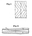
- FIG. 1 depicts a two-layer laminate of thermoplastic materials, in which the curtaining effect is shown to be present in both layers.
- the convergence of molten thermoplastic streams at substantially equal flow velocities in an extrusion die is known.
- a problem is that external adjustment of the die is required.
- the present invention is concerned with overcoming these problems in a multimanifold extrusion die.
- extrusion nozzle having a central tongue separating two flow passages that terminate at a discharge slot.
- the feed channels for the molten thermoplastic materials and/or the longitudinal slits connected to these channels are of such a construction that their cross-section is reduced toward the center of the channels and/or slits, and it is stated that this causes an improvement of the distribution of pressure in the material issuing from the extruders, so that very uniform layers are produced.
- a molten thermoplastic stream flows through a pair of distribution channels joined by a narrow flow passage channel.
- a co-axial tubular extrusion die that has a flow restriction in the flow path of the lower viscosity resin to increase the pressure drop of the resin as it passes through the die. Separating the two flow paths of this die is a divider having a wall that in part forms the flow restriction.
- a multimanifold coextrusion die having an adjustable divider provided between any two of the flow channels thereof.
- Each flow channel includes a back pressure cavity and a flow restriction channel located between the back pressure cavity and the point of convergence of the flow channels.
- This coextrusion die provides for adjustment of flow restriction channel width, by manipulation of the adjustable divider.
- the molten thermoplastic streams can thus converge at substantially equal flow velocities, and there can be laminar flow at the point of convergence.
- the layers of a laminate thus produced may exhibit the curtaining effect.
- external adjustment of the divider is required.
- a multi-manifold extrusion die comprises first and second flow channels which traverse the die and converge at a point of convergence within the die, and a freely-pivoting divider disposed between the flow channels.
- Each of the flow channels includes a manifold chamber situated upstream from the divider, and further includes in descending downstream order, a pressure compensating restriction channel, an expansion chamber, and a tapered flow restriction channel.
- the pressure compensating restriction channel is formed in part by a head portion of the divider.
- the expansion chamber has a cross-sectional area greater than that of any cross-section of the pressure compensating restriction channel, and is also of greater cross-sectional area than the tapered flow restriction channel.
- the manifold chamber has a longitudinal dimension of sufficient magnitude that a molten thermoplastic stream exiting from the manifold chamber is at a relatively greater pressure at a side-to-side midpoint than at the sides thereof.
- the pressure compensating restriction channel is of increasing cross-sectional area from the center to each end thereof so as to provide inverse resistance to flow whereby the molten stream, which is flowing at relatively greater pressure at the midpoint prior to flowing through the pressure compensating restriction channel, is caused to exit from this channel at substantially equal pressure from side to side.
- the expansion chamber and the tapered flow restriction channel each have a longitudinal dimension that maintains the molten stream at the substantially equal flow pressure.
- a molten stream exits at the substantially equal flow pressure from the tapered flow restriction channel of each of the flow channels. Convergence of the molten streams forms a layered melt stream that flows at substantially equal pressure from side to side.
- the free floating divider automatically pivots in response to any difference between the flow rates of the molten streams. As a result, convergence of the streams is at substantially equal flow velocities.
- Also provided by the present invention is a process using a multimanifold extrusion die that minimizes or eliminates the curtaining effect in the melt-lamination of thermoplastic materials.
- This process includes subjecting a molten thermoplastic stream that is flowing at a relatively greater pressure at a side-to-side midpoint than at the sides thereof, to an inverse resistance to flow whereby the molten stream is caused to flow at substantially equal pressure from side to side.
- the cross-sectional thickness of the molten stream is then expanded, while the substantially equal flow pressure is maintained.
- the cross-sectional thickness of the expanded stream is thinned to a desired cross-sectional dimension, while the substantially equal flow pressure is still maintained.
- the thinned molten stream is then converged with at least one other thinned stream that is flowing at substantially equal pressure from side to side.
- the substantially equal flow pressure is maintained for each stream of the resulting melt-laminate until the melt-laminate exits from the extrusion die.
- the present invention is directed to an improved multimanifold extrusion die and to an improved process for the melt-lamination of thermoplastic materials. More particularly, this invention minimises or eliminates the curtaining effect, a well known defect in the layers of a thermoplastic laminate.
- a longfelt need met by the present invention is that it minimises or eliminates the curtaining effect, while at the same time it retains the advances in the art provided by the prior art die of Figure 3 of U.S. Patents 4,152,387 and 4,197,069.
- this improved die does not require external adjustment for convergence of molten thermoplastic streams at substantially equal flow velocities. Rather, it has a self-balancing feature.
- thermoplastic materials include, but are not limited to, low- and high-density polyethylene, polypropylene, polycarbonates, polyamides, polyvinyl chloride, polyvinylidene chloride, polystyrene, polyvinylacetate, polyacrylonitrile and copolymers thereof.
- Die 10 provides for the passage of three thermoplastic streams through flow channels 12, 14 and 16, and for the convergence of these streams at a point of convergence 18 to form a three layer melt-laminate. It will be understood that a die in accordance with the present invention may be used to form, for example, a two layer, five layer or seven layer laminate, or may even be used to form a laminate having a greater number of layers.
- the melt-laminate is passed through an exit channel that consists of a preland channel 20, which is advantageously tapered, and a land channel 22, which typically has parallel walls when viewed in cross-section.
- the melt-laminate exits from the exit channel of die 10 at an opening 24.
- a free floating, pivoting divider or vane blade 26 Situated between flow channels 12 and 14 is a free floating, pivoting divider or vane blade 26 and between flow channels 14 and 16 is a free floating, pivoting divider or vane blade 28.
- Dividers 26 and 28 have head portions 30 and 32, and point portions 34 and 36, as shown.
- At one end of each divider is a round shaft (not shown), which pivots in a bearing (also not shown).
- Each divider is permitted to pivot freely in response to any difference-between the flow rates of the molten streams passing through the adjacent flow channels, which are, for example, channels 12 and 14 in the case of divider 26.
- Each flow channel includes a manifold chamber, shown as 46, 48 and 50; a pressure compensating restriction channel, indicated as 52, 54 and 56; an expansion chamber, designated as 58, 60 and 62; and a flow restriction channel, numbered as 64, 66 and 68.
- Manifold chamber or manifold 46 is located upstream from divider 26 and is a coat-hanger type manifold, that is, it has a cross-sectional area that diminishes from the center to each end thereof. This characteristic of manifold 46 is revealed by comparison of the cross-sectional area of manifold 46 in Figure 3 with the cross-sectional area of manifold 46 in Figure 2, which shows an end 70 of manifold 46.
- the manifold may be of constant or variable cross-section depending upon, for example, individual thermoplastic material requirements.
- a manifold having a constant cross-section from end to end is known as a keyhole type manifold.
- the residence time of a thermoplastic material is greater in a keyhole type manifold than in a coat-hanger type manifold. Accordingly, the latter type is preferred where, for example, it is advantageous for residence time to be as short as possible due to, for purposes of illustration, thermal sensitivity.
- the coat-hanger type may be preferred over the keyhole type for the reason that a previously used thermoplastic material is more rapidly cleaned from this manifold, as a new thermoplastic material flows through.
- transverse flow of a molten stream occurs as a result of which the stream is longitudinally distributed over the entire length of the manifold.
- the longitudinal dimension of a manifold of multimanifold die 10 is of considerable magnitude, that is, typically of 0.25 to 1.5 m (or more), the effect being that a stream exiting from the manifold is at a relatively greater pressure at a side-to-side midpoint than at the sides thereof.
- manifold 46 has a smaller cross-sectional area than manifold 48 for the reason that a higher material throughput through manifold 48 is desired in die 10.
- Pressure compensating restriction channel 52 is located downstream from manifold 46 and is formed by a longitudinal wall 72 of head portion 30 of divider 26 and an inner wall 74 of die 10.
- Channel 52 is especially characterised by having increasing cross-sectional area from center 76 thereof to each end of the channel, with an end 78 being shown in Figure 2.
- This feature of the channel is further illustrated in Figure 4 in the case of pressure compensating restriction channel 54, with arrows being used in the Figure to designate the width at the center of channel 54.
- the dimensions of a pressure compensating restriction channel are to be varied depending upon whether a resin of relatively higher or lower viscosity (dotted lines in Figure 4 represent the dimensions for the lower viscosity resin) is to be passed through the channel.
- variable cross-sectional area of channel 52 provides inverse resistance to flow to the thermoplastic stream that has exited from manifold 46 at a relatively greater pressure at a side-to-side midpoint than at the sides thereof.
- the precise cross-sectional dimension to be used for channel 52 is selected with regard to the viscosity of the particular resin to be passed through this channel so as to cause the molten stream to exit from channel 52 at substantially equal pressure from side to side.
- this channel subjects the molten stream to an inverse resistance to flow in such a way as to cause the stream to flow at substantially equal pressure from side to side. I believe that this is a necessary aspect of minimising or eliminating the curtaining effect in a die.
- channel 52 when viewed in cross-section, is tapered in the direction of flow, regardless of whether downstream flow restriction channel 64 is at a minimum ( Figure 6) or maximum ( Figure 5) flow restriction, and that it provides relatively greater flow restriction when channel 64 is at the maximum flow restriction.
- channel 52 when viewed in cross-section, may be parallel when channel 64 is at the minimum flow restriction.
- the necessary configuration from both a longitudinal and cross-sectional standpoint, is provided to channel 52 by longitudinal wall 72, with divider 26 typically having been machined to form this wall.
- the pressure compensating restriction channel feeds the molten thermoplastic stream, which is now flowing at a pressure that is substantially equal from side to side, to expansion chamber 58.
- This chamber has a cross-sectional area that is greater than the area of any cross-section of channel 52.
- chamber 58 which is beneficially of substantially constant cross-sectional area from end to end, will be typically considerably greater in cross-sectional area than channel 52, as is illustrated in Figure 2 and 3.
- an important function provided by chamber 58 is that of expanding the thickness of the flowing molten stream so that, for example, the stream can be subsequently metered by flow restriction channel 64 to a desired cross-sectional thickness.
- Expansion chamber 58 is formed by longitudinal wall 72 of an intermediate portion of divider 26 and inner wall 74 of die 10.
- An essential characteristic of the chamber is that it has a longitudinal dimension that maintains the molten stream at substantially equal pressure from side to side.
- chamber 58 will characteristically have the same longitudinal dimension as manifold chamber 46. It is possible, however, that there could be a minor deviation in the longitudinal dimension, provided that the substantially equal flow pressure effected by channel 52, is not adversely disturbed as the molten stream flows through expansion chamber 58.
- chamber 58 functions to expand the thickness of the flowing stream, while maintaining the stream at the substantially equal flow pressure. Moreover, it may be observed from Figures 2 and 3, that whereas the upper portion of chamber 58 is so configured as to provide for expansion of the stream thickness, the lower portion of the chamber is tapered, when viewed in cross-section, in the direction of flow restriction channel 64, with which it merges to provide a channel for the molten stream to flow to point of convergence 18.
- Flow restriction channel 64 is also tapered, when viewed in cross-section, in the direction of point of convergence 18. This channel is of smaller cross-sectional area than chamber 58, and thus serves to thin the cross-sectional thickness of the expanded molten stream.
- Channel 64 which is advantageously of substantially constant cross-sectional area from end to end, is formed by longitudinal wall 72 of point portion 34 of divider 26 and inner wall 74 of die 10.
- the cross-sectional dimension of channel 64 is precisely regulated by pivoting of vane blade 26 in response to any difference between the flow rates of the molten streams passing through flow channels 12 and 14.
- the free floating vane blade is self balancing: it provides for a relatively wider channel 64 than 66 in response to a relatively higher viscosity molten stream in channel 12 than 14, for example.
- Channel 64 has a longitudinal dimension that maintains the molten stream at the substantially equal flow pressure. Accordingly, this channel will typically have substantially the same longitudinal dimension as manifold chamber 46. Again, conceivably there could be a slight variation in the longitudinal dimension, provided that the substantially equal flow pressure of the molten stream is not adversely disturbed as it passes through this channel.
- flow restriction channel 64 From the above description of flow restriction channel 64, it will be understood that the molten stream exits from this channel at substantially equal flow pressure from side to side. Moreover, it will be understood that channel 64 functions to thin the expanded molten stream to a desired cross-sectional area, while maintaining the stream at the substantially equal flow pressure.
- the present invention concomitantly makes possible a further improvement: it provides for convergence of molten thermoplastic streams at substantially equal flow velocities without external adjustment of the die.
- This additional advance in the art is a further benefit of the configuration that I give to each flow channel for the purpose of minimising or eliminating the curtaining effect.
- the configuration of the manifold chamber, the pressure compensating restriction channel, the expansion chamber and the tapered flow restriction channel enables the vanes to be free floating and pivot in response to a flow rate differential.
- each divider is removable and may be replaced with an inter-changeable divider, in order to provide die 10 with a pressure compensating restriction channel having a configuration precisely suited to the viscosity of a molten resin to be passed through the channel. This avoids the necessity of otherwise using a completely different die having a pressure compensating restriction channel of the needed configuration. This advantage will reduce cost in terms of both time and money.
- the layers of a laminated product made by use of the adaptor exhibit the curtaining effect even though a molten stream exerts equal pressure along the length of the elongated flow restriction channel thereof.
- a molten thermoplastic stream enters flow channel 12, and passes through manifold chamber 4 6 , in which it is longitudinally spread and out of which it flows at relatively greater pressure at a side-to-side midpoint than at the sides thereof.
- the molten stream next passes through pressure compensating restriction channel 52, which subjects the stream to an inverse resistance to flow as a result of which the stream leaves channel 52 flowing at substantially equal pressure from side to side.
- the stream then passes through expansion chamber 58, in which the cross-sectional thickness of the stream is expanded, while the substantially equal flow pressure is maintained.
- the expanded stream is subsequently passed through flow restriction channel 64, in which the cross-sectional thickness is thinned to a desired cross-sectional dimension.
- the thinned molten stream is converged at point of convergence 18 with two other molten streams each of which is also flowing at substantially equal pressure from side to side. At the point of convergence, the molten streams have substantially equal velocities.
- the resulting melt-laminate is passed through preland channel 20, then through land channel 22, and finally exits from die 10 at opening 24.
- the essential steps are as follows.
- a molten thermoplastic stream that is flowing at a relatively greater pressure at a side-to-side midpoint than at the sides thereof, is subjected to an inverse resistance to flow whereby the molten stream is caused to flow at substantially equal pressure from side to side.
- the thickness of the stream is then expanded, while the substan- t tially equal flow pressure is maintained. With this flow pressure continuing to be maintained, the cross-sectional thickness of the expanded stream is thinned to a desired cross-sectional dimension.
- the thinned molten stream is converged with at least one other thinned molten stream that is flowing at substantially equal pressure from side to side to form a melt-laminate.
- the substantially equal flow pressure of each stream in the melt-laminate is then maintained until the melt-laminate exits from the die.
- this last step is achieved by providing the exit channel with a longitudinal dimension that maintains each layer of the melt-laminate at the substantially equal flow pressure.
- the exit channel will have the same longitudinal dimension as any of the manifold chambers, which characteristically will all have the same longitudinal dimension.
- each of the divider head portions provided with an adjusting device, shown as 38 and 40.
- these adjusting devices are not necessary, as the dividers are free floating and provide any required adjustment in the relative widths of the adjacent flow channels in response to any flow rate differential.
- Arrows 42 and 44 show that these adjusting devices could be moved clockwise or counterclockwise.
- Flow instability between the layered melt streams of the melt-laminate may be reduced by locating point of convergence 18 as close as possible to opening 24, that is, by making the exit channel as short as possible, for example, about 40 mm. Otherwise, the exit channel may be, for the purposes of illustration, about 100-150 mm.
Landscapes
- Engineering & Computer Science (AREA)
- Mechanical Engineering (AREA)
- Manufacturing & Machinery (AREA)
- Extrusion Moulding Of Plastics Or The Like (AREA)
Applications Claiming Priority (4)
| Application Number | Priority Date | Filing Date | Title |
|---|---|---|---|
| US60096184A | 1984-04-16 | 1984-04-16 | |
| US600961 | 1984-04-16 | ||
| US604995 | 1984-04-27 | ||
| US06/604,995 US4533308A (en) | 1984-04-16 | 1984-04-27 | Multimanifold extrusion die and coextrusion process |
Publications (3)
| Publication Number | Publication Date |
|---|---|
| EP0161812A2 true EP0161812A2 (de) | 1985-11-21 |
| EP0161812A3 EP0161812A3 (en) | 1986-05-28 |
| EP0161812B1 EP0161812B1 (de) | 1989-07-05 |
Family
ID=27083762
Family Applications (1)
| Application Number | Title | Priority Date | Filing Date |
|---|---|---|---|
| EP85302615A Expired EP0161812B1 (de) | 1984-04-16 | 1985-04-15 | Mehrwegspritzdüse und Spritzverfahren |
Country Status (6)
| Country | Link |
|---|---|
| US (1) | US4533308A (de) |
| EP (1) | EP0161812B1 (de) |
| BR (1) | BR8501789A (de) |
| CA (1) | CA1240467A (de) |
| DE (1) | DE3571306D1 (de) |
| MX (1) | MX165888B (de) |
Cited By (7)
| Publication number | Priority date | Publication date | Assignee | Title |
|---|---|---|---|---|
| EP0299736A1 (de) * | 1987-07-17 | 1989-01-18 | P.C.E. Corporation | Koextrusionsverfahren und -vorrichtung |
| EP1621320A1 (de) * | 2004-07-27 | 2006-02-01 | Reifenhäuser GmbH & Co. Maschinenfabrik | Koextrusionsadapter |
| US9216534B2 (en) | 2013-10-11 | 2015-12-22 | Nordson Corporation | Coextrusion feedblock and coextrusion profiling insert assembly |
| US9327441B2 (en) | 2011-10-06 | 2016-05-03 | Nordson Corporation | Adjustable feedblock |
| US20170259483A1 (en) * | 2016-03-11 | 2017-09-14 | Reifenhauser Gmbh & Co. Kg Maschinenfabrik | Coextrusion adapter |
| US9808980B2 (en) | 2014-07-29 | 2017-11-07 | Nordson Corporation | Coextrusion feedblock, coextrusion profiling insert assembly, and methods of operation |
| CN112192823A (zh) * | 2020-09-17 | 2021-01-08 | 江苏亨通光电股份有限公司 | 双异色条护套及其挤出模具 |
Families Citing this family (60)
| Publication number | Priority date | Publication date | Assignee | Title |
|---|---|---|---|---|
| US4669965A (en) * | 1983-09-08 | 1987-06-02 | Kabushiki Kaisha Plastic Kogaku Kenkyusho | Multi-layer extrusion die |
| US4574067A (en) * | 1985-03-01 | 1986-03-04 | Ball Corporation | Crosshead with static mixers |
| CH678507A5 (de) * | 1986-03-06 | 1991-09-30 | Maillefer Sa | |
| US4720252A (en) * | 1986-09-09 | 1988-01-19 | Kimberly-Clark Corporation | Slotted melt-blown die head |
| US4925380A (en) * | 1986-10-20 | 1990-05-15 | Kraft, Inc. | Multicolor confection extrusion system |
| US4738611A (en) * | 1987-03-04 | 1988-04-19 | Graham Engineering Corporation | Cross head die |
| US4789513A (en) * | 1987-06-05 | 1988-12-06 | P.C.E. Corp. | Coextrusion apparatus and process |
| US5066443A (en) * | 1990-04-11 | 1991-11-19 | P.C.E. Corp. | Dual barrier laminate process |
| US5110530A (en) * | 1990-09-07 | 1992-05-05 | W. R. Grace & Co.-Conn. | Striped film method |
| US5147195A (en) * | 1991-06-13 | 1992-09-15 | The Cloeren Company | Extrusion apparatus with adjustable flow-restricting member |
| US5324187A (en) * | 1991-06-28 | 1994-06-28 | Cook Warren R | Co-extrusion apparatus |
| US5284430A (en) * | 1991-08-27 | 1994-02-08 | Reynolds Consumer Products, Inc. | Apparatus for manufacture of integral reclosable bag |
| CA2082437C (en) * | 1991-11-14 | 1998-01-20 | Peter C. Gates | Spiral fed multi-layer tubular die |
| US5375990A (en) * | 1992-09-10 | 1994-12-27 | Extrusion Dies, Inc. | Feed block for coextrusion apparatus |
| EP0646450B1 (de) * | 1993-09-07 | 1998-11-11 | EXTRUSION DIES, Inc. | Vorrichtung zur Extrusion von thermoplastischen Kunststoffen |
| US5449281A (en) * | 1993-10-08 | 1995-09-12 | Nestec S.A. | Apparatus for preparing shaped co-extruded products |
| US5464577A (en) * | 1994-01-04 | 1995-11-07 | Minnesota Mining And Manufacturing Company | Method of thickness control for dies |
| US5686128A (en) * | 1995-08-31 | 1997-11-11 | Nabisco Technology Company | Apparatus and method for triple co-extruding a snack product |
| US5763047A (en) * | 1996-04-03 | 1998-06-09 | Olympic General Corporation | Blown-film textured liner having a smooth welding strip |
| US5843230A (en) * | 1996-07-02 | 1998-12-01 | Avery Dennison | Sealing system for improved applicator die |
| US5851566A (en) * | 1996-07-02 | 1998-12-22 | Avery Dennison | Applicator die |
| US5780067A (en) * | 1996-09-10 | 1998-07-14 | Extrusion Dies, Inc. | Adjustable coextrusion feedblock |
| US7087287B2 (en) * | 1997-02-21 | 2006-08-08 | The Procter & Gamble Company | Tear resistant porous extensible web |
| JP3931391B2 (ja) * | 1997-08-22 | 2007-06-13 | 富士フイルム株式会社 | 多層支持体の成形方法及びその成形ダイ装置 |
| US6206680B1 (en) | 1998-03-17 | 2001-03-27 | Extrusion Dies, Inc. | Extrusion die membrane |
| US6228462B1 (en) | 1998-05-15 | 2001-05-08 | The Procter & Gamble Company | Multilayer compression-resistant apertured web |
| US6927315B1 (en) | 1999-07-30 | 2005-08-09 | 3M Innovative Properties Company | Adhesive composite having distinct phases |
| US6447875B1 (en) * | 1999-07-30 | 2002-09-10 | 3M Innovative Properties Company | Polymeric articles having embedded phases |
| US6713174B2 (en) * | 1999-10-13 | 2004-03-30 | Arlin Mgf. Co., Inc. | Tear tape |
| US6352424B1 (en) | 1999-12-30 | 2002-03-05 | Extrusion Dies, Inc. | Extrusion die membrane assembly |
| US6626206B1 (en) | 2000-01-20 | 2003-09-30 | Extrusion Dies, Inc. | Feedblock for adjusting the dimensions of a set of co-extruded layers of a multi-layer sheet |
| EP1621169B2 (de) | 2000-04-07 | 2017-09-13 | The Procter & Gamble Company | Mit Öffnungen versehene Polymerfilmbahn und absorbierende Artikel, die diese enthalten |
| CN1273282C (zh) * | 2000-04-13 | 2006-09-06 | 奥利-本特·拉斯马森 | 在共挤压加工中接合薄片或条带形成流的方法与装置 |
| US20020076554A1 (en) * | 2000-12-15 | 2002-06-20 | Kimberly-Clark Worldwide, Inc. | Composite laminate for personal care product and method of making |
| US20030161977A1 (en) * | 2001-04-06 | 2003-08-28 | Douglas Sabin | Four layer nozzle for forming four layer articles |
| US6908581B2 (en) * | 2001-04-06 | 2005-06-21 | Kortec, Inc. | Optimized flow to prevent core layer breakthrough |
| JP2005530030A (ja) * | 2002-07-03 | 2005-10-06 | ザ プロクター アンド ギャンブル カンパニー | 放射線硬化性低応力緩和エラストマー材料 |
| AU2003284335A1 (en) * | 2002-10-24 | 2004-05-13 | 3M Innovative Properties Company | Methods of making high gain optical devices having a continuous and dispersive phase |
| JP4425668B2 (ja) * | 2004-03-01 | 2010-03-03 | 東洋鋼鈑株式会社 | 複層の無延伸フィルムの製造方法および複層樹脂被覆金属板の製造方法 |
| US20090072434A1 (en) * | 2007-09-14 | 2009-03-19 | Kotaro Takita | Coextrusion die and manifold system therefor |
| US20100123262A1 (en) * | 2008-11-18 | 2010-05-20 | Lewis Conrad Keller | Multi-orifice extrusion die and method for obtaining uniform flow |
| GB2478732B (en) | 2010-03-15 | 2014-08-20 | Kraft Foods R & D Inc | Improvements in injection moulding |
| US9277753B2 (en) | 2010-08-20 | 2016-03-08 | Frito-Lay North America, Inc. | Synchronized cutting and injection system and method |
| RU2569527C2 (ru) | 2010-11-02 | 2015-11-27 | Дзе Проктер Энд Гэмбл Компани | Разлагаемые упаковки-саше для развивающихся рынков |
| JP2014513752A (ja) | 2011-05-20 | 2014-06-05 | ザ プロクター アンド ギャンブル カンパニー | デンプン−ポリマー−ワックス−油組成物のフィルム |
| EP2710059A1 (de) | 2011-05-20 | 2014-03-26 | The Procter and Gamble Company | Folien aus polymerwachszusammensetzungen |
| EP2710061A1 (de) | 2011-05-20 | 2014-03-26 | The Procter and Gamble Company | Filme aus polymer-öl-zusammensetzungen |
| WO2014003761A1 (en) | 2012-06-28 | 2014-01-03 | Dow Global Technologies Llc | System, method and apparatus for producing a multi-layer, microcapillary film |
| US20140142232A1 (en) | 2012-11-20 | 2014-05-22 | The Procter & Gamble Company | Polymer-Grease Compositions and Methods of Making and Using the Same |
| CN104781332A (zh) | 2012-11-20 | 2015-07-15 | 宝洁公司 | 淀粉-热塑性聚合物-油脂组合物及其制备和使用方法 |
| EP2922678A1 (de) | 2012-11-20 | 2015-09-30 | iMFLUX Inc. | Verfahren zum formen thermoplastischer polymerzusammensetzungen mit hydroxylierten lipiden |
| CN104797646A (zh) | 2012-11-20 | 2015-07-22 | 宝洁公司 | 包含氢化蓖麻油的热塑性聚合物组合物、制备方法、以及由其制备的非迁移制品 |
| US20140138584A1 (en) | 2012-11-20 | 2014-05-22 | The Procter & Gamble Company | Polymer-Soap Compositions and Methods of Making and Using the Same |
| CN104781331A (zh) | 2012-11-20 | 2015-07-15 | 宝洁公司 | 淀粉-热塑性聚合物-皂组合物及其制备和使用方法 |
| US20140272370A1 (en) | 2013-03-15 | 2014-09-18 | The Procter & Gamble Company | Renewable Thermoplastic Starch-Polyolefin Compositions Comprising Compatibilizer and Flexible Thin Films Made Therefrom |
| WO2015066588A1 (en) | 2013-11-04 | 2015-05-07 | The Procter & Gamble Company | Thermoplastic polymer compositions having co-continuous plate-like morphology |
| MX2016015908A (es) | 2014-06-02 | 2017-04-11 | Procter & Gamble | Peliculas multiestratificadas de polimeros termoplasticos que comprenden acido polilactico. |
| US20170002116A1 (en) | 2015-06-30 | 2017-01-05 | The Procter & Gamble Company | Articles of Reclaimed Polypropylene Compositions |
| AR115620A1 (es) * | 2018-06-28 | 2021-02-10 | Dow Global Technologies Llc | Conjunto de matriz para producir una película |
| AT524541B1 (de) * | 2021-04-07 | 2022-07-15 | Engel Austria Gmbh | Vorrichtung zum Entgasen und Verfahren zum Entgasen einer plastifizierten Masse |
Citations (5)
| Publication number | Priority date | Publication date | Assignee | Title |
|---|---|---|---|---|
| FR1052780A (fr) * | 1951-01-20 | 1954-01-27 | Dynamit Nobel Ag | Procédé et dispositif pour la fabrication continue de feuilles et bandes sans fin en matières telles que les produits synthétiques thermoplastiques |
| GB1355046A (en) * | 1970-07-24 | 1974-06-05 | Ici Ltd | Die |
| DE1902317B2 (de) * | 1968-02-27 | 1979-02-01 | American Can Co., New York, N.Y. (V.St.A.) | Extruderkopf zum !Coextrudieren einer mehrschichtigen, aus thermoplastischen Kunststoffen bestehenden Verbundbahn |
| US4152387A (en) * | 1976-05-21 | 1979-05-01 | Peter Cloeren | Method for forming multi-layer laminates |
| US4197069A (en) * | 1976-05-21 | 1980-04-08 | Peter Cloeren | Variable thickness extrusion die |
Family Cites Families (5)
| Publication number | Priority date | Publication date | Assignee | Title |
|---|---|---|---|---|
| FR1568124A (de) * | 1968-02-13 | 1969-05-23 | ||
| US3584341A (en) * | 1969-09-22 | 1971-06-15 | Fmc Corp | Apparatus for making netlike structures |
| US3792945A (en) * | 1972-07-21 | 1974-02-19 | Rowland Prod Inc | Apparatus for producing multicolor patterns and sheet material produced thereby |
| US3877857A (en) * | 1972-12-20 | 1975-04-15 | Beloit Corp | Multiple melt chamber extrusion die |
| US4344907A (en) * | 1980-10-30 | 1982-08-17 | Mobil Oil Corporation | Method and apparatus providing uniform resin distribution in a coextruded product |
-
1984
- 1984-04-27 US US06/604,995 patent/US4533308A/en not_active Expired - Lifetime
-
1985
- 1985-04-15 MX MX204960A patent/MX165888B/es unknown
- 1985-04-15 BR BR8501789A patent/BR8501789A/pt not_active IP Right Cessation
- 1985-04-15 EP EP85302615A patent/EP0161812B1/de not_active Expired
- 1985-04-15 DE DE8585302615T patent/DE3571306D1/de not_active Expired
- 1985-04-15 CA CA000479137A patent/CA1240467A/en not_active Expired
Patent Citations (5)
| Publication number | Priority date | Publication date | Assignee | Title |
|---|---|---|---|---|
| FR1052780A (fr) * | 1951-01-20 | 1954-01-27 | Dynamit Nobel Ag | Procédé et dispositif pour la fabrication continue de feuilles et bandes sans fin en matières telles que les produits synthétiques thermoplastiques |
| DE1902317B2 (de) * | 1968-02-27 | 1979-02-01 | American Can Co., New York, N.Y. (V.St.A.) | Extruderkopf zum !Coextrudieren einer mehrschichtigen, aus thermoplastischen Kunststoffen bestehenden Verbundbahn |
| GB1355046A (en) * | 1970-07-24 | 1974-06-05 | Ici Ltd | Die |
| US4152387A (en) * | 1976-05-21 | 1979-05-01 | Peter Cloeren | Method for forming multi-layer laminates |
| US4197069A (en) * | 1976-05-21 | 1980-04-08 | Peter Cloeren | Variable thickness extrusion die |
Cited By (10)
| Publication number | Priority date | Publication date | Assignee | Title |
|---|---|---|---|---|
| EP0299736A1 (de) * | 1987-07-17 | 1989-01-18 | P.C.E. Corporation | Koextrusionsverfahren und -vorrichtung |
| EP1621320A1 (de) * | 2004-07-27 | 2006-02-01 | Reifenhäuser GmbH & Co. Maschinenfabrik | Koextrusionsadapter |
| US7384254B2 (en) | 2004-07-27 | 2008-06-10 | REIFENHäUSER GMBH & CO. MASCHINENFABRIK | Coextrusion adapter |
| US9327441B2 (en) | 2011-10-06 | 2016-05-03 | Nordson Corporation | Adjustable feedblock |
| US9216534B2 (en) | 2013-10-11 | 2015-12-22 | Nordson Corporation | Coextrusion feedblock and coextrusion profiling insert assembly |
| US9808980B2 (en) | 2014-07-29 | 2017-11-07 | Nordson Corporation | Coextrusion feedblock, coextrusion profiling insert assembly, and methods of operation |
| US20170259483A1 (en) * | 2016-03-11 | 2017-09-14 | Reifenhauser Gmbh & Co. Kg Maschinenfabrik | Coextrusion adapter |
| US10843397B2 (en) * | 2016-03-11 | 2020-11-24 | Reinfenhauser Gmbh & Co. Kg Maschinenfabrik | Coextrusion adapter |
| CN112192823A (zh) * | 2020-09-17 | 2021-01-08 | 江苏亨通光电股份有限公司 | 双异色条护套及其挤出模具 |
| CN112192823B (zh) * | 2020-09-17 | 2022-05-24 | 江苏亨通光电股份有限公司 | 双异色条护套及其挤出模具 |
Also Published As
| Publication number | Publication date |
|---|---|
| EP0161812B1 (de) | 1989-07-05 |
| CA1240467A (en) | 1988-08-16 |
| US4533308A (en) | 1985-08-06 |
| MX165888B (es) | 1992-12-07 |
| BR8501789A (pt) | 1985-12-10 |
| DE3571306D1 (en) | 1989-08-10 |
| EP0161812A3 (en) | 1986-05-28 |
Similar Documents
| Publication | Publication Date | Title |
|---|---|---|
| EP0161812B1 (de) | Mehrwegspritzdüse und Spritzverfahren | |
| US4600550A (en) | Coextrusion process for overcoming the curtaining effect | |
| US4152387A (en) | Method for forming multi-layer laminates | |
| US4197069A (en) | Variable thickness extrusion die | |
| EP0050476B1 (de) | Vorrichtung zum Coextrudieren und Verfahren | |
| US4839131A (en) | Layer width control | |
| EP0168926B1 (de) | Verfahren und Vorrichtung zum Schmelzbeschichten durch Coextrusion | |
| CA2062127C (en) | Extrusion die and process | |
| EP0299736A1 (de) | Koextrusionsverfahren und -vorrichtung | |
| US4443400A (en) | Method and apparatus for the formation of profiled thermoplastic film | |
| US4784815A (en) | Edge-laminating apparatus and process | |
| US4483812A (en) | Valve plate and feedblock design for co-extrusion apparatus and co-extrusion process using same | |
| EP2960042B1 (de) | Verteiler mit variierendem übergangsbereich | |
| US4443397A (en) | Multiple-layered sheeting apparatus and process therefor | |
| US5262109A (en) | Method and apparatus for forming multilaminate film | |
| US5425911A (en) | Method for manufacture of integral reclosable bag | |
| EP3814092B1 (de) | Coextrudierte artikel, matrizen und verfahren zu ihrer herstellung | |
| US20120098156A1 (en) | Extrusion die element, extrusion die and method for making multiple stripe extrudate from multilayer extrudate | |
| JPH01269517A (ja) | 三重壁発泡体の一体押出装置 | |
| EP0353064B1 (de) | Verfahren und Vorrichtung zum Fördern einer Mehrzahl von geschmolzenen Harzstrahlen in eine T-Matrize | |
| EP0834388B1 (de) | Koextrusionsadapter | |
| KR890002683B1 (ko) | 동시압출성형 방법 및 멀티매니폴드(multimanifold)압출성형 다이 | |
| JPH05228975A (ja) | 共押出装置 | |
| CA2395482C (en) | Multiple layer combining adapter | |
| JPS6189823A (ja) | 共押出樹脂積層体成形装置 |
Legal Events
| Date | Code | Title | Description |
|---|---|---|---|
| PUAI | Public reference made under article 153(3) epc to a published international application that has entered the european phase |
Free format text: ORIGINAL CODE: 0009012 |
|
| AK | Designated contracting states |
Designated state(s): BE DE FR GB IT |
|
| PUAL | Search report despatched |
Free format text: ORIGINAL CODE: 0009013 |
|
| RHK1 | Main classification (correction) |
Ipc: B29C 47/04 |
|
| AK | Designated contracting states |
Kind code of ref document: A3 Designated state(s): BE DE FR GB IT |
|
| 17P | Request for examination filed |
Effective date: 19860819 |
|
| 17Q | First examination report despatched |
Effective date: 19870212 |
|
| D17Q | First examination report despatched (deleted) | ||
| RAP3 | Party data changed (applicant data changed or rights of an application transferred) |
Owner name: CLOEREN, PETER |
|
| GRAA | (expected) grant |
Free format text: ORIGINAL CODE: 0009210 |
|
| AK | Designated contracting states |
Kind code of ref document: B1 Designated state(s): BE DE FR GB IT |
|
| REF | Corresponds to: |
Ref document number: 3571306 Country of ref document: DE Date of ref document: 19890810 |
|
| ITF | It: translation for a ep patent filed | ||
| ET | Fr: translation filed | ||
| PLBE | No opposition filed within time limit |
Free format text: ORIGINAL CODE: 0009261 |
|
| STAA | Information on the status of an ep patent application or granted ep patent |
Free format text: STATUS: NO OPPOSITION FILED WITHIN TIME LIMIT |
|
| 26N | No opposition filed | ||
| ITTA | It: last paid annual fee | ||
| PGFP | Annual fee paid to national office [announced via postgrant information from national office to epo] |
Ref country code: GB Payment date: 20000412 Year of fee payment: 16 |
|
| PGFP | Annual fee paid to national office [announced via postgrant information from national office to epo] |
Ref country code: DE Payment date: 20000417 Year of fee payment: 16 |
|
| PGFP | Annual fee paid to national office [announced via postgrant information from national office to epo] |
Ref country code: FR Payment date: 20000426 Year of fee payment: 16 |
|
| PGFP | Annual fee paid to national office [announced via postgrant information from national office to epo] |
Ref country code: BE Payment date: 20000622 Year of fee payment: 16 |
|
| PG25 | Lapsed in a contracting state [announced via postgrant information from national office to epo] |
Ref country code: GB Free format text: LAPSE BECAUSE OF NON-PAYMENT OF DUE FEES Effective date: 20010415 |
|
| PG25 | Lapsed in a contracting state [announced via postgrant information from national office to epo] |
Ref country code: FR Free format text: THE PATENT HAS BEEN ANNULLED BY A DECISION OF A NATIONAL AUTHORITY Effective date: 20010430 Ref country code: BE Free format text: LAPSE BECAUSE OF NON-PAYMENT OF DUE FEES Effective date: 20010430 |
|
| BERE | Be: lapsed |
Owner name: CLOEREN PETER Effective date: 20010430 |
|
| GBPC | Gb: european patent ceased through non-payment of renewal fee |
Effective date: 20010415 |
|
| PG25 | Lapsed in a contracting state [announced via postgrant information from national office to epo] |
Ref country code: DE Free format text: LAPSE BECAUSE OF NON-PAYMENT OF DUE FEES Effective date: 20020201 |
|
| REG | Reference to a national code |
Ref country code: FR Ref legal event code: ST |