EP0161651B1 - Two-out belt system - Google Patents
Two-out belt system Download PDFInfo
- Publication number
- EP0161651B1 EP0161651B1 EP85105819A EP85105819A EP0161651B1 EP 0161651 B1 EP0161651 B1 EP 0161651B1 EP 85105819 A EP85105819 A EP 85105819A EP 85105819 A EP85105819 A EP 85105819A EP 0161651 B1 EP0161651 B1 EP 0161651B1
- Authority
- EP
- European Patent Office
- Prior art keywords
- tooling
- press
- tab
- bed
- slide
- Prior art date
- Legal status (The legal status is an assumption and is not a legal conclusion. Google has not performed a legal analysis and makes no representation as to the accuracy of the status listed.)
- Expired - Lifetime
Links
- 229910052751 metal Inorganic materials 0.000 claims description 4
- 239000002184 metal Substances 0.000 claims description 4
- 239000000969 carrier Substances 0.000 claims description 2
- 230000007246 mechanism Effects 0.000 description 29
- 238000006243 chemical reaction Methods 0.000 description 28
- 238000004519 manufacturing process Methods 0.000 description 9
- 239000000463 material Substances 0.000 description 9
- 238000000034 method Methods 0.000 description 5
- 230000000750 progressive effect Effects 0.000 description 5
- 230000008878 coupling Effects 0.000 description 4
- 238000010168 coupling process Methods 0.000 description 4
- 238000005859 coupling reaction Methods 0.000 description 4
- 210000004907 gland Anatomy 0.000 description 4
- 229910001220 stainless steel Inorganic materials 0.000 description 3
- 239000010935 stainless steel Substances 0.000 description 3
- 229910052782 aluminium Inorganic materials 0.000 description 2
- XAGFODPZIPBFFR-UHFFFAOYSA-N aluminium Chemical compound [Al] XAGFODPZIPBFFR-UHFFFAOYSA-N 0.000 description 2
- 230000006870 function Effects 0.000 description 2
- 238000009434 installation Methods 0.000 description 2
- 230000001360 synchronised effect Effects 0.000 description 2
- 230000009471 action Effects 0.000 description 1
- 238000010276 construction Methods 0.000 description 1
- 238000010586 diagram Methods 0.000 description 1
- YSSSPARMOAYJTE-UHFFFAOYSA-N dibenzo-18-crown-6 Chemical compound O1CCOCCOC2=CC=CC=C2OCCOCCOC2=CC=CC=C21 YSSSPARMOAYJTE-UHFFFAOYSA-N 0.000 description 1
- 238000009826 distribution Methods 0.000 description 1
- 230000000694 effects Effects 0.000 description 1
- 239000012530 fluid Substances 0.000 description 1
- 230000008571 general function Effects 0.000 description 1
- 230000003993 interaction Effects 0.000 description 1
- 230000002028 premature Effects 0.000 description 1
- 238000003825 pressing Methods 0.000 description 1
- 230000008569 process Effects 0.000 description 1
- 238000009418 renovation Methods 0.000 description 1
- 230000000717 retained effect Effects 0.000 description 1
- 230000002441 reversible effect Effects 0.000 description 1
- 238000003860 storage Methods 0.000 description 1
Images


Classifications
-
- B—PERFORMING OPERATIONS; TRANSPORTING
- B21—MECHANICAL METAL-WORKING WITHOUT ESSENTIALLY REMOVING MATERIAL; PUNCHING METAL
- B21D—WORKING OR PROCESSING OF SHEET METAL OR METAL TUBES, RODS OR PROFILES WITHOUT ESSENTIALLY REMOVING MATERIAL; PUNCHING METAL
- B21D51/00—Making hollow objects
- B21D51/16—Making hollow objects characterised by the use of the objects
- B21D51/38—Making inlet or outlet arrangements of cans, tins, baths, bottles, or other vessels; Making can ends; Making closures
- B21D51/383—Making inlet or outlet arrangements of cans, tins, baths, bottles, or other vessels; Making can ends; Making closures scoring lines, tear strips or pulling tabs
Definitions
- This invention relates to press apparatus and tooling therefore used to convert the shells for self opening cans and the like.
- the present invention relates to a press suitable for producing easy-open ends for cans and the like, said press having
- Presses for can ends have been known for many years, and typically come in a range of sizes which are designated by tonnage, specifying the predetermined pressure that the press is designed to produce in consecutive pressing operations.
- a press of a given tonnage may in fact exceed its design limits for short periods of time during its operation.
- the tooling for the press may be so designed that while momentary pressures exceed the designed tonnage, the pressure peaks are the result of the interaction of tooling in a minor part of the available bed-ram area of the press.
- continued such overloading may result in severe and/or premature wear, and to prevent such wear it is advisable to operate within design limits, and to seek optimum production through other means.
- Such presses provide two-out capacity, but the tooling is arranged in such fashion that the entire set of tab tooling is to one side of the center of the press, and a substantial off-center or asymmetric loading exists on the slide.
- a press as defined in the pre-characterising part of claim 1 which is characterized in that the rectangular slide is driven by an overhead crankshaft; said main tooling means and said tab tooling means are located symmetrically to a vertical plane extending from front to back of the press along the center line of the press bed such as to balance the loading on the bed and slide as the press works progressively on shells located at each of the stations;
- Can end manufacturers are thus able to renovate existing capital equipment or to purchase new or innovated equipment having the improved manufacturing techniques.
- the present invention provides apparatus which maximizes use of the design tonnage capacity for a particular press, and thus makes higher output available from new equipment, and also enables the renovation of existing presses, particularly single acting presses, within their design tonnage capabilities.
- the present invention also provides novel upper and lower tooling for a reciprocating press used to convert shells into easy opening can ends.
- the material and the work has been arranged to flow from front to back of the press.
- This terminology is used with reference to a press having a rectangular bed and ram of substantially greater width than depth, and the front to back flow of the material in process is described with reference to motion generally transverse to the greater width dimension of the press.
- the shells being converted to ends flow from side to side, or transversely to the depth dimension of the press.
- the depth dimension is sufficient that the path can be made wide enough to accommodate two working paths or lanes, side by side.
- a conveyor belt having apertures for supporting the shells from which the ends are made, is mounted to extend width-wise of the press, for example from outside one side frame to outside the other side frame, carrying the parts in step-wise fashion through the press throat between the slide and the bed.
- the arrangement of the tooling is such that operations formed on the shells prior to attachment of the tabs, and operations performed in tab attaching and subsequent to such attachment, can be roughly divided into two equal series of steps or stations arranged on opposite sides of the center of the press.
- the tooling for the manufacture of the tabs from strip material is arranged approximately along the center of the press, extending front to back, and the tab forming progression is preferably arranged in about the same number of steps on opposite sides of the approximate center of the press.
- the complete tabs, still carried attached to the strip, are then looped back into the throat of the press to the station at which the taps are attached, e.g. staked, to the partially completed ends.
- the primary object of the present invention is to provide a balanced design of tooling wherein the steps of forming the ends prior to and subsequent to tab attachment are divided side to side or width wise of the throat of the press, and the tab forming steps are divided into two sections essentially equal front to back along the center line of the press; to provide such a novel tooling system as a result of which the load imposed by such tooling on the slide and bed, and the rest of the press mechanism, is essentially equally distributed over the rectangular area of the cooperating slide and bed; and to provide a novel tooling system for easy open ends in which the resulting improved distribution of forces enables on optimum integrated load, as a result of which a press of nominally lower tonnage is capable of substantially higher output.
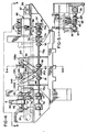
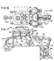
- Figures 1, 2 and 6 show, respectively, the overall configuration of a press in accordance with a preferred embodiment of the invention, and the general arrangement of the progressive tooling to work upon shells, form completed tabs from a strip of material, and attach these tabs to complete the manufacture or conversion of the shells into ends for cans and similar containers.
- the press illustrated in Figures 1, 2 and 3 is typical of a 45 ton single acting press, and includes a bed 10, side frames including uprights 12, 13, 14 and 15 surrounding side openings 16 and 17, and a crown 18 supported on the side frames.
- the crank 20 is rotatably supported in the crown, and has secured to it a flywheel 22, and is belt-driven by a drive motor 25 supported on top of the crown structure.
- the crank is connected to the slide 30 by a pair of connecting rods (not shown), and in conventional fashion cooperative upper and lower tooling sets indicated by the general reference numerals 35 and 36, are mounted on the slide and on the bed respectively.
- the crank 20 is fitted with a power take-off pulley 38.
- a belt 40 transfers power from the crank pulley 38 to a pulley 42 connected to drive a shaft 45 which is mounted in suitable bearings 46 supported outboard from the uprights or posts 14 and 15 which are part of the right hand side frame of the press (as viewed from the front).
- Shaft 45 is connected via a clutch 48 to a right angle intermittent drive unit 50, of conventional construction, which in turn is connected through an output clutch 52 to a shaft 53 supported in bearings 54 and carrying a drive drum 55 which is rotated in timed intermittent fashion, synchronized with the rotation of the crank 20, and therefore with the motion of the press slide 30.
- an idler drum 57 is supported in suitable bearings 58, and extending between the drums 55 and 57 is a conveyor belt 60.
- This belt is of the endless type, made preferably of material such as thin stainless steel, and is provided with two rows or paths of regularly spaced carrier openings 62. These openings are of a diameter such that the lip of a shell overlaps the edge of the openings, and thus shells deposited on the belt cover each of the openings and are carried by the belt through the tooling, in intermittent or step-wise fashion, synchronized to the operating strokes of the press.
- Shells to be converted are loaded onto belt 60 at the loading station indicated by general reference numeral 65 in Figure 3, and the shells, now converted into finished ends, are unloaded from belt 60 at the unloading station indicated by the general reference numeral 68.
- the loading and unloading mechanisms are also referred to in the art, as a down-stacker mechanism and an up-stacker mechanism, referring to the manner in which these mechanisms remove single shells from the bottom of a supply stack thereof and place a single shell onto an opening in the belt, and at the discharge location, remove the finished ends and pass them upwardly into a stack thereof.
- the power takeoff shaft 45 also is fitted with a pulley 70 that is connected via belt 72 to a further shaft 75 extending across the rear of the press bed.
- This shaft in actuality comprises several sections, the first of which 75a is supported in bearings 77 and has a pulley 78 thereon driven by belt 72.
- the pulley 79 immediately above pulley 78 is an adjustable idler for the purpose of keeping proper tension in belt 72.
- Shaft section 75a is connected through coupling 81 to the input of a right angle gear drive unit 80, and through that unit and a further coupling 82 to the shaft section 75b.
- a further coupling 84 ( Figure 4) is connected to the right angle output of gear box 80, to drive a shaft 85 which is supported in depending bearing amounts 87.
- the shaft 85 drives a pair of pulleys 88, and also drives an eccentric 90. The purpose of these driven items is explained hereafter.
- Shaft section 75b is connected by a further coupling 92 ( Figures 3 and 4) to another shaft section 75c which is supported in suitable bearings 94, and this shaft section in turn drives a final shaft section 75d through an overload friction-type clutch 95.
- the final shaft section 75d is supported in bearings 97 below and rearward of the discharge station 68, and a pulley 98 and belt 99 provide power to that station.
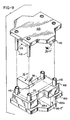
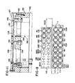
- FIGs 3, 6, 8 and 9 illustrate details of the unique upper and lower tooling sets 35, 36 which are provided in accordance with a preferred embodiment of the invention.
- the lower tooling set includes a subplate 100 upon which is secured a die shoe 102.
- the subplate is secured to the press bed by suitable fasteners (not shown) including precision locating pins in 104 and bushings 105 ( Figure 8) and are dimensioned to fit centrally between the side frames of the press, between and below the side openings 16 and 17.
- the subplate and die shoe at opposite sides have the same general rectangular end configuration, but at the center the subplate includes outwardly extending parts or extensions 100a both frontward and backward of the bed, while the die shoe is provided with niches 102a in generally corresponding locations.
- the punch holder plate 105 is fastened to the bottom surface of the slide 30 and corresponds in outline shape to the subplate 100.
- the die shoe and the punch holder plate are provided with cooperating stop blocks 108 which provide limits for the close position of the tooling (in known manner) and the punch holder plate is fitted with four guide rods 110 arranged generally near the four corners of the rectangular parts of the tooling, and extending downward into receiving posts or sockets 112 fitted to the die shoe and including suitable precision ball bearing guides (not shown) which assure the necessary high accuracy of interfit between the upper (punch) and lower (die) tooling parts.
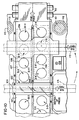
- Conventional end conversion tooling is mounted on the die shoe, defining a plurality of stations arranged in two lanes, corresponding to the lanes of conveyor 60.
- Corresponding upper or punch tooling is mounted to the underside of the punch holder plate 105, thus shells placed in the apertures of the conveyor are carried progressively to the succeeding stations of the end conversion tooling by each step-wise movement of the conveyor.
- the end converting path thus defined extends from side to side of the press and the end conversion stations are laid out on the die shoe and punch holder plate in such fashion that they are generally symmetrically disposed with respect to the side to side and front to back center lines of the press, thereby equilibrating to a considerable extent the forces not heretofore achieved on the bed and slide.
- the subplate 100 and the punch holder plate 105 are fitted with tab forming tooling 35-T and 36-T which extends transversely of the end conversion tooling, in a direction generally front to back of the press, such tab conversion tooling being divided into first and second parts each of which consists of cooperating punch and die members, and which are supported on the extensions 100a and 105a of the subplate and punch holder plate respectively. Because of the height of the tab conversion dies, these are mounted to the subplate and fitted within the niches 102a of the die shoe 102. The path defined by the tab forming tooling is located on the front-back center line of the press, thereby also equilibrating the reaction forces on the slide and bed produced by operation of the tab forming tooling.
- the end conversion tooling stations are disposed in lanes I and II and are identified as:
- Figure 7 shows, with a series of progressive views of an end from which the idle station is omitted, the conventional operations performed at those stations. Details of the individual punches and dies are not shown since these will vary with any particular installation, and they are not necessary for an understanding of the present invention.
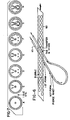
- Figure 8 shows the progressive steps in forming tabs from a strip 115 of suitable material such as aluminum, which is fed from a supply roll 116 ( Figure 2) along the tab forming path and then through the transfer/stake stations I-G and II-G.
- the tab forming tooling extends to the front and back of the end conversion tooling, as mentioned, and the completed tabs remain attached to the strip as it is looped back to the transfer/stake station (see Figures 3, 6, 10 and 19). There the tabs are removed from the strip, attached to the ends, and the remainder of the strip proceeds to scrap collection.
- details of the tab forming tooling are not shown since they will vary with the type of end being made, and they are not necessary for an understanding of the invention.
- a bridge 120 which receives the strip of partially formed tabs and carries them across the end conversion tooling into the remainder of the tab tooling located to the front side of the conveyor.
- the bridge consists of a bottom plate 121 with a front to back extending slot 122, and a cover 124 fitted to the strip and secured by suitable fasteners to its sides, whereby the slot 122 provides a closed passageway for a strip of material (later described) from which tabs are being formed.
- the stations of the end conversion tooling, along with the conveyor, define a side-to-side end conversion path
- the tab forming tooling defines a tab forming path in a front-back direction that is transverse to and crosses the end conversion path, then loops back to carry the tabs into the transfer/stake station.
- the symmetrical relationship of the tooling to the bed and slide can be observed in Figure 3, by comparing the outline of the tooling subplate 100 to the side frame uprights 12-15 within which the slide reciprocates.
- the reaction forces on the slide and bed during closing and working of the tooling are distributed in approximately uniform fashion over the area of the slide and the underlying bed. This permits maximizing the loading on the press and enables two-out production of ends in a press typically having a rated capacity of forty-five tons (U.S.).
- the die (lower) parts of the end conversion tooling are located in vacuum boxes 130, which are shown in outline form in Figure 3 and in greater detail in Figures 10 and 11.
- These comprise a lower generally rectangular frame 132 bolted to die shoe 102, and an upper frame 133 bolted to the lower frame.
- the upper frame has circular openings 134 which surround the dies, and support rails 135 are bolted to the upper frame, extending along the end conversion path and providing support, at both sides and the center, to the underside of conveyor 60.
- a top plate 137 is bolted to upper frame 133 and is provided with circular openings 138 corresponding to openings 134.
- the top plate thus also functions as a cover for the vacuum box, encloses the center and side edges of the conveyor, and the openings provide passage for the upper (punch) end conversion tools.
- the shell feeding mechanism 65 sometimes referred to as a downstacker, has been mentioned earlier with respect to its general function, and its location on the press ( Figure 3). Additional details of a suitable mechanism are shown in Figures 13, 14 and 15. This mechanism is per se known, but a brief description of it is desirable to appreciate its function in the present invention.
- the base plate 147 holds both mechanisms, and is mounted over conveyor 60, outside of the left side frame ( Figure 3).
- Above chamber 150 there is a circular feed opening 155, of a diameter just large enough to pass the shells S which descend from a stack thereof contained within three guide rods 156.
- the lowermost shell S has its lip supported on the feeding threads of three feed screws 158, spaced around opening 155 such that 360° rotation of these screws will carry the lowermost shell from the stack and deposit the shell in a belt carrier opening 62 located beneath the feed opening 155.
- the power and timing for the feed screw rotation is derived from belt 99, which is driven from power take-off shaft section 75d as earlier described.
- Belt 99 wraps over and drives pulleys 159 which are fixed to short feeder-shafts 160 that are supported in suitable bearing blocks above the base plate 147.
- Bevel gear sets 162 transfer power to vertical shafts 163 which are mounted in suitable bushing ( Figure 15) in circular top plates 164.
- Pinions 165, on the shafts 163, mesh with internal gears 167, and pinions 168 on the feed screws 158 are driven from the internal gears through idler gears 169.
- the intermittent rotation of the shaft 75 is translated into 360° rotations of feed screws 158, and a single shell is deposited in a carrier opening 62 as those openings halt under the feed opening 155.
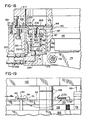
- the first power takeoff shaft 75a has an eccentric or cam 170 thereon ( Figures 3 & 17) which is coupled to oscillate a rod 171.
- the end of rod 171 is pinned to a rocker arm 172 which is supported by a bearing mounted stub shaft 173.
- the rocker arm includes a set of parallel arms 174 which straddle a piston carrier block 175, and fasten to the block through a cross-pin 176.
- the mechanisms on the block 175 are duplicated for each unloading station in lanes I and II, hence only one mechanism is hereafter described.
- the block has a recess 178 which receives an extension 179 of a primary piston 180 that is reciprocably retained in a sleeve 182.
- This sleeve is mounted within a boss 183 on a sub-plate 185, which in turn is bolted to the lower plate 187 of the mechanism.
- An upper plate 188 is fastened to, and cooperates with, the lower plate 187 to define a passageway 190 for the upper flight of conveyor 60, on which are carried the finished ends; one of these is shown at E, being removed from the conveyor.
- the upper end of primary piston 180 extends, in its fully raised position (shown in Figures 17 and 18) into an opening 192 formed into lower plate 187 and receiving the upper edge of boss 183. In this position, however, the top of the primary piston 180 is below the conveyor passageway 190.
- the center of piston 180 has a central bore 195, an upper cavity 196 in its head, and a counterbore 197 therebetween in which is fastened a gland member 198.
- a secondary piston 200 is supported in the gland and has a lower head 201, with an O-ring seal 202, slidable in bore 195.
- a secondary head 205 is secured to the top of piston 200 by a machine screw 206, and is sized to fit within cavity 196 on top of gland member 198.
- the upper surface of head 205 is designed to engage an end E, as shown, and lift the end from the conveyor, thrusting it upward into a receiver opening 210 within the base plate 212 of the upstacker storage.
- a plurality of laterally sliding fingers 215 extend inward of opening 210, at its interface with plate 188. These fingers are urged inward by a garter spring 216, and the fingers will yield to the pressure of the flange on an upwardly thrust end E, to capture the end at the bottom of a stack thereof formed in opening 210.
- the stack of ends can rise through a corresponding opening in top plate 217, and into magazines defined by upwardly extending rods 218 ( Figures 16 and 17).
- the chamber 195 in the primary piston is connected via passages 220 to a flexible hose 222.
- the space between gland members 198 and the top of lower head 201 is connected via passages 224 to a flexible hose 225.
- Air (or other fluid) under pressure can be applied to one of these hoses and evacuated from the other, under control of a suitable valve shown schematically at 227 ( Figure 17).
- acceptable finished ends are thrust up into the stacks, while detected unacceptable ends are carried to and discharged over drum 55.
- This arrangement can readily be reversed, however, merely by having suitable fault detectors (not shown) actuate the valve 227 in the opposite fashion. In such case only rejected ends will be raised into the magazines, and acceptable ends can discharge over drum 55 into any suitable collection device.
- the tabs T are formed from a strip 115 of aluminum or like material, supplied from a roll 116 and directed along the tab forming path which is transverse to the end conversion path and generally along the transverse center line of the press (see Figures 3 and 10).
- This strip is advanced through the tab forming tooling and the bridge 120 over the conversion tooling, forms a reverse loop 230 ( Figures 2, 3 and 6), passes back through the guide 232 ( Figure 19) into the stations I-G, II-G, and the remaining scrap strip is cut into suitable pieces and discharged.
- FIGS 4 and 5 show the incremental strip feeding mechanisms 235A and 235B which are driven in incremental fashion from belts 88.
- These feeding mechanisms are identical and commercially available from Ferguson Machine Co. under the name Camtrol roll feed. Essentially, these mechanisms receive intermittent rotary input from the power take-off shaft 75, gear box 80, and belts 88, and provide intermittent rotary feed output to feed rollers 236, between which the strip 115 is threaded. Pressure adjustment devices 237 control the pressure of the rollers 236 against the strip.
- strip 115 is withdrawn from roll 116 by the mechanism 235A, passes through the tab forming tooling and transfer/stake station, and discharges through a guillotine cutter 240.
- the cutter or chopper is driven by a rocker arm 241 and connecting rod 242 which is reciprocated by a cam 243 mounted to the end of shaft 85.
- the strip 115 is thereby fed in push-pull fashion through the looped path shown in Figure 6.
- Two lanes of tabs T-I and T-II are formed in the strip, through the steps shown and noted in Figure 8. These tabs remain attached to the strip at the connection Tc, and are carried around the loop into the transfer/stake station I-G and II-G. It will be noted that center lines of the two tab lanes align with the centers ofthe ends located at the station; these centers are indicated by crosses on Figure 10.
- the rivet holes in the tabs located at this station are thus aligned with the button or rivet on the ends, and as the connections Tc are severed, the tabs are set onto the ends.
- Complete closing of the tooling finishes the attachment by staking the rivets to form the well-known integral rivet attachment between the tabs and ends.
- the end conversion is complete and the ends proceed to the unloading mechanism.
- the remainder of the strip 115 proceeds to the cutter 240, where the strip is cut into short lengths as it is fed incrementally. These scrap lengths can be suitably collected for reclaiming, in known fashion.
Landscapes
- Engineering & Computer Science (AREA)
- Mechanical Engineering (AREA)
- Press Drives And Press Lines (AREA)
Applications Claiming Priority (2)
| Application Number | Priority Date | Filing Date | Title |
|---|---|---|---|
| US06/610,446 US4568230A (en) | 1984-05-15 | 1984-05-15 | Two-out belt system |
| US610446 | 2003-06-30 |
Publications (3)
| Publication Number | Publication Date |
|---|---|
| EP0161651A2 EP0161651A2 (en) | 1985-11-21 |
| EP0161651A3 EP0161651A3 (en) | 1986-10-08 |
| EP0161651B1 true EP0161651B1 (en) | 1990-08-22 |
Family
ID=24445043
Family Applications (1)
| Application Number | Title | Priority Date | Filing Date |
|---|---|---|---|
| EP85105819A Expired - Lifetime EP0161651B1 (en) | 1984-05-15 | 1985-05-11 | Two-out belt system |
Country Status (10)
| Country | Link |
|---|---|
| US (1) | US4568230A (xx) |
| EP (1) | EP0161651B1 (xx) |
| JP (1) | JPS6156748A (xx) |
| AU (1) | AU575647B2 (xx) |
| CA (1) | CA1253401A (xx) |
| DE (1) | DE3579255D1 (xx) |
| HK (1) | HK63291A (xx) |
| NZ (1) | NZ212055A (xx) |
| SG (1) | SG58591G (xx) |
| ZA (1) | ZA853600B (xx) |
Families Citing this family (34)
| Publication number | Priority date | Publication date | Assignee | Title |
|---|---|---|---|---|
| US4762579A (en) * | 1985-12-03 | 1988-08-09 | Toyo Seikan Kaisha, Ltd. | Process for producing easily openable closure |
| US4723882A (en) * | 1986-11-25 | 1988-02-09 | The Minster Machine Company | Apparatus for forming easy-open can ends |
| US4799846A (en) * | 1986-11-25 | 1989-01-24 | The Minster Machine Co. | Transfer belt for can end conversion press |
| ES2025221B3 (es) * | 1987-02-12 | 1992-03-16 | Bruderer Ag | Prensa de estampacion |
| US4854799A (en) * | 1988-01-13 | 1989-08-08 | Service Tool Die & Mfg. Co. | Dual lane conversion system |
| ATE126108T1 (de) * | 1988-01-13 | 1995-08-15 | Service Tool Die & Mfg | Zweispurenumwandlungssystem. |
| US5182934A (en) * | 1988-01-13 | 1993-02-02 | Service Tool Die & Mfg. Co. | Dual lane conversion system |
| US5102278A (en) * | 1988-05-06 | 1992-04-07 | Service Tool Die & Mfg. Company | Press with external tooling arrangement |
| GB8816380D0 (en) * | 1988-07-15 | 1988-08-10 | Metal Box Plc | Press & transfer tool |
| US5158410A (en) * | 1990-07-26 | 1992-10-27 | Dayton Reliable Tool & Mfg. Co. | Belt and drive for conversion press |
| US5119664A (en) * | 1990-11-19 | 1992-06-09 | Dayton Reliable Tool & Mfg. Co. | All purpose integral rivet and method of forming same |
| US5224053A (en) * | 1991-01-22 | 1993-06-29 | Dayton Reliable Tool & Mfg. Co. | Interactive control for can end systems |
| US5349843A (en) * | 1992-08-06 | 1994-09-27 | Buhrke Industries, Inc. | Overhead belt discharge apparatus for container end closures |
| US6022179A (en) * | 1993-05-12 | 2000-02-08 | Artrip, Donald Jason | System and method when forming lift-tab can end assemblies |
| US7063492B1 (en) * | 1993-05-12 | 2006-06-20 | Jerry Artrip | System for forming and attaching lift-tabs to can ends |
| US20080267736A1 (en) * | 1993-05-12 | 2008-10-30 | Donald Jason Artrip | System for forming and securing lift-tabs to can ends having an elongated crank shaft |
| US7237999B1 (en) * | 1993-05-12 | 2007-07-03 | Jerry Artrip | System for forming and securing lift-tabs to can ends having two frames |
| US5660516A (en) * | 1993-05-12 | 1997-08-26 | Artrip; Donald Jason | Turning easy open can top tabs over automatically when these tabs are made up-side-down |
| US5511920A (en) * | 1993-10-14 | 1996-04-30 | Artrip; Donald | System and method for use when forming lift-tab can end assemblies |
| US5704754A (en) * | 1995-04-13 | 1998-01-06 | Eichmann; Harry | Can end fabricating system including an improved conveyor belt drum |
| US6070713A (en) * | 1995-04-13 | 2000-06-06 | Universal Die & Stampings, Inc. | Can end fabricating system including an improved conveyor belt drum |
| US5741105A (en) * | 1997-01-31 | 1998-04-21 | Dayton Systems Group, Inc. | Method of and apparatus for manufacturing tabs for easy-open can end |
| US5876171A (en) * | 1997-05-09 | 1999-03-02 | Dayton Reliable Tool & Mfg. Co. | One-out conversion press |
| EP0941779A1 (en) * | 1998-03-09 | 1999-09-15 | Battaglia Bergomi, Claudia | Stock feeding device of a press |
| EP0941830A1 (en) * | 1998-03-10 | 1999-09-15 | Battaglia Bergomi, Claudia | Device for postitioning progessively forming can ends on a forming apparatus |
| GB2347370B (en) | 1999-02-12 | 2002-10-30 | American Nat Can Co | Method and apparatus for printing |
| US6533518B1 (en) | 1999-08-31 | 2003-03-18 | Rexam Beverage Can Company | Can end manufacturing system and press therefor |
| US6695132B2 (en) * | 1999-11-24 | 2004-02-24 | Dayton Systems Group, Inc. | Conveyor system for can end conversion systems |
| KR100392979B1 (ko) * | 2001-01-13 | 2003-07-28 | 유성우 | 스틸캔 오프너의 자동정렬 및 공급장치에 적용되는에어슈트부 |
| US7305861B2 (en) * | 2004-07-13 | 2007-12-11 | Rexam Beverage Can Company | Single action press for manufacturing shells for can ends |
| EP3269469A1 (en) | 2013-03-15 | 2018-01-17 | Stolle Machinery Company, LLC | Conversion press |
| US10421111B2 (en) * | 2015-04-17 | 2019-09-24 | Ball Corporation | Method and apparatus for controlling an operation performed on a continuous sheet of material |
| EP3850298A4 (en) * | 2018-09-10 | 2022-07-20 | Ball Corporation | METHOD AND APPARATUS FOR CONTROLLING AN IMPLEMENTATION MADE ON A CONTINUOUS SHEET OF MATERIAL |
| US11433451B2 (en) * | 2019-12-12 | 2022-09-06 | Stolle Machinery Company, Llc | Conversion press and tab stock feeder assembly therefor |
Family Cites Families (10)
| Publication number | Priority date | Publication date | Assignee | Title |
|---|---|---|---|---|
| US3245370A (en) * | 1963-09-11 | 1966-04-12 | American Can Co | Apparatus for manufacturing end closures |
| US3366086A (en) * | 1965-06-18 | 1968-01-30 | Ermal C. Fraze | Method of fabricating a sheet metal joint |
| US3470837A (en) * | 1967-11-03 | 1969-10-07 | Ermal C Fraze | Apparatus for forming easy-open can ends |
| US3550546A (en) * | 1968-04-08 | 1970-12-29 | Fraze Ermal C | Apparatus for making easy-opening can ends |
| US3683834A (en) * | 1969-04-30 | 1972-08-15 | Crown Cork & Seal Co | Container forming apparatus |
| US3683665A (en) * | 1970-09-29 | 1972-08-15 | Textron Inc | Multiple station forming press |
| US4026226A (en) * | 1976-03-01 | 1977-05-31 | American Can Company | Press apparatus and method utilizing same |
| US4208976A (en) * | 1978-11-20 | 1980-06-24 | The Continental Group, Inc. | Tab applicator and bonding apparatus and method of utilizing the same |
| US4341498A (en) * | 1980-06-23 | 1982-07-27 | Aluminum Company Of America | Method and apparatus for blanking, folding and inserting membrane into container covercap |
| US4455114A (en) * | 1981-09-14 | 1984-06-19 | General Can Company, Inc. | Method for making a metallic-convenience closure |
-
1984
- 1984-05-15 US US06/610,446 patent/US4568230A/en not_active Ceased
-
1985
- 1985-05-11 EP EP85105819A patent/EP0161651B1/en not_active Expired - Lifetime
- 1985-05-11 DE DE8585105819T patent/DE3579255D1/de not_active Expired - Lifetime
- 1985-05-13 NZ NZ212055A patent/NZ212055A/en unknown
- 1985-05-13 ZA ZA853600A patent/ZA853600B/xx unknown
- 1985-05-14 CA CA000481459A patent/CA1253401A/en not_active Expired
- 1985-05-14 AU AU42471/85A patent/AU575647B2/en not_active Ceased
- 1985-05-15 JP JP60103621A patent/JPS6156748A/ja active Granted
-
1991
- 1991-07-22 SG SG585/91A patent/SG58591G/en unknown
- 1991-08-15 HK HK632/91A patent/HK63291A/xx not_active IP Right Cessation
Also Published As
| Publication number | Publication date |
|---|---|
| AU575647B2 (en) | 1988-08-04 |
| AU4247185A (en) | 1985-11-21 |
| DE3579255D1 (de) | 1990-09-27 |
| US4568230A (en) | 1986-02-04 |
| JPH0462816B2 (xx) | 1992-10-07 |
| EP0161651A3 (en) | 1986-10-08 |
| SG58591G (en) | 1991-08-23 |
| EP0161651A2 (en) | 1985-11-21 |
| CA1253401A (en) | 1989-05-02 |
| HK63291A (en) | 1991-08-23 |
| ZA853600B (en) | 1985-12-24 |
| JPS6156748A (ja) | 1986-03-22 |
| NZ212055A (en) | 1986-10-08 |
Similar Documents
| Publication | Publication Date | Title |
|---|---|---|
| EP0161651B1 (en) | Two-out belt system | |
| US4723882A (en) | Apparatus for forming easy-open can ends | |
| US4799846A (en) | Transfer belt for can end conversion press | |
| US4026226A (en) | Press apparatus and method utilizing same | |
| CA1169711A (en) | Can end making apparatus | |
| US4640116A (en) | Two-out belt system | |
| USRE33061E (en) | Two-out belt system | |
| US20070166131A1 (en) | Can end conversion system | |
| US6405853B1 (en) | Conveyor system for can end conversion systems | |
| EP1252077A1 (en) | Conveyor system for can end conversion systems | |
| US7234907B1 (en) | System for forming and securing lift-tabs to can ends having a drive belt | |
| US3889509A (en) | Horizontal can ironing press | |
| US20080267736A1 (en) | System for forming and securing lift-tabs to can ends having an elongated crank shaft | |
| CN110976628A (zh) | 一种全自动不锈钢拉环成型工艺及其成型系统 | |
| US6695132B2 (en) | Conveyor system for can end conversion systems | |
| US4166424A (en) | Press apparatus and method utilizing same | |
| US5876171A (en) | One-out conversion press | |
| US5102278A (en) | Press with external tooling arrangement | |
| CN212822306U (zh) | 一种纽扣冲压成型装置 | |
| US5182934A (en) | Dual lane conversion system | |
| CN206997605U (zh) | 笔记本风扇上盖冲压成型装置 | |
| US4854799A (en) | Dual lane conversion system | |
| US7063492B1 (en) | System for forming and attaching lift-tabs to can ends | |
| US4936729A (en) | Press with external tooling arrangement | |
| CN221434735U (zh) | 一种双层立式流水线结构 |
Legal Events
| Date | Code | Title | Description |
|---|---|---|---|
| PUAI | Public reference made under article 153(3) epc to a published international application that has entered the european phase |
Free format text: ORIGINAL CODE: 0009012 |
|
| AK | Designated contracting states |
Designated state(s): BE CH DE FR GB IT LI NL SE |
|
| PUAL | Search report despatched |
Free format text: ORIGINAL CODE: 0009013 |
|
| AK | Designated contracting states |
Kind code of ref document: A3 Designated state(s): BE CH DE FR GB IT LI NL SE |
|
| 17P | Request for examination filed |
Effective date: 19861022 |
|
| 17Q | First examination report despatched |
Effective date: 19871207 |
|
| GRAA | (expected) grant |
Free format text: ORIGINAL CODE: 0009210 |
|
| AK | Designated contracting states |
Kind code of ref document: B1 Designated state(s): BE CH DE FR GB IT LI NL SE |
|
| ITF | It: translation for a ep patent filed | ||
| REF | Corresponds to: |
Ref document number: 3579255 Country of ref document: DE Date of ref document: 19900927 |
|
| ET | Fr: translation filed | ||
| ITTA | It: last paid annual fee | ||
| PLBE | No opposition filed within time limit |
Free format text: ORIGINAL CODE: 0009261 |
|
| STAA | Information on the status of an ep patent application or granted ep patent |
Free format text: STATUS: NO OPPOSITION FILED WITHIN TIME LIMIT |
|
| 26N | No opposition filed | ||
| EAL | Se: european patent in force in sweden |
Ref document number: 85105819.8 |
|
| PGFP | Annual fee paid to national office [announced via postgrant information from national office to epo] |
Ref country code: FR Payment date: 19950510 Year of fee payment: 11 |
|
| PGFP | Annual fee paid to national office [announced via postgrant information from national office to epo] |
Ref country code: CH Payment date: 19950516 Year of fee payment: 11 |
|
| PGFP | Annual fee paid to national office [announced via postgrant information from national office to epo] |
Ref country code: SE Payment date: 19950517 Year of fee payment: 11 |
|
| PGFP | Annual fee paid to national office [announced via postgrant information from national office to epo] |
Ref country code: NL Payment date: 19950531 Year of fee payment: 11 |
|
| PGFP | Annual fee paid to national office [announced via postgrant information from national office to epo] |
Ref country code: BE Payment date: 19950712 Year of fee payment: 11 |
|
| PG25 | Lapsed in a contracting state [announced via postgrant information from national office to epo] |
Ref country code: SE Effective date: 19960512 |
|
| PG25 | Lapsed in a contracting state [announced via postgrant information from national office to epo] |
Ref country code: LI Effective date: 19960531 Ref country code: CH Effective date: 19960531 Ref country code: BE Effective date: 19960531 |
|
| BERE | Be: lapsed |
Owner name: DAYTON RELIABLE TOOL & MFG. CO. Effective date: 19960531 |
|
| PG25 | Lapsed in a contracting state [announced via postgrant information from national office to epo] |
Ref country code: NL Effective date: 19961201 |
|
| REG | Reference to a national code |
Ref country code: CH Ref legal event code: PL |
|
| PG25 | Lapsed in a contracting state [announced via postgrant information from national office to epo] |
Ref country code: FR Effective date: 19970131 |
|
| EUG | Se: european patent has lapsed |
Ref document number: 85105819.8 |
|
| NLV4 | Nl: lapsed or anulled due to non-payment of the annual fee |
Effective date: 19961201 |
|
| REG | Reference to a national code |
Ref country code: FR Ref legal event code: ST |
|
| REG | Reference to a national code |
Ref country code: GB Ref legal event code: IF02 |
|
| PGFP | Annual fee paid to national office [announced via postgrant information from national office to epo] |
Ref country code: GB Payment date: 20030401 Year of fee payment: 19 |
|
| PGFP | Annual fee paid to national office [announced via postgrant information from national office to epo] |
Ref country code: DE Payment date: 20030530 Year of fee payment: 19 |
|
| PG25 | Lapsed in a contracting state [announced via postgrant information from national office to epo] |
Ref country code: GB Free format text: LAPSE BECAUSE OF NON-PAYMENT OF DUE FEES Effective date: 20040511 |
|
| PG25 | Lapsed in a contracting state [announced via postgrant information from national office to epo] |
Ref country code: DE Free format text: LAPSE BECAUSE OF NON-PAYMENT OF DUE FEES Effective date: 20041201 |
|
| GBPC | Gb: european patent ceased through non-payment of renewal fee |
Effective date: 20040511 |