EP0160549A2 - Circuit pour produire une combinaison vidéo de plusieurs images vidéo - Google Patents
Circuit pour produire une combinaison vidéo de plusieurs images vidéo Download PDFInfo
- Publication number
- EP0160549A2 EP0160549A2 EP85302988A EP85302988A EP0160549A2 EP 0160549 A2 EP0160549 A2 EP 0160549A2 EP 85302988 A EP85302988 A EP 85302988A EP 85302988 A EP85302988 A EP 85302988A EP 0160549 A2 EP0160549 A2 EP 0160549A2
- Authority
- EP
- European Patent Office
- Prior art keywords
- video
- video image
- key
- digital
- signals
- Prior art date
- Legal status (The legal status is an assumption and is not a legal conclusion. Google has not performed a legal analysis and makes no representation as to the accuracy of the status listed.)
- Granted
Links
- 230000004044 response Effects 0.000 claims abstract description 24
- 239000002131 composite material Substances 0.000 claims description 50
- 238000000034 method Methods 0.000 claims description 32
- 239000013598 vector Substances 0.000 claims description 12
- 230000002123 temporal effect Effects 0.000 claims description 10
- 230000009467 reduction Effects 0.000 claims description 7
- 238000004519 manufacturing process Methods 0.000 claims description 4
- 230000008569 process Effects 0.000 description 23
- 230000000694 effects Effects 0.000 description 20
- 230000009977 dual effect Effects 0.000 description 16
- 230000001934 delay Effects 0.000 description 9
- 230000033001 locomotion Effects 0.000 description 6
- 238000000926 separation method Methods 0.000 description 5
- 230000001360 synchronised effect Effects 0.000 description 5
- 239000000872 buffer Substances 0.000 description 4
- 230000008859 change Effects 0.000 description 4
- 238000010586 diagram Methods 0.000 description 4
- 238000004364 calculation method Methods 0.000 description 2
- 230000003111 delayed effect Effects 0.000 description 2
- 230000007704 transition Effects 0.000 description 2
- 230000000007 visual effect Effects 0.000 description 2
- 240000005020 Acaciella glauca Species 0.000 description 1
- 101100385390 Caenorhabditis elegans kin-3 gene Proteins 0.000 description 1
- 238000009825 accumulation Methods 0.000 description 1
- 230000008901 benefit Effects 0.000 description 1
- 238000006243 chemical reaction Methods 0.000 description 1
- 230000000295 complement effect Effects 0.000 description 1
- 230000007423 decrease Effects 0.000 description 1
- 230000003247 decreasing effect Effects 0.000 description 1
- 230000001419 dependent effect Effects 0.000 description 1
- 238000005286 illumination Methods 0.000 description 1
- 235000003499 redwood Nutrition 0.000 description 1
- 230000026676 system process Effects 0.000 description 1
Images


Classifications
-
- H—ELECTRICITY
- H04—ELECTRIC COMMUNICATION TECHNIQUE
- H04N—PICTORIAL COMMUNICATION, e.g. TELEVISION
- H04N5/00—Details of television systems
- H04N5/222—Studio circuitry; Studio devices; Studio equipment
- H04N5/262—Studio circuits, e.g. for mixing, switching-over, change of character of image, other special effects ; Cameras specially adapted for the electronic generation of special effects
- H04N5/272—Means for inserting a foreground image in a background image, i.e. inlay, outlay
Definitions
- the invention relates to the generation of special video effects and particularly to systems for combining selected percentages of multiple video images into a composite image, as determined by respective key signals.
- Typical of such apparatus are analog and/or digital schemes for providing a dissolve video output signal wherein, for example, an attenuator network controlled by a counter incrementally changes the signal level of one video input in one direction from a first of opposite level limits while incrementally changing the signal level of a second video input in a corresponding manner, but in the opposite direction from the other of the opposite level limits.
- Such a scheme provides a uniformly conducted dissolve operation, wherein first video information is replaced by second video information, while a summation of the varying percentage of each of the two video signals ideally always is equal to 100% over the entire dissolve interval.
- the attenuation signal in such a scheme is operated at a clock rate corresponding to the video field rate, that is, at a rate of one times or a sub-multiple of the vertical sync rate.
- a digitally controlled lap dissolver network is illustrated, by way of example, in U.S. Patent No. 3,598,908, assigned to the same assignee as is this application.
- Video signals such as generated by cameras in real time, or by recorders in non-real time, are variously combined, moved and/or otherwise selectively manipulated in such switcher apparatus.
- the switcher employs control signals commonly termed chroma key signals which, for example, are used to cut a hole in a background video signal, which hole then is filled with a foreground video signal to provide a composite video image of the two signals.
- chroma key signals which, for example, are used to cut a hole in a background video signal, which hole then is filled with a foreground video signal to provide a composite video image of the two signals.
- the combined image is formed of portions of either one or the other video signal; that is, switchers generally are capable of handling only foreground and background signals.
- the video lap dissolver type of apparatus briefly discussed above, provides simple ramp switching of two video signals, wherein the video signals themselves are gradually switched to replace one with the other.
- the production switchers of previous mention perform a switching operation on the video signals themselves, or on the video paths thereof, in the course of performing a soft or hard switch between the various incoming signals.
- the above switching techniques in general perform the switching operation in the analog domain and/or perform hard digital switching wherein inputs are either off or on.
- prior techniques of combining video signals or images suffer from the problem that stepping motions are visible in the picture during movement of the images, and further that aliasing components become apparent in regions of hard edge transitions. Additionally, such schemes generally do not afford the requisite degree of control repeatability and accuracy presently required in the field of digital special effects.
- the present invention combination adds yet a further level of sophistication to existing special effects systems.
- the present combiner contemplates an additional manipulation of multiple video images utilizing a video effect or technique known as video channel combine.
- a "combine” is effected by combining two or more channels of video signals in such a way as to make scenes or images corresponding to the various signals, appear to be one behind the other.
- a combine may display a first video image from one channel in front, followed by a second video image from a second channel, which in turn is in front of and followed by a third video image from a third channel, etc.
- the combine may appear over a selected background such as black or gray, wherein the background fills all display areas where the proportions of the composite video image do not add up to 100%.
- the video -images of the various channels in a combine may exhibit various degrees of transparency. This allows images with lower priorities, that is, images which would be hidden behind another image, to partially show through; i.e., to be partially visible due to the transparency of the image or images in front.
- the images of any channel also can be dimmed if desired, to the black, gray or other desired background.
- the dimming effect is enhanced by a light source feature which highlights selected images or planes while dimming others.
- the determination of the transparency and dimness of the channels like the changes in priority of the channels, can be programmed to occur automatically, and is made on a video field-to-field basis.
- the present combiner overcomes various shortcomings in the art discussed above, while providing various combine effects heretofore unavailable in the art. Because timing differences between video channels are completely eliminated, combines produced by the present combiner synchronize together perfectly. Multiple images of more than just a background video signal and a foreground video signal are smoothly combined with a high degree of control repeatability and accuracy. In addition to providing extensive ranges of transparency and intensity, soft edge keying with a minimum of aliasing is accommodated if a soft key is introduced by the signal system. The processes of designating priority, transparency and dimness are more readily achieved by the present combiner, since the system processes the controlling key signals, rather than processing the video images themselves as heretofore commonly done in the art.
- a combiner employing at least four channels can produce two independent combines simultaneously, with each combine being the result of combining two video images from two channels. Any one of the four channels may be selected for combination with any other channel to provide a combine. Each combine process is controlled by one of two different user control panels, while each combine utilizes different pairs of video images of the four video channels.
- video channel combines are produced by digitally processing binary numbers representing values of video image information in a channel for picture elements of a display.
- Channels to be combined are first synchronized so that binary numbers representing image values in different channels, arrive at processing logic in the combiner during the same cycle of processing clocks.
- the binary numbers are combined to produce new binary numbers which represent a combined or composite video image value to be displayed at the same temporal and spatial location of the display of the composite video image.
- Numbers are combined in the course of processing, by taking a preselected percentage of each number's value and adding the products thereof. Total percentages.resulting from the summation of all numbers for each composite video image value, including the number corresponding to the percentage of background desired, is equal to 100'.
- two or more channels of digital video are supplied directly to cutter means by a signal system.
- the cutter means perform the process of reducing (i.e., "cutting") the binary numbers of previous mention, to some percentage of their original value.
- Each respective channel also supplies associated boundary key data to respective keyer means which, in turn, supply respective processed key signals indicative of the percentage that the binary numbers of each channel are to be cut.
- the processed key signals are coupled to the respective cutter means of previous mention.
- the multiple channels of cut video signals are fed from the cutter means to adder means.
- the adder means perform a summation, or summations, of the cut video signals and supply one or more outputs therefrom.
- the outputs correspond to the composite video images formed by one or more combines, processed in accordance with the invention combination.
- the composite video images are supplied back to the signal system for conversion to a conventional analog composite video signal.
- the signal system may comprise the ADO system of previous mention.
- the present combiner provides for precisely combining a plurality of video images manipulated by the signal system with a selected background. Further, the combiner provides the channel combines without switching the major video paths, or the video signals themselves, as is commonly performed by the prior art signal combining schemes discussed above. In a system having at least four channels, the combiner provides the generation of at least two independent combines simultaneously, employing any combination of two of the four available channels under control of two separate control panels. Thus two independent users may perform independent combines simultaneously, wherein the combines need not be timed to the same reference. In a further feature, a process for automatically determining the priority of the channels, and thus the order of the video images in a combine, on a field-by-field basis, is employed to continuously determine in real time which channel or channels are in front of the other.
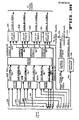
- FIGURES lA,lB An embodiment of the present combiner is illustrated in FIGURES lA,lB as a multiple channel apparatus formed of channels A, B, C and N, each carrying respective input video signals A, B, C and N supplied by an associated signal system such as the ADO system of previous mention.
- Lach channel video signal of the channels A-N also includes within the signal, respective boundary key data associated with each video image of the respective signals and supplied by the signal system. Boundary key is used herein in the usual context employed in the switcher art, as defining the presence or absence of video information in a channel; that is, it defines the boundary or border enclosing a video image displayed as a composite video image on background video.
- the boundary key data are selectively processed in the present combiner system to provide a like number of processed key signals, one and preferably two processed background key signals, and at least one and preferably two processed composite key signals.
- Processed key signals differ from the boundary key signals in that they define the percentage that the video images of respective channels are to be reduced.
- the processed key signals are defined as follows:
- FIGURE 3 illustrates a combine with scene B in front followed by scene A, which is followed by scene D, i.e., channel B is assigned the highest priority for furnishing video image information to the displayed composite video image, channel A is aligned the next highest priority and channel D the lowest priority.
- This combine of three video channels appears over gray background video, although any color of background video can be supplied.
- the channels in a combine can have various degrees of transparency. This feature allows scenes in a combine which are behind other scenes to partially show through, as depicted by the scenes in channels A and D showing through the scene in channel B. In another feature, channels also can be dimmed, an effect provided when a percentage of background video will be forced into the video in a channel.
- the combiner system is implemented by identical processing modules for each key signal input and by the associated switching, wherein a cascade output of a higher priority module is fed to the cascade input of a next lower priority module.
- the processed key signals and processed background key signals are utilized to modify the video image values in each of the channels in parallel, on a input video sample-by-video sample basis, in a digital implementation.
- a plurality of channel input/output interfaces receive channel A, B, C, N video signals, respectively, which include associated boundary key data, and also receive respective channel A, B, C, N line reference signals, from a suitable signal system.
- the channel video and line reference signals may be supplied, for example, by the ADO signal system of previous mention, within which environment the present combiner is depicted for purposes of description only. Other video sources such as, for example, video cameras may be used to supply the video and line reference signals.
- the data from the signal system is organized in a known format of combined luminance, chrominance and boundary key samples, which format enables the luminance, chrominance and key samples to be distinguished for separation.
- the I/O interfaces receive the combined samples, identifies them and provides separation thereof.
- the I/O interfaces 20-26 provide respective channel A, B, C, N, input video signals on video busses 28, 30, 32, and 34 respectively, and also provide channel A, B, C, N, boundary key signals on busses 36, 38, 40, 42 respectively. It is understood that the notation “N" representing the fourth channel indicates in conventional fashion that further channels may be added to the combiner system.
- the boundary key signals on busses 36 and 38 are coupled to keyer means 200, and the boundary key signals on busses 40, 42 are coupled to keyer means 300.
- Each keyer means generate processed key data for each channel which reflect each priority of the channels involved in a common combine.
- the keyer means also generate processed background key signals and processed composite key signals, while further supplying background video signals for each of two possible combines.
- key signals and “video signals” will hereinafter ⁇ tl 60549 referred to simply as "key” and "video” respectively.
- the channel A,B input video on busses 28 and 30 are coupled to cutter means 400, while the channel C, N input video on busses 32 and 34 are coupled to cutter means 402.
- the cutter means perform the process of reducing the digital numbers representing respective values of input samples of video image information to be displayed at the same temporal and spatial location of the display of the composite video image, to some percentage of each samples original value.
- the channel A, B processed keys are supplied by the keyer means 200 to the cutter means 400 on respective busses 44, 46, while the channel C, N processed keys are supplied by the keyer means 300 to the cutter means 402 via respective busses 48, 50.
- a background video and a processed background key generated by keyer means 200 are coupled via respective busses 52, 54 to cutter means 404, while a background video and a processed background key generated by the keyer means 300, are coupled to the cutter means 404 via the busses 56, 58 respectively.
- Composite keys generated by respective keyer means 200, 300 are supplied by busses 60, 62 to a plurality of I/O interfaces 64, 66, 68 and 70. The latter I/O interfaces are, in practice, the same I/O interfaces as those labeled 20-26 of previous mention and depicted at the left side of the FIGURE lA.
- the cutter means 400 supply channels A, B of cut video to adder means 500 via respective busses 72, 74.
- the cutter means 402 similarly provide channels C,N of cut video to the adder means 500 via busses 76 and 78.
- Cutter means 404 provide two channels of cut background video on busses 80, 82 to the adder means 500.
- the adder means include circuits for performing two independent summations, that is, combine operations, simultaneously. Any combination of inputs can be fed to either adder means circuit, and either output can be fed to any of the four channel outputs.
- the four composite video channels A, B, C, N are depicted as supplying the respective I/O interfaces 64, 66, 68, 70 respectively, via composite video busses 84, 86, 88 and 90.
- Timing reference signals are depicted extending between the I/O interfaces 20-26 and clock means 600 via lines 92.
- the clock means provide timing signals derived from the timing reference signals to all combiner system boards; viz, the keyer means, the cutter means, and the adder means circuitry via lines 94.
- control data is supplied from control units, such as operator controlled panels (not shown) of the signal system, to combiner computer means 98, via lines 96.
- the computer means 98 provide control data via multiple lines 100 to the combiner system boards formed of the various keyer and adder means and further described below.
- the present combiner employing a digital component signal television system wherein the chrominance information is described by two components in the known R-Y, B-Y format.
- the luminance component is sampled at a rate of 13.5 megaHertz (MHz) to obtain samples of the luminance information in correspondence with the known 4:1:1 digital component color television standard.
- Each of the two chrominance components is sampled and the key data are provided at a rate of one-quarter and one-half, respectively, of the 13.5 MHz rate.
- the present combiner system can readily be used with a composite signal television system wherein the composite video signal is sampled at the 13.5 MHz rate.
- the sampled luminance component is represented as an 8-bit binary number.
- the most significant bit is the sign bit, with 0 and 1 representing positive and negative signs, respectively.
- the highest value the bits can represent is 01111111, which is equivalent to +127 to the base 10.
- the lowest value is'10000000, which in twos complement form is equivalent to -128 to the base 10.
- Chrominance and key values also are represented as 8-bit binary numbers with the values ranging from -128 to +127 in the same manner as described for luminance values.
- Transparency of a channel also is represented by 8-bit binary numbers which are used to modify the boundary key data in an inverse function. That is, the higher the value of the key number, the less transparent is the channel. When the key number is a minimum value, -128, the channel is completely transparent.
- the highest number, +127 represents a complete opaque channel. It follows that a binary number having a value between the lowest and the highest number represents a corresponding partially transparent channel.
- the ADO signal system providing the video information to be processed by the combiner furnishes the video component signals and the boundary key signals organized in a known format and bandwidth compatible with the combiner. More specifically, the ADO signal system associated with each channel of the combiner provides two byte serialized stream of data in binary notation, one containing luminance data samples and the other containing alternating chrominance and boundary key data samples.
- the chrominance and boundary key data stream is in a format that permits the boundary key data samples to be distinguished and separated from the chrominance data samples.
- Each pair of byte serialized streams of luminance, chrominance and boundary key data samples from a signal system is coupled to one of the channel I/O interfaces, 20-26, which effects the separation of the video component and boundary key data samples into the required channel format.
- each I/O interface 60549 includes suitable formatting logic for effecting such identification and separation.
- the I/O interface of each channel formats the received serialized stream of data into two serialized streams, with the luminance and chrominance samples in one byte (8-bit binary number) serialized video information stream and the boundary key samples in a second byte serialized key information stream.
- each of the input video busses 28-34 and input boundary key busses 36-42 are composed of eight lines. Lines carrying luminance and chrominance data have a byte period of 50 ns. The lines carrying key data have a byte period of 150 ns. Accordingly, by way of example only, two bytes of luminance, one of chrominance, and one of key data samples are received via each of the I/O interfaces 20-26 during 150 ns periods.
- bytes of processed key data such as received via busses 44-50, have a period of 150 ns.
- the video signal input received on busses 28-34 have a period of 50 ns. Consequently, two bytes of luminance are received for one byte of processed key data.
- Each byte of processed key data is used to cut one byte of luminance.
- One half of each byte of key data is also combined with one half of the following key byte to cut another byte of luminance.
- Chrominance bytes are functionally grouped in pairs, with each pair defining R-Y and B-Y for the same 300 ns period. Since the chrominance pair represent the same time period, they are cut with the same processed key.
- a percentage of each byte, in a group of four key bytes, is summed to produce a combined key for each functional pair of chrominance bytes.
- the two latest bytes in each group of four key bytes become the two earliest bytes in the next group of four key bytes.
- video channel combines are produced by processing the binary numbers representing image values to be displayed on a sample-by-sample basis.
- the channels to be combined first are synchronized so that binary numbers in different channels arrive at the processing logic in the combiner system during the same cycle of processing clocks. Delays in cables and equipment which cause the accumulation of small timing differences makes channel synchronization necessary, even though all video channels initially are generated in synchronism with a master reference. Synchronization is accomplished by selecting one video channel as a reference, and then synchronizing the other video channels in the same combine to the timing signals used in the reference video channel.
- the line reference signals shown coupled to the 1/0 interfaces 20-26 in FIGURE 1A provide the timing signals by which the video channels are synchronized.
- the keyer means 200,300 of FIGURE 1A are in practice interconnected to form an integral keyer unit. As depicted, keyer means 200,300 receives the boundary key of each channel A-N, but does not receive any input video from the channels. The keyer means produces the processed key which reflects the priority of each channel in a combine. The keyer means also provides one or more background video, one or more processed background keys and one or more processed composite keys as required for one or more combines respectively. Background video do not have line or vertical sync pulses and are generated as by a programmable color matte generator to provide a flat field of gray, black, or other color. Accordingly, background video may be supplied by any suitable external source.
- the background video After being cut by the background keys and added to associated combine data, the background video provide the desired background for the composite video signal, that is, the composite video image.
- Composite keys provided by the keyer means are fed to the 1/0 interfaces 64-70 of FIGURE 1B, and are utilized by downstream switcher apparatus to key in a desired different background as may be desired.
- the data representing a key for a given channel is modified by data from any channel with higher priority. For example, in a combine with channel D having the highest priority, followed by channel B and then channel C, channel D key data are uneffected. Channel B key data are modified only by key data from channel D, and channel C key data are modified by key data from both channels D and B.
- the cutter means 400, 402, 404 cuts away video that is not to appear in a combine.
- the cutter means receive the plurality of video and processed key inputs, and cuts the video in response to the respective processed keys by multiplying the processed key against the respective video, to produce cut video signals on each channel A-N.
- the cutter means is interfaced with the combiner computer means 98 via the lines 100, as further described below.
- each point 1 through 5 in FIGURE 3 represents such a location where point 1 is on the background.
- the numbers of all three channels A,B,D are cut 0% at this point since the key will be the minimum value of 10000000.
- 100% of the channel A number is added to 0% of the channel B and D numbers.
- the channel B number is cut slightly and the channel A and D numbers are cut to 0%. If a key of 01011111 is assumed for channel B, its number is cut to 87.5% at point 3.
- the position of the channel that is, the priority, in the front-to-back sequence of channels in a combine, also affects how a number is cut.
- Channel B has the highest priority
- channel A is next
- channel D has the lowest priority.
- channel D at point 4 is cut to 0% since it has a lower priority than channel A, which is completely opaque with a key of 01111111 at this point.
- the channel A number at point 5 is cut to 12.5% since it has a lower priority than channel B, which has the key of 01011111 at point 5, representing a cut to 87.5%.
- Cutting is accomplished by first processing key data according to priority and then multiplying bytes of processed key data by bytes of corresponding luminance and chrominance component data.
- binary numbers representing key are first converted to binary fractions to make them compatible with integrated circuits that perform the arithmetic functions.
- the maximum value of a number is one, written as 1.0000000, and the minimum value is zero, written as 0.0000000.
- the cut video signals are supplied to the adder means 500 which, in the embodiment of FIGURE 2B, perform two combine operations simultaneously. Any combination of video inputs can be fed to either adding process, and the outputs of either adding process can be fed to any of the channel composite video busses 84-90. Gating the video signals into and out of the adder means 500, and the gating of the 1/0 interfaces to direct video to the signal system, is controlled by the control data on lines 100 extending from the combiner computer means 98.
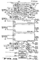
- FIGURES 2A,2B the combiner of FIGURE lA,lB is implemented as a four channel system including four channels A, B, C, D, of boundary keys, and four channels A, B, C, D, of input video, and adapted to perform two independent combines simultaneously.
- like components are similarly numbered.
- additional channels and additional combine processes are contemplated within the invention combination.
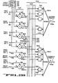
- keyer means 202 For simplicity of description, since the components in the channels A-D of keyer means 200, 300 (hereinafter termed keyer means 202) are identical, primarily the channel A circuit is discussed in detail. Thus, keyer unit 204 is described in detail, while keyer units 206, 208, 210 of channels B, C, D, respectively, are shown in block form.
- the boundary key-A on buss 36 comprises the values of the binary numbers which define the display of a video image on a given background.
- the boundary key A which may be supplied by the ADO system of previous mention (not shown), is a boundary key of selected sample rate with a given format acceptable to the present combiner system.
- the boundary key A may be generated by other sources which provide similar signals.
- the boundary key is binary numbers of 8 bits which equal 1.0 where the video image is present and is 0.0 where the image is not present, i.e., where there is background. In the transition between the image, or images, and background, the values of the key range over corresponding values between 0.0 and 1.0.
- the boundary key A is supplied to a transparency multiplier 212, which controls the transparency of the channel by modifying the key data directly in response to a computer control signal on a control line 214.
- the control signal is in the form of a transparency factor, or coefficient, supplied by the lines 100 of the computer means 98 (FIGURE 1B) which directs the multiplier 212 to multiply boundary key data by the coefficient to provide a key which is reduced by the amount of the coefficient. For example, if the coefficient equals 1, there is no effect on the boundary key A. If the coefficient is some value less than 1, the multiplier 212 reduces the value of the key accordingly.
- the coefficient key reduction for transparency effects may be changed on a field-by-field basis.
- the boundary key A after transparency, is introduced to a programmable time delay 216, which corrects the timing of the key for subsequent introduction to the key processing logic, vis, into a priority processor 218.
- the extent of the delay is programmed by the computer means 98 via lines 100 corresponding to a control input 220 of the variable delay 216.
- boundary keys for all channels are synchronized prior to entering the keyer units, they must be re- timed so that, depending upon the priority order of the channels, corresponding key data in different channels are processed by respective keyer units in the same cycle of processing clocks.
- the priority order is controlled by the computer means 98 and accordingly the delay control signal will reflect the priority of the channels. A highest priority channel will receive the shortest delay whereas the lowest priority channel will receive the longest delay.
- the time delay of the highest priority channel is zero, with increasing time delays programmed for the delays in the channels of decreasing priority order.
- the overall time delays of all channels also must be identical. Accordingly, as the computer means 98 changes the priorities of the channels on a field-to-field basis, it also alters all the channel delays to reflect the change in the priorities.
- the boundary key A from delay 2 16 thus is essentially the same signal as the boundary key A on buss 36 except for any reduction which may have been made in channel transparency.
- the key A from the delay 216 is introduced on a buss 224 as a "key-requested" output, to the priority processor 218 and particularly to a minimum circuit 222 thereof.
- the priority processor 218 also receives an input on a buss 226 from a dual selector 228.
- the selector has first and second halves and each selects one of (N+l) inputs for output therefrom in response to a common control 229 for both halves, which extends to the lines 100 of the computer means 98.
- the key on 226 is labeled "key-taken-prior" and is the resource, or key value, which has been taken by any higher priority channel.
- the key-taken-prior is fed to an inverter 230 which performs a binary inversion and generates a key on a buss 232 herein labeled "key-available”.
- the minimum circuit 222 provides an output which is the minimum value of the key-available and the key-requested outputs on busses 232, 224, respectively.
- the output on a buss 234 is labeled "key-taken", and is, in essence, the processed key for channel A.
- the minimum circuit 222 is employed for two reasons: First, under the condition for a particular image, where the key has not been reduced and channel A would like to take a selected amount of the key resource. The resource can be taken since none was taken previously. That is, channel A can have all the resource it wants as long as the key available is equal to or greater than the value wanted. Second, the channel wants a given amount of the key resource, but the key available is zero. In this case the channel can have only so much of the resource as is available; viz, none.
- the minimum circuit 222 performs a straightforward minimum value select, and includes a comparator, which compares the inputs to determine which is less, and a selector which then selects the smaller of the inputs.
- the key-taken output on buss 234 is the channel A key, which is then fed to a dimness multiplier 236, similar in function to the transparency multiplier 212 of previous discussion, except that the channel is dimmed, that is, a percentage of background video will be forced into the channel video.
- the dimness multiplier 236 is in the combiner system because, once the key-taken output on buss 234 is generated for the channel, there is no possibility of reducing the key value, since any reduction would reflect erroneously on lower priority channels which receive this output. However, there are instances in which it is desirable to reduce the value, i.e., dim the processed key of a channel.
- the dimness multiplier 236 allows the present combiner to alter the key-taken output to a smaller value, in response to a dimness factor or coefficient supplied at a control input 238 thereof, from the lines 100 of the computer means 98 of FIGURE 1B.
- a dimness factor or coefficient supplied at a control input 238 thereof from the lines 100 of the computer means 98 of FIGURE 1B.
- the transparency multiplier 212 if a coefficient of 1 is provided by the computer means 98 on control line 238, there is no reduction in the key-taken output.
- the full value is passed to a buss 240 as the processed key for the channel A, after dimming. If a smaller coefficient is supplied by the computer, then a proportionate amount of reduction in the key-taken output is provided by the dimness multiplier 236, which is reflected in the value of the processed key on buss 240.
- the processed key on buss 240 is fed to another programmable time delay 242 similar to delay 216 of previous mention.
- the second delay 242 re-times the processed key according to the delay required for the particular channel in order to supply the processed key at the subsequent cutter means of FIGURE 2B to allow it to be multiplied against the respective video in the cutter means. It follows, all processed keys must be timed with each other.
- the time delay of the delay 242 is the inverse of the amount of time provided by the delay 216.
- the overall delay of each channel that is, the amount of time delay between the input to the first delay (216) and the output of the second delay (242) through the key processing paths of each of the channels A-D, must be identical.
- the time of delay is programmed via the control line 244 coupled to the lines 100 of the computer means 98.
- the key-taken output on buss 234 and the key-taken-prior output on the buss 226, are supplied to an adder 246 which sums the resources and provides a "key-taken-now" output on a buss 248.
- the key-taken-now is the combination of the resource that was taken by any higher priority channels, and that taken by channel A.
- the key-taken-now output is coupled to a buss 250 of a pair of busses, which extend through all the keyer units of all the channels A-D, as well as through the background key channels.
- the buss 250 thus is coupled back to the input of the first section of the dual selector 228 which, in turn, provides the key-taken-prior of previous mention on buss 226.
- buss 250 also inputs to the first sections of the dual selectors of the other channel keyer units 206, 208 and 210.
- the buss 250 also is coupled to a dual selector 252 of a background key-1 channel, and to a first section of a dual selector 254 of a background key-2 channel.
- a second buss 256 also extends across the keyer units, and is coupled to the second sections of the dual selectors 252, 254 of the first and second background key channels, as well as to the second sections of the dual selectors of the video channels B-D, respectively.
- the separate busses 250,256 may comprise a single, multiplexed buss, if desired.
- the key-taken-now output on buss 248 and buss 250 is available for the next lower priority channel to select via the respective dual selector of that channel.
- channel B is the next lower priority channel
- its dual selector 257 will select the key-taken-now from channel A as its input on a buss 258 and will feed it to its priority processor 259 under a computer command extending to control line 261.
- the subsequent key-taken-prior output fed to next lower priority channel B in this example, reflects the value of the key resource taken by the higher priority channel A previously.
- the second section of the channel A dual selector 228 is coupled to the buss 256 and operates simultaneously with the first section, to provide a key-taken-prior output on a buss 260, coupled to one input of a dimness adder 262.
- the other input to the adder 262 is the processed key, after dimming, on buss 240.
- the adder 262 provides means for accounting for how much of the key resource was taken by channel A after the dimming process, if any dimming was performed.
- the adder 262 provides a key-taken-now output, after dimming, which includes the dimming values of all prior channels, and which is coupled to the buss 256.
- Subsequent lower priority channels are coupled to the buss 256 in a succession determined by the priority, in response to the computer means 98, whereupon the channel with lowest priority provides an output from its dimness adder, which is the sum of all channel dimming processes.
- the final output provides an indication of how much background video is to be included in the composite video image where no video image is present, or due to the contribution of the dimming process in regions where video images are present.
- the two busses 250 and 256 carry key resource data which indicate, respectively, how much key resource has been taken by any higher priority channels, and how much key resource has been taken after dimming processes have been added in as well.
- the busses 250, 256 also are coupled to respective 8 bit busses 266 and 268, whereby each buss 250, 256 has one more set of 8 lines than there are number of channels in the system.
- a binary x D" is inserted on busses 250, 256 via the busses 266, 268, since the highest priority channel must select a "0" input for its key-taken-prior output on buss 226, since no amount of the key resource has been taken prior to the highest priority channel.
- the computer means 98 programs the highest priority channel dual selector to select the "0" off the busses 250, 256.
- Both the key-taken-prior busses 226, 260 thus are supplied with binary "0", which inputs respectively are fed to the priority processor 218 and the dimness adder 262.
- the lowest priority channel determines the final value of the dimness reduction and supplies the number to the buss 256.
- the computer means 98 then enables the dual selector 252 or 254 of the background key channel corresponding to the associated combine process.
- the key-taken-now output indicative of the sum of the key resources after all dimming processes, is fed via the dual selector 252 or 254 to an inverter 270 or 272.
- the inverter provides an output which is one minus the inputs, i.e., 1- the total dimness sum.
- the resulting processed background key from inverter 270 or 272 is fed to a programmable time delay 274 or 278 respectively, wherein the key is suitably delayed to provide proper timing for the subsequent multiplication process in the cutter means.
- the total time delay through the processed key channels and either of the background key 1 or 2 channels must be identical.
- the suitably timed processed background keys 1 and 2 are provided on the busses 54, 58, respectively.
- the processed background keys provide data which determine how much background should be included in the composite image to compensate for dimming performed in the respective channels. Thus, if dimming in a channel is requested back to background level, as when it is desired to reduce luminance and chrominance to zero, the resulting hole in the composite video image of that channel will be filled with background.
- the output of the priority processor and of the dimming multiplier will be identical. Accordingly, the background key fills background in all areas of the video picture which are not occupied by the combined video images from the channels.
- the second sections of the dual selectors 252, 254 of the background key channels are used to provide the composite keys 1 and 2 on busses 60, 62, respectively.
- the outputs of the channel priority processors are supplied via the respective buss (248) and adder (246) of the lowest priority channel, to the buss 250 as a key-taken-now output, which data is indicative of how much key resource has been taken by all of the channels in a specific combine.
- the second section of the respective dual selectors 252 or 254 are enabled by the computer means 98 depending upon the combine, to pass the key-taken-now output from buss 250 to a respective programmable time delay of delays 276, 280, and then to busses 60 or 62.
- the processed composite keys differ from the processed background keys in that the former do not have any contribution due to the dimming process.
- the composite key is employed downstream of the present combiner as, for example, by a downstream switcher (not shown) in order to key in a different background than that provided by the combiner system.
- Background video is depicted herein on FIGURE 2A, as supplied by background video generators 282,284 on respective outputs busses 52,56 respectively.
- the resulting background video 1 and 2 comprise generally conventional programmable color matte, as previously mentioned.
- the four processed keys A, B, C, D, and the two processed background keys one for each combine being made simultaneously are supplied to the cutter means 400, 402, 404 (hereinafter termed cutter means 406).
- the processed keys are all timed to be in synchronism with the input video signals A-D on busses 28, 30, 32, 34, respectively.
- the processed keys associated with each input video signal are multiplied via respective multipliers 408, 410, 412 and 414.
- the processed background key 1 on buss 54 is multiplied by the background video 1 on buss 52 in a background multiplier 416, while the processed background key 2 is multiplied by the background video 2 in a background multiplier 418.
- the multipliers include bandwidth matching circuits that process the processed keys, to match the bandwidth of the key signal to the bandwidth of the video signal.
- the background video, which are multiplied against the corresponding background keys are simply the flat fields of programmable color matte.
- the cut video A-D from the multipliers 408-414, and the cut backgrounds 1 and 2 from multipliers 416, 418, are fed to respective 8-bit busses of a buss 502 which forms part of the adder means 500 of previous mention.
- Each set of 8 bit lines of video, e.g., busses 504, 506, 508, 510, are in turn coupled to respective buffer switches 516, 518, 520, 522, and thence to a first adder unit 524.
- the cut background 1 is fed from the buss 512 directly to adder unit 524,
- the same cut video busses 504, 506, 508 and 510 also are coupled respectively to buffer switches 526, 528, 530 and 532 of a second adder unit 534, while buss 514 of cut background 2 is coupled directly to adder unit 534 via a buss 533.
- the adder units 524, 534 supply two composite video output signals simultaneously on output busses 536, 538, for subsequent use by the signal system via the interfaces of FIGURES lA,lB.
- FIGURE 4 depicts a further implementation of a cutter section illustrated as plural multipliers 408-418 in FIGURE 2B.
- the processed key of, for example, channel A, delayed by the variable delay 242, FIGURE 2A, is fed via buss 44 to a tapped key delay 432.
- This delay provides simultaneous access to sequences of key bytes as required to generate the combined bytes of the key and video data format of previous mention.
- Outputs of the tapped delay 432 are fed as respective key byte sequences to luminance and chrominance key processor circuits 434, 436, which produce combined key bytes to cut luminance and chrominance bytes, respectively.
- the outputs of the key processor circuits are fed, as respective combined luminance and chrominance key bytes, through a key multiplexer 438 to a multiplier 440.
- the multiplier ; 440 also receives the luminance and chrominance input video signals herein depicted as input video A on the buss 28.
- the key multiplexer 438 supplies combined key bytes from the correct sources as required to multiply the luminance and chrominance bytes of the input video on buss 28.
- the cut video A signal from the multiplier 440 is fed, on the cutter buss 420, to the buss 504 of FIGURE 2B for subsequent application to one of the adder units 524,534.
- Each cutter section also has a timing generator 442 to provide clock and control signals required by the section components, on lines 444.
- the inputs to the timing generator 442 comprise a horizontal synchronizing pulse, H, and a high speed synchronous clock, 3X, signal supplied from reference video for the respective combine being processed by the cutter section.
- FIGURE 5 depicts an implementation of adder means 500 of FIGURE 2B, wherein cut video of channels A-D and cut background 1 and 2 are fed via respective busses 420-430 to adder.units 524, 534 via adder input buffers, depicted in FIGURE 2B as buffer switches 516-522 and 526-532, and by the adder busses 502. Input-enable signals for each channel are fed to each adder unit 524, 534 from a computer interface means 540 which, in turn, is controlled via inputs thereto from the lines 100 of the computer means 98 of FIGURE 1B. Those channels to be added together at any given time are gated into the same adder by active logic states of associated enable signals.
- the adder means 500 adds any two combinations of input video channels at the same time, thereby providing two combines simultaneously.
- the output of each adder unit is fed to an associated output register 536, 538, whereby the results of either combine can be supplied from the adder means 500 of FIGURE 5, on any combination of output channels.
- a restriction imposed by software in order to protect the output circuits, is that no output channel can supply both combined video signals at the same time.
- Either output register 536, 538 gates its combined video input to any combination of output channels via busses 542, wherein the outputs are fed to downstream 1/0 interfaces depicted, for example, in FIGURES 1A,lB.
- the present combiner includes means for automatically determining the priority of the channels, and thus the spatial order of the video images in a combine, on a continuous field-by-field basis.
- the region that is in front can be determined by:
- This process is repeated to find the relationships of more than two regions as in a four-channel combiner system.
- the process is used in an automatic priority selection mode of the combiner to continuously determine in real time which channels are in front of the other.
- the channels are spatially ordered from the highest to the lowest priority.
- the data generated is used by the computer means 98 to enable respective channel dual selectors (e.g., selectors 228, 257 of channels A,B, respectively) to select the channels in the order determined by the above process on a field-to-field basis.
- the computer means simultaneously changes the respective time delays of the channels (e.g., delays 216,242 of channel A, in accordance with
- the priority changes, as previously described.
- the data corresponding to the plane equations X and Y, and the locations of the four corner points, are supplied by the digital optics signal system. It is to be understood that the priority selection also can be manually programmed, and/or a combination system employing both manual and automatic priority programming .on respective pairs of channels is contemplated.
- the dimness effect of previous description integrally includes a light source feature.for highlighting selected video images in the composite video image.
- the value of dimness is recalculated for each channel for each field. The calculation is performed in softwawre by the use of an algorithm which is designed to produce a particular desired visual effect. Many such algorithms may be used in accordance with this invention.
- the algorithm has been selected so that channels of video appear to be illuminated to a selected level of ambient light.
- a parallel light source provides parallel light in a selected direction such that illumination from this source differs based on the apparent orientation of the video image.
- a value of reflectance is also assigned to each channel to determine the percentage of incident light which is reflected.
- the above process is repeated for each channel of a common combine to obtain the corresponding value of dimness for each video image of the combine.
- the results are used by the computer means 98 (FIGURE 1B) to modify the dimness factor fed to the respective control lines of the dimness multipliers (FIGURE 2A) of each of the channels on a field-to-field basis, as previously described.
- the process is readily adapted to allow manually programming the dimness values of each channel by setting SL equal to 0%, AML equal to 100% and letting R be the programmed dimness for each channel.
- the dimness value has two major components, the ambient light level AML and the parallel source light level SL.
- the parallel light level is applied to the dimness depending on the relative direction of orientation of the plane, i.e., the video image for a channel, as compared to the designated direction of the light source. This is determined by the dot product PN LSV which is equal to the magnitude of vector PN, multiplied by the magnitude of the vector LSV, multiplied by the cosine of the angle between the vectors.
- both vectors are treated as unit vectors so that the product is equal to the cosine of the angle between the vectors.
- the cosine is one and the full amount of the parallel source light level is applied to the dimness function. If the plane of the video image is parallel to the light source vector so that the angle between the light source vector and normal vector is 90°, the cosine is zero and the parallel source light level has no effect on dimness for that channel. Thus, if a video image were in an apparent rotation, the dimness resulting from the parallel light source alternately increases and decreases with changes in orientation of the video image.
- the ambient light level AML is not dependent on angle. Thus, a selected ambient light level is applied equally to all channels regardless of orientation. Accordingly, for a video image in apparent rotation, the ambient light level does not change.
- the light level incident thereon varies with the change in angle between the light source vector and a normal to the plane of the video image.
- the minimum possible light level is equal to the ambient light level and a maximum possible light level is equal to the sum of the ambient and parallel source light levels.
- Reflectance represents the percentage of incidence light which is reflected by the video image and can be individually selected for each channel. If the reflectance is at 100%, all of the light calculated for the ambient and parallel source light level will be applied to dimness. If the reflectance is zero, no light will be reflected, regardless of the ambient and parallel source light levels.
- the resulting value of dimness that is supplied in the form of a coefficient is fed to the dimness multipliers of the channels by the computer means 98, and may range from zero to 100%. Accordingly, if the calculation of the equation results in a dimness value greater than 100%, it is reduced to be equal to 100%.
Landscapes
- Engineering & Computer Science (AREA)
- Multimedia (AREA)
- Signal Processing (AREA)
- Studio Circuits (AREA)
- Signal Processing Not Specific To The Method Of Recording And Reproducing (AREA)
Applications Claiming Priority (2)
| Application Number | Priority Date | Filing Date | Title |
|---|---|---|---|
| US604790 | 1984-04-27 | ||
| US06/604,790 US4758892A (en) | 1984-04-27 | 1984-04-27 | System for producing a video combine from multiple video images |
Publications (3)
| Publication Number | Publication Date |
|---|---|
| EP0160549A2 true EP0160549A2 (fr) | 1985-11-06 |
| EP0160549A3 EP0160549A3 (en) | 1988-01-13 |
| EP0160549B1 EP0160549B1 (fr) | 1991-10-23 |
Family
ID=24421066
Family Applications (1)
| Application Number | Title | Priority Date | Filing Date |
|---|---|---|---|
| EP85302988A Expired EP0160549B1 (fr) | 1984-04-27 | 1985-04-26 | Circuit pour produire une combinaison vidéo de plusieurs images vidéo |
Country Status (4)
| Country | Link |
|---|---|
| US (1) | US4758892A (fr) |
| EP (1) | EP0160549B1 (fr) |
| JP (1) | JPH0614705B2 (fr) |
| DE (1) | DE3584465D1 (fr) |
Cited By (16)
| Publication number | Priority date | Publication date | Assignee | Title |
|---|---|---|---|---|
| WO1986006233A1 (fr) * | 1985-04-12 | 1986-10-23 | Ampex Corporation | Memoire d'image video a recirculation pour effets speciaux |
| EP0236943A2 (fr) * | 1986-03-06 | 1987-09-16 | The Grass Valley Group, Inc. | Appareil pour mélanger des signaux vidéos |
| FR2596602A1 (fr) * | 1986-03-28 | 1987-10-02 | Telediffusion Fse | Dispositif melangeur de signaux video |
| EP0260998A2 (fr) * | 1986-09-19 | 1988-03-23 | Questech Limited | Traitement de signaux d'images vidéo |
| EP0264964A2 (fr) * | 1986-10-24 | 1988-04-27 | The Grass Valley Group, Inc. | Méthode et dispositif de traitement d'un signal vidéo |
| FR2640838A1 (fr) * | 1988-12-21 | 1990-06-22 | Bosch Gmbh Robert | Dispositif de mixage de signaux video pour le traitement et la composition d'images |
| US4970595A (en) * | 1985-04-12 | 1990-11-13 | Ampex Corporation | Apparatus and method for processing video signals with key signals in accordance with previous processing of the video signals |
| US4974083A (en) * | 1985-04-12 | 1990-11-27 | Ampex Corporation | Recirculating special effects video framestore |
| US5010407A (en) * | 1987-03-27 | 1991-04-23 | Ampex Corporation | Video effects system with recirculation video combine and output combine |
| EP0473390A2 (fr) * | 1990-08-27 | 1992-03-04 | Nintendo Co. Limited | Superposition d'entités mobiles sur des images synthétiques fixes |
| EP0487267A2 (fr) * | 1990-11-17 | 1992-05-27 | Nintendo Co. Limited | Traitement d'images en couleur pour le chevauchement de parties d'image |
| EP0498647A2 (fr) * | 1991-02-11 | 1992-08-12 | Ampex Systems Corporation | Combinaison codée d'information d'images avec une véritable transparence |
| GB2256557A (en) * | 1991-05-09 | 1992-12-09 | Quantel Ltd | Television image keying systems processing |
| EP0524461A2 (fr) * | 1991-07-22 | 1993-01-27 | International Business Machines Corporation | Mélange et anti-aliasing en temps réel pour des images provenant de sources multiples |
| EP0577249A1 (fr) * | 1992-07-02 | 1994-01-05 | Ampex Systems Corporation | Architecture déterminant la priorité du mélangeur de l'enchaîné |
| CN102427511A (zh) * | 2011-09-28 | 2012-04-25 | 杭州士兰微电子股份有限公司 | 多路数字视频图像的处理方法与装置 |
Families Citing this family (39)
| Publication number | Priority date | Publication date | Assignee | Title |
|---|---|---|---|---|
| US4875097A (en) * | 1986-10-24 | 1989-10-17 | The Grass Valley Group, Inc. | Perspective processing of a video signal |
| US4991014A (en) * | 1987-02-20 | 1991-02-05 | Nec Corporation | Key signal producing apparatus for video picture composition |
| US4887159A (en) * | 1987-03-26 | 1989-12-12 | The Grass Valley Group Inc. | Shadow visual effects wipe generator |
| US4853784A (en) * | 1988-02-19 | 1989-08-01 | The Grass Valley Group, Inc. | Video switcher with independent processing of selected video signals |
| DE3925501A1 (de) * | 1988-07-30 | 1990-02-01 | Samsung Electronics Co Ltd | Mehrfachbildschirm-erzeugungsschaltkreis |
| US4873568A (en) * | 1988-09-19 | 1989-10-10 | The Grass Valley Group, Inc. | Digital video effects apparatus |
| US4947255A (en) * | 1988-09-19 | 1990-08-07 | The Grass Valley Group, Inc. | Video luminance self keyer |
| GB8822163D0 (en) * | 1988-09-21 | 1988-10-26 | Abekas Video Systems | Video signal processing |
| JPH02285393A (ja) * | 1989-04-26 | 1990-11-22 | Matsushita Electric Ind Co Ltd | 並列型マルチ動画像表示装置 |
| US4947256A (en) * | 1989-04-26 | 1990-08-07 | The Grass Valley Group, Inc. | Adaptive architecture for video effects |
| US4947254A (en) * | 1989-04-27 | 1990-08-07 | The Grass Valley Group, Inc. | Layered mix effects switcher architecture |
| DE3932757C2 (de) * | 1989-09-30 | 1998-07-23 | Philips Broadcast Television S | Verfahren und Anordnung zur Ableitung eines Stanzsignals |
| US5227863A (en) * | 1989-11-14 | 1993-07-13 | Intelligent Resources Integrated Systems, Inc. | Programmable digital video processing system |
| US5189516A (en) * | 1990-04-23 | 1993-02-23 | The Grass Valley Group, Inc. | Video preview system for allowing multiple outputs to be viewed simultaneously on the same monitor |
| US5115314A (en) * | 1990-04-26 | 1992-05-19 | Ross Video Limited | Video keying circuitry incorporating time division multiplexing |
| JP2964631B2 (ja) * | 1990-11-30 | 1999-10-18 | ソニー株式会社 | 特殊効果装置 |
| DE69221341T2 (de) * | 1991-02-04 | 1998-02-12 | Ibm | Multimedienerweiterungseinheit |
| US5214512A (en) * | 1991-02-11 | 1993-05-25 | Ampex Systems Corporation | Keyed, true-transparency image information combine |
| US5231499A (en) * | 1991-02-11 | 1993-07-27 | Ampex Systems Corporation | Keyed, true-transparency image information combine |
| US5432528A (en) * | 1991-04-12 | 1995-07-11 | Abekas Video Systems, Inc. | Video combiner |
| US5265202A (en) * | 1992-08-28 | 1993-11-23 | International Business Machines Corporation | Method and system for accessing visually obscured data in a data processing system |
| GB2296149B (en) * | 1994-12-01 | 1999-08-11 | Questech Ltd | Tally processing system |
| US5668639A (en) * | 1995-03-21 | 1997-09-16 | Comunicacion Integral | Method for video editing |
| EP0838068B1 (fr) | 1995-07-10 | 2005-10-26 | Sarnoff Corporation | Procede et systeme pour restituer et combiner des images |
| JP3801242B2 (ja) * | 1995-10-31 | 2006-07-26 | 株式会社日立製作所 | 縮小画像表示装置 |
| US6075905A (en) * | 1996-07-17 | 2000-06-13 | Sarnoff Corporation | Method and apparatus for mosaic image construction |
| KR100238253B1 (ko) * | 1997-08-29 | 2000-01-15 | 윤종용 | 비디오 신호 합성 장치 및 방법 |
| US6473132B1 (en) | 1999-09-09 | 2002-10-29 | Media 100 Inc. | Method and apparatus for effecting video transitions |
| US6243143B1 (en) | 1999-09-21 | 2001-06-05 | Media 100 Inc. | Effecting video transitions between video streams |
| US6362854B1 (en) | 1999-11-16 | 2002-03-26 | Media 100 Inc. | Effecting video transitions between video streams with a border |
| GB0007974D0 (en) * | 2000-04-01 | 2000-05-17 | Discreet Logic Inc | Processing image data |
| JP4878083B2 (ja) * | 2001-03-13 | 2012-02-15 | キヤノン株式会社 | 画像合成装置及び方法、プログラム |
| US7561208B2 (en) * | 2003-06-23 | 2009-07-14 | Nxp B.V. | Method and decoder for composing a scene |
| US8069269B2 (en) * | 2004-08-04 | 2011-11-29 | Emc Corporation | Methods and apparatus for accessing content in a virtual pool on a content addressable storage system |
| US7557817B2 (en) * | 2005-08-23 | 2009-07-07 | Seiko Epson Corporation | Method and apparatus for overlaying reduced color resolution images |
| TWI431608B (zh) * | 2007-09-12 | 2014-03-21 | Quanta Comp Inc | 影像處理方法及電腦可讀取媒介 |
| US8724029B2 (en) * | 2011-05-26 | 2014-05-13 | Adobe Systems Incorporated | Accelerating video from an arbitrary graphical layer |
| US9190021B2 (en) * | 2012-04-24 | 2015-11-17 | Hewlett-Packard Development Company, L.P. | Visual feedback during remote collaboration |
| US11089281B2 (en) | 2018-11-27 | 2021-08-10 | At&T Intellectual Property I, L.P. | Volumetric video creation from user-generated content |
Citations (5)
| Publication number | Priority date | Publication date | Assignee | Title |
|---|---|---|---|---|
| US3673324A (en) * | 1969-12-23 | 1972-06-27 | Tokyo Broadcasting Syst | Video mixing/special effects amplifiers |
| US3728479A (en) * | 1971-10-01 | 1973-04-17 | Gen Electric | Logic control for video processing in program switchers |
| US4360831A (en) * | 1979-11-16 | 1982-11-23 | Quantel Limited | Multiple image digital processing system |
| US4392156A (en) * | 1981-05-04 | 1983-07-05 | Ampex Corporation | Video key edge generator for increasing the size of an associated border, drop shadow and/or outline |
| US4420770A (en) * | 1982-04-05 | 1983-12-13 | Thomson-Csf Broadcast, Inc. | Video background generation system |
Family Cites Families (8)
| Publication number | Priority date | Publication date | Assignee | Title |
|---|---|---|---|---|
| US3598908A (en) * | 1968-08-30 | 1971-08-10 | Ampex | Digitally controlled lap dissolver |
| US4028727A (en) * | 1976-05-07 | 1977-06-07 | Central Dynamics Ltd. | Mix/effects switch arrangement and mix/effects switching system |
| US4207596A (en) * | 1978-05-15 | 1980-06-10 | Crosspoint Latch Corp. | Video special effects with cascaded control logic |
| JPS54161839A (en) * | 1978-06-13 | 1979-12-21 | Sony Corp | Picture generating device |
| JPS5741087A (en) * | 1980-08-26 | 1982-03-06 | Matsushita Electric Ind Co Ltd | Video signal level controlling circuit |
| US4602286A (en) * | 1982-01-15 | 1986-07-22 | Quantel Limited | Video processing for composite images |
| US4463372A (en) * | 1982-03-24 | 1984-07-31 | Ampex Corporation | Spatial transformation system including key signal generator |
| GB8405947D0 (en) * | 1984-03-07 | 1984-04-11 | Quantel Ltd | Video signal processing systems |
-
1984
- 1984-04-27 US US06/604,790 patent/US4758892A/en not_active Expired - Lifetime
-
1985
- 1985-04-26 JP JP60089077A patent/JPH0614705B2/ja not_active Expired - Lifetime
- 1985-04-26 DE DE8585302988T patent/DE3584465D1/de not_active Expired - Lifetime
- 1985-04-26 EP EP85302988A patent/EP0160549B1/fr not_active Expired
Patent Citations (5)
| Publication number | Priority date | Publication date | Assignee | Title |
|---|---|---|---|---|
| US3673324A (en) * | 1969-12-23 | 1972-06-27 | Tokyo Broadcasting Syst | Video mixing/special effects amplifiers |
| US3728479A (en) * | 1971-10-01 | 1973-04-17 | Gen Electric | Logic control for video processing in program switchers |
| US4360831A (en) * | 1979-11-16 | 1982-11-23 | Quantel Limited | Multiple image digital processing system |
| US4392156A (en) * | 1981-05-04 | 1983-07-05 | Ampex Corporation | Video key edge generator for increasing the size of an associated border, drop shadow and/or outline |
| US4420770A (en) * | 1982-04-05 | 1983-12-13 | Thomson-Csf Broadcast, Inc. | Video background generation system |
Cited By (37)
| Publication number | Priority date | Publication date | Assignee | Title |
|---|---|---|---|---|
| WO1986006233A1 (fr) * | 1985-04-12 | 1986-10-23 | Ampex Corporation | Memoire d'image video a recirculation pour effets speciaux |
| WO1986006234A1 (fr) * | 1985-04-12 | 1986-10-23 | Ampex Corporation | Appareil et procede de traitement de signaux video prealablement traites |
| US4974083A (en) * | 1985-04-12 | 1990-11-27 | Ampex Corporation | Recirculating special effects video framestore |
| US4970595A (en) * | 1985-04-12 | 1990-11-13 | Ampex Corporation | Apparatus and method for processing video signals with key signals in accordance with previous processing of the video signals |
| EP0236943A2 (fr) * | 1986-03-06 | 1987-09-16 | The Grass Valley Group, Inc. | Appareil pour mélanger des signaux vidéos |
| EP0236943A3 (en) * | 1986-03-06 | 1989-08-09 | The Grass Valley Group, Inc. | Apparatus for combining video signals |
| EP0486468A2 (fr) * | 1986-03-06 | 1992-05-20 | The Grass Valley Group, Inc. | Circuit de traitement pour signaux vidéo |
| EP0486468A3 (fr) * | 1986-03-06 | 1992-06-03 | The Grass Valley Group, Inc. | Circuit de traitement pour signaux vidéo |
| FR2596602A1 (fr) * | 1986-03-28 | 1987-10-02 | Telediffusion Fse | Dispositif melangeur de signaux video |
| EP0240417A1 (fr) * | 1986-03-28 | 1987-10-07 | Etablissement Public Télédiffusion de France | Dispositif mélangeur de signaux vidéo |
| US4845565A (en) * | 1986-03-28 | 1989-07-04 | Telediffusion De France | Video signal mixer device |
| EP0260998A3 (en) * | 1986-09-19 | 1990-04-25 | Questech Limited | Improvements in and relating to the processing of video image signals |
| EP0260998A2 (fr) * | 1986-09-19 | 1988-03-23 | Questech Limited | Traitement de signaux d'images vidéo |
| EP0264964A2 (fr) * | 1986-10-24 | 1988-04-27 | The Grass Valley Group, Inc. | Méthode et dispositif de traitement d'un signal vidéo |
| EP0264964A3 (fr) * | 1986-10-24 | 1991-01-30 | The Grass Valley Group, Inc. | Méthode et dispositif de traitement d'un signal vidéo |
| US5010407A (en) * | 1987-03-27 | 1991-04-23 | Ampex Corporation | Video effects system with recirculation video combine and output combine |
| GB2227902A (en) * | 1988-12-21 | 1990-08-08 | Bosch Gmbh Robert | Mixing device for video signals |
| FR2640838A1 (fr) * | 1988-12-21 | 1990-06-22 | Bosch Gmbh Robert | Dispositif de mixage de signaux video pour le traitement et la composition d'images |
| GB2227902B (en) * | 1988-12-21 | 1993-07-07 | Bosch Gmbh Robert | Mixing device for video signals |
| EP0473390A2 (fr) * | 1990-08-27 | 1992-03-04 | Nintendo Co. Limited | Superposition d'entités mobiles sur des images synthétiques fixes |
| EP0473390A3 (en) * | 1990-08-27 | 1993-01-13 | Nintendo Co. Limited | Superimposition of moving characters on generated still pictures |
| US5708457A (en) * | 1990-08-27 | 1998-01-13 | Nintendo Co., Ltd. | Video display apparatus and external storage device used therein |
| EP0487267A2 (fr) * | 1990-11-17 | 1992-05-27 | Nintendo Co. Limited | Traitement d'images en couleur pour le chevauchement de parties d'image |
| US5509663A (en) * | 1990-11-17 | 1996-04-23 | Nintendo Co., Ltd. | Image processing apparatus and external storage unit |
| EP0487267A3 (en) * | 1990-11-17 | 1993-07-21 | Nintendo Co. Limited | Colour image processing for overlapping image parts |
| EP0498647A2 (fr) * | 1991-02-11 | 1992-08-12 | Ampex Systems Corporation | Combinaison codée d'information d'images avec une véritable transparence |
| EP0498647A3 (en) * | 1991-02-11 | 1993-08-25 | Ampex Corporation | Keyed, true-transparency image information combine |
| GB2256557B (en) * | 1991-05-09 | 1995-09-27 | Quantel Ltd | System and method for keying video images |
| US5428401A (en) * | 1991-05-09 | 1995-06-27 | Quantel Limited | Improvements in or relating to video image keying systems and methods |
| GB2256557A (en) * | 1991-05-09 | 1992-12-09 | Quantel Ltd | Television image keying systems processing |
| US5351067A (en) * | 1991-07-22 | 1994-09-27 | International Business Machines Corporation | Multi-source image real time mixing and anti-aliasing |
| EP0524461A2 (fr) * | 1991-07-22 | 1993-01-27 | International Business Machines Corporation | Mélange et anti-aliasing en temps réel pour des images provenant de sources multiples |
| EP0524461A3 (en) * | 1991-07-22 | 1993-09-01 | International Business Machines Corporation | Multi-source image real time mixing and anti-aliasing |
| EP0577249A1 (fr) * | 1992-07-02 | 1994-01-05 | Ampex Systems Corporation | Architecture déterminant la priorité du mélangeur de l'enchaîné |
| US5305108A (en) * | 1992-07-02 | 1994-04-19 | Ampex Systems Corporation | Switcher mixer priority architecture |
| CN102427511A (zh) * | 2011-09-28 | 2012-04-25 | 杭州士兰微电子股份有限公司 | 多路数字视频图像的处理方法与装置 |
| CN102427511B (zh) * | 2011-09-28 | 2014-06-04 | 杭州士兰微电子股份有限公司 | 多路数字视频图像的处理方法与装置 |
Also Published As
| Publication number | Publication date |
|---|---|
| JPH0614705B2 (ja) | 1994-02-23 |
| US4758892A (en) | 1988-07-19 |
| DE3584465D1 (de) | 1991-11-28 |
| EP0160549A3 (en) | 1988-01-13 |
| EP0160549B1 (fr) | 1991-10-23 |
| JPS60245376A (ja) | 1985-12-05 |
Similar Documents
| Publication | Publication Date | Title |
|---|---|---|
| EP0160549B1 (fr) | Circuit pour produire une combinaison vidéo de plusieurs images vidéo | |
| US4684990A (en) | Method and apparatus for combining multiple video images in three dimensions | |
| US4774583A (en) | Video signal processing systems | |
| US5313275A (en) | Chroma processor including a look-up table or memory | |
| US6020931A (en) | Video composition and position system and media signal communication system | |
| US5384912A (en) | Real time video image processing system | |
| JP3198656B2 (ja) | 映像信号合成装置およびその方法 | |
| US5194952A (en) | Video processing system having improved transition control and display | |
| US4851912A (en) | Apparatus for combining video signals | |
| US5162904A (en) | Video processing system having improved internal switching capability | |
| EP0260998B1 (fr) | Traitement de signaux d'images vidéo | |
| US5408272A (en) | Method of producing a composited video image based on depth | |
| EP0395408A2 (fr) | Architecture adaptative pour effets vidéo | |
| US5027213A (en) | Video signal mixer system | |
| EP0395372B1 (fr) | Commutateur pour effets mixtes | |
| CA1309768C (fr) | Appareil de combinaison de signaux video | |
| EP0307471A1 (fr) | Systeme d'effets video avec combinaison video de recirculation et combinaison de sortie. | |
| US4636838A (en) | Generating a chroma keying signal | |
| US5285283A (en) | Depth signal processing in a video switcher | |
| WO1990013976A1 (fr) | Systeme de reduction du bruit de signaux video | |
| EP0314250A2 (fr) | Traitement et affichage numérique de signaux vidéo analogiques | |
| EP0264963B1 (fr) | Méthode et dispositif de création d'effets spéciaux en télévision | |
| JP3253707B2 (ja) | 画像処理装置 | |
| US5170246A (en) | Video processing system having improved synchronization | |
| JP2991938B2 (ja) | クロマキー合成回路 |
Legal Events
| Date | Code | Title | Description |
|---|---|---|---|
| PUAI | Public reference made under article 153(3) epc to a published international application that has entered the european phase |
Free format text: ORIGINAL CODE: 0009012 |
|
| AK | Designated contracting states |
Designated state(s): CH DE FR GB LI NL SE |
|
| PUAL | Search report despatched |
Free format text: ORIGINAL CODE: 0009013 |
|
| AK | Designated contracting states |
Kind code of ref document: A3 Designated state(s): CH DE FR GB LI NL SE |
|
| 17P | Request for examination filed |
Effective date: 19880226 |
|
| 17Q | First examination report despatched |
Effective date: 19900115 |
|
| GRAA | (expected) grant |
Free format text: ORIGINAL CODE: 0009210 |
|
| AK | Designated contracting states |
Kind code of ref document: B1 Designated state(s): CH DE FR GB LI NL SE |
|
| REF | Corresponds to: |
Ref document number: 3584465 Country of ref document: DE Date of ref document: 19911128 |
|
| ET | Fr: translation filed | ||
| PG25 | Lapsed in a contracting state [announced via postgrant information from national office to epo] |
Ref country code: SE Effective date: 19920427 |
|
| PG25 | Lapsed in a contracting state [announced via postgrant information from national office to epo] |
Ref country code: LI Effective date: 19920430 Ref country code: CH Effective date: 19920430 |
|
| PLBE | No opposition filed within time limit |
Free format text: ORIGINAL CODE: 0009261 |
|
| STAA | Information on the status of an ep patent application or granted ep patent |
Free format text: STATUS: NO OPPOSITION FILED WITHIN TIME LIMIT |
|
| 26N | No opposition filed | ||
| PG25 | Lapsed in a contracting state [announced via postgrant information from national office to epo] |
Ref country code: NL Effective date: 19921101 |
|
| NLV4 | Nl: lapsed or anulled due to non-payment of the annual fee | ||
| REG | Reference to a national code |
Ref country code: CH Ref legal event code: PL |
|
| REG | Reference to a national code |
Ref country code: GB Ref legal event code: 732E |
|
| EUG | Se: european patent has lapsed |
Ref document number: 85302988.2 Effective date: 19921108 |
|
| REG | Reference to a national code |
Ref country code: GB Ref legal event code: 732E |
|
| REG | Reference to a national code |
Ref country code: GB Ref legal event code: IF02 |
|
| PGFP | Annual fee paid to national office [announced via postgrant information from national office to epo] |
Ref country code: FR Payment date: 20040408 Year of fee payment: 20 |
|
| PGFP | Annual fee paid to national office [announced via postgrant information from national office to epo] |
Ref country code: GB Payment date: 20040421 Year of fee payment: 20 |
|
| PGFP | Annual fee paid to national office [announced via postgrant information from national office to epo] |
Ref country code: DE Payment date: 20040506 Year of fee payment: 20 |
|
| PG25 | Lapsed in a contracting state [announced via postgrant information from national office to epo] |
Ref country code: GB Free format text: LAPSE BECAUSE OF EXPIRATION OF PROTECTION Effective date: 20050425 |
|
| REG | Reference to a national code |
Ref country code: GB Ref legal event code: PE20 |