EP0160352A2 - Doppel-Homodyn-Detektorsystem zum Messen eines asymmetrischen Spektrums unter Verwendung von Winkelspiegeln - Google Patents
Doppel-Homodyn-Detektorsystem zum Messen eines asymmetrischen Spektrums unter Verwendung von Winkelspiegeln Download PDFInfo
- Publication number
- EP0160352A2 EP0160352A2 EP85300283A EP85300283A EP0160352A2 EP 0160352 A2 EP0160352 A2 EP 0160352A2 EP 85300283 A EP85300283 A EP 85300283A EP 85300283 A EP85300283 A EP 85300283A EP 0160352 A2 EP0160352 A2 EP 0160352A2
- Authority
- EP
- European Patent Office
- Prior art keywords
- light beam
- light beams
- angle mirrors
- measuring
- scattered
- Prior art date
- Legal status (The legal status is an assumption and is not a legal conclusion. Google has not performed a legal analysis and makes no representation as to the accuracy of the status listed.)
- Granted
Links
Images
Classifications
-
- G—PHYSICS
- G01—MEASURING; TESTING
- G01J—MEASUREMENT OF INTENSITY, VELOCITY, SPECTRAL CONTENT, POLARISATION, PHASE OR PULSE CHARACTERISTICS OF INFRARED, VISIBLE OR ULTRAVIOLET LIGHT; COLORIMETRY; RADIATION PYROMETRY
- G01J3/00—Spectrometry; Spectrophotometry; Monochromators; Measuring colours
- G01J3/28—Investigating the spectrum
- G01J3/44—Raman spectrometry; Scattering spectrometry ; Fluorescence spectrometry
- G01J3/4412—Scattering spectrometry
-
- G—PHYSICS
- G01—MEASURING; TESTING
- G01R—MEASURING ELECTRIC VARIABLES; MEASURING MAGNETIC VARIABLES
- G01R23/00—Arrangements for measuring frequencies; Arrangements for analysing frequency spectra
- G01R23/16—Spectrum analysis; Fourier analysis
- G01R23/17—Spectrum analysis; Fourier analysis with optical or acoustical auxiliary devices
Definitions
- This invention relates to a dual homodyne detection system for measuring asymmetric frequency spectrum of an incident wave with respect to a carrier frequency thereof, and more particularly to a system of simple construction including two homodyne detectors and angle mirrors which system measures asymmetric frequency spectrum of an incident wave of optical or quasi-optical frequency range with a high reliability and a high signal-to-noise ratio.
- the inventor disclosed a device for measuring asymmetric frequency spectrum in his Japanese Patent Laying-open Publication No. 55,266/1980 entitled "A Method for Detecting the Frequency Spectrum of a Received Wave Having an Asymmetric Frequency Spectrum", which method might be called a new homodyne method. Signals with asymmetric spectrum are-encountered, for instance, in the measurement of nuclear fusion plasmas.
- the plasma is irradiated with coherent millimeter wave or sub-millimeter wave so as to scatter the coherent wave by the plasma, and the desired measurement is taken by detecting the frequency spectrum of the scattered wave.
- the frequency spectrum of such scattered wave generally has an asymmetric distribution of upper and lower sideband-components relative to the frequency ⁇ i of the incident coherent wave.
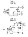
- Fig. lA shows a device of the prior art for measuring the asymmetric frequency spectrum of the scattered millimeter wave based on the new homodyne method.
- a part of the incident wave from a millimeter wave oscillator OSC is applied to a magic-T M i through a directional coupler D., and the incident light is branched to two paths (a) and (b).
- the two paths (a) and (b) are completely symmetrical to each other relative to the magic-T M i except that the path (b) has a 90° phase shifter PS inserted therein.
- Directional couplers D 1 and D 2 are connected to the paths (a) and (b) respectively.
- the coherent millimeter wave from the oscillator OSC is also applied to the transmitter horn PH. through the directional coupler D i , so as to irradiate a plasma PL.
- scattered wave E (t) emanates from the plasma PL and is received by a receiver horn PH.
- the scattered wave E (t) is applied to a magic-T M r and branched toward the two directional couplers D 1 and D 2 .
- the branched scattered waves E s (t) are coupled with the local coherent millimeter waves from the paths (a) and (b) respectively, and then applied to diode mixers X 1 and X 2 . Thereby, homodyne detection is effected, and output intermediate frequency signals V 1 (t) and V 2 (t) are produced.
- the scattered wave E s (t) has an asymmetric frequency spectrum with respect to the frequency ⁇ i of the coherent millimeter wave, as shown in the following equations (1) and (2).
- represents amplitudes of the upper sideband (+) and lower sideband (-) higher harmonic components to be determined by the Fourier series, while ⁇ ⁇ represents phase angles of the upper sideband (+) and lower sideband (-) higher harmonic components.
- the local coherent millimeter waves to be applied to the diode mixers X 1 and X 2 can be given by the following equations.
- is a quantity proportional to the product El ⁇
- the auto- and cross-power-spectral densities ⁇ ik ( ⁇ ) of the intermediate-frequency output signals V 1 (t) and V 2 (t) are determined by the following equation.
- the power spectrum densities of the upper and lower sideband components S ⁇ ( ⁇ ) can be determined from the above auto- and cross-power-spectral densities A G ik ( ⁇ ) by using the following equation.
- Fig. 1B shows the formation of a device of the prior art for measuring asymmetric frequency spectrum in the sub-millimeter wave range, i.e., the quasi-optical frequency range, based on the above new homodyne method for the measurement of the asymmetric frequency spectrum of the scattered wave in the millimeter wave range as explained above by referring to Fig. 1A.
- the formation of Fig. 1B is similar to that of Fig. 1A except that a far infrared radiation laser FIR for the quasi-optical frequency range is used instead of the millimeter wave oscillator OSC of Fig.
- phase shifter PS 1A for the millimeter wave range, that beam splitters BS i are used instead of the directional couplers D i and the magic-T M i and M r of Fig. lA, and that an optical phase shifter PS' consisting of angle mirrors with L-shaped reflective surfaces for elongating the optical path is used instead of the phase shifter PS.
- the above-mentioned new homodyne method for measuring the asymmetric frequency spectrum has shortcomings in that its optical system is complicated due to the need of directional couplers and magic-T's or a comparatively large number of beam splitters BS, and that a high signal-to-noise ratio is hard to obtain because of the considerable loss in the scattered wave signal from the plasma PL at the beam splitters BS, especially at the beam splitters BS1 and BS2 for coupling the scattered light signal from the plasma PL with the local coherent light beam. Accordingly, there is a need for improvement of such new homodyne method.
- diplexers may be used.
- substitution of the beam splitters with the diplexers results in a more complexed optical system due to the increased number of different kinds of optical elements, so that such substitution is not desirable.
- an object of the present invention is to obviate the above-mentioned shortcomings of the prior art by providing an improved system for measuring asymmetric frequency spectrum of an incident wave in optical and/or quasi-optical frequency range, which system is simple in construction and yet ensures highly reliable homodyne detection of the new type with a high signal-to-noise ratio.
- Another object of the invention is to provide a device for measuring asymmetric frequency spectrum, which device is suitable for the measurement of scattered wave in the technical field of nuclear fusion plasma diagnosis, and for the use as demodulators or detectors in the technical field of optical communication.
- a preferred embodiment of the system for measuring asymmetric frequency spectrum by using angle mirrors includes a coherent light beam source for a range covering optical range and/or quasi-optical range, and a first beam splitter is related to the source so as to split a coherent light beam therefrom into a measuring light beam and a local light beam.
- a second beam splitter further splits the local light beam into two auxiliary light beams, and a means is provided for irradiating a specimen with the measuring light beam so as to produce scattered light beam emanating from the specimen.
- a third beam splitter splits the scattered light beam into two main light beams.
- a mirror group is formed by using a pair of angle mirrors disposed symmetrically relative to a line connecting the above second and third beam splitters, each of which angle mirrors is adapted to receive one of the above main light beams and one of the above auxiliary light beams from opposite directions so as to produce reflected parallel light beams from the thus received light beams.
- a pair of condenser lenses are associated with the angle mirrors respectively so as to condense the reflected parallel light beams.
- a means is provided to vary distance between the above angle mirrors along the path of the incident beams thereto in a direction perpendicular to the parallel reflected light beams at one of the angle mirrors.
- a pair of homodyne detectors are associated with the condenser lenses respectively, so as to separately detect asymmetric upper and lower sideband-components in the scattered light beam relative to the carrier frequency ⁇ . thereof.
- the carrier frequency ⁇ i is the frequency of the coherent beam from the source.
- OSC is a millimeter-wave oscillator
- D i , D 1 , D 2 are directional couplers
- PH i and PH r are electromagnetic horns
- PL is a plasma
- PS is a phase shifter
- PS' is an optical phase shifter
- X 1 and X 2 are detectors
- M 1 through M s are mirrors
- BS 1 through BS 5 are beam splitters
- FIR is a far infrared radiation laser
- DT l and DT 2 are optical detectors
- L 1 and L 2 are condenser lenses
- CHM 1 and CHM 2 are angle mirrors with L-shaped reflective surfaces.
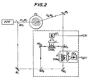
- the system shown in the figure is fot measuring the asymmetric frequency spectrum of scattered waves from a plasma in the range of far infrared radiation based on the principles of the invention.
- a far infrared radiation laser FIR generates a coherent beam with a wave number K i at a frequency ⁇ i .
- a first beam splitter BS 1 splits the coherent beam from the laser FIR into two portions, namely a main beam to be applied to a plasma PL and a local beam.
- the local beam is bent by a mirror M 1 and further split by a second beam splitter BS 2 into two auxiliary beams.
- One of the auxiliary beams is bent by a mirror M 3 and becomes incident to a first angle mirror CHM 1
- the other auxiliary beam is bent by another mirror M 4 and becomes incident to a second angle mirror CHM 2 .
- Each of the angle mirrors CHM 1 and CHM 2 has L-shaped reflective surfaces which cross each other at right angles. When two beams become incident to the angle mirror CHM 1 or CHM 2 from exactly opposite directions, the angle mirror CHM 1 or CHM 2 turns the two opposing incident beams into two parallel reflected beams.
- the plasma PL In response to the application of the main beam from the first beam splitter BS 1 , the plasma PL generates scattered main beam.
- the scattered main beam is bent by a mirror M 2 , and further split by a third beam splitter BS 3 into two split scattered main beams.
- One of the two split scattered main beams becomes incident to the angle mirror CHM 1 in an exactly opposite direction to the above-mentioned incident auxiliary beam thereto, while the other split scattered main beam becomes incident to the other angle mirror CHM 2 in an exactly opposite direction to the above-mentioned incident auxiliary beam thereto, as shown in Fig. 2.
- each of the angle mirrors CHM 1 and CHM 2 turns the incident main beam and the incident auxiliary beam into parallel beams.
- Condenser lenses L 1 and L 2 are associated with the angle mirrors CHM 1 and CHM 2 respectively in such a manner that the parallel reflected beams from each angle mirror are condensed and applied t.o homodyne optical detectors DT 1 and DT 2 respectively.
- the split scattered main beam is treated as a signal beam, while the auxiliary beam is treated as a local beam, so that intermediate-frequency output signals V 1 (t) and V 2 (t) are generated.
- Such intermediate-frequency output signals V 1 (t) and V 2 (t) are, for instance, delivered to a transient recorder (not shown) and recorded therein.
- the two completely identical homodyne detectors DT 1 and DT 2 are disposed substantially symmetrically relative to a plane perpendicular to the plane of the figure and passing the two beam splitters BS 2 and BS 3 .
- the portion enclosed by the dash-dot lines in Fig. 2, i.e., a combination formed of the angle mirror CHM 2 , the condenser lens L 2 , and the homodyne detector DT 2 is mounted on one board, so that the position of the combination can be varied or adjusted as a group, preferably in a fine manner, in a direction of the arrow x perpendicular to the parallel reflected beams.
- the local beam E l (t) and the scattered beam E s (t), both incident to the homodyne detector DT 2 can be given by the following equations without sacrificing any generality.
- K s ( ⁇ i + ⁇ )/c
- K s ' ( ⁇ i - ⁇ )/c
- c is the velocity of light.
- the intermediate-frequency output signal V 1 (t) from the homodyne detector DT 1 can be expressed by an equation that is substantially similar to the equation (9).
- the system for measuring the asymmetric frequency spectrum according to the invention has been described by referring to the embodiment as applied to the measurement of a nuclear fusion plasma.
- the application of the system of the invention is not limited to such measurement, and for instance, it can be applied to the art of optical communication. More particularly, when the system for measuring the asymmetric frequency spectrum according to the invention is applied to the optical communication, the upper sideband and the lower sideband relative to the carrier wave frequency can be used independently for the purpose of communication, and coherent detection of the communication signal wave becomes possible.
- the quantity V 2 thus converted can be given by the following equation.
- the N + ( ⁇ ) component and the N_(w) component can be determined separately from V 1 (t) v of the equation (10a) and V 2 (t) of the equation (11) by using the following equations.
- the system according to the present invention ensures reliable low-noise measurement of asymmetric frequency spectrum of scattered waves having asymmetric frequency spectrum, and the following outstanding effects are achieved by the invention.
- a pair of symmetrically disposed homodyne detectors are used in the system of the invention for measuring asymmetric frequency spectrum.
- the asymmetric frequency spectrum at the upper and lower sidebands can be detected independently and separately only by slightly adjusting the relative distance between the paired homodyne detectors.
- the thus separated signals can be given as the low frequency signals V l (t) of the equation (10a) and the low-frequency signals V 2 (t) of the equation (10b).
- the power spectra S ⁇ ( ⁇ ) of the upper and lower sidebands can be separately determined by using the equations (5) and (6).
- the system of the invention is featured in that such measurement of the asymmetric frequency spectrum can be achieved by a device of simple construction and yet the measurement is highly reliable and the signal-to-noise ratio in the measurement is high.
Landscapes
- Physics & Mathematics (AREA)
- Spectroscopy & Molecular Physics (AREA)
- General Physics & Mathematics (AREA)
- Mathematical Physics (AREA)
- Spectrometry And Color Measurement (AREA)
- Optical Communication System (AREA)
- Investigating Or Analysing Materials By Optical Means (AREA)
Applications Claiming Priority (2)
| Application Number | Priority Date | Filing Date | Title |
|---|---|---|---|
| JP83857/84 | 1984-04-27 | ||
| JP8385784A JPH0789083B2 (ja) | 1984-04-27 | 1984-04-27 | 山形ミラーを用いた新ホモダイン法による非対称スペクトル分布測定装置 |
Publications (3)
| Publication Number | Publication Date |
|---|---|
| EP0160352A2 true EP0160352A2 (de) | 1985-11-06 |
| EP0160352A3 EP0160352A3 (en) | 1986-09-17 |
| EP0160352B1 EP0160352B1 (de) | 1991-02-06 |
Family
ID=13814352
Family Applications (1)
| Application Number | Title | Priority Date | Filing Date |
|---|---|---|---|
| EP19850300283 Expired - Lifetime EP0160352B1 (de) | 1984-04-27 | 1985-01-16 | Doppel-Homodyn-Detektorsystem zum Messen eines asymmetrischen Spektrums unter Verwendung von Winkelspiegeln |
Country Status (4)
| Country | Link |
|---|---|
| US (1) | US4790656A (de) |
| EP (1) | EP0160352B1 (de) |
| JP (1) | JPH0789083B2 (de) |
| DE (1) | DE3581654D1 (de) |
Families Citing this family (2)
| Publication number | Priority date | Publication date | Assignee | Title |
|---|---|---|---|---|
| US5815261A (en) * | 1997-04-16 | 1998-09-29 | General Atomics | Correlation spectrometer with high-resolution, broad-band optical characteristics |
| CN118464874B (zh) * | 2024-07-15 | 2024-10-29 | 中国海洋大学 | 一种水下激光诱导击穿光谱信号增强方法及系统 |
Family Cites Families (3)
| Publication number | Priority date | Publication date | Assignee | Title |
|---|---|---|---|---|
| DE2045386C3 (de) * | 1970-08-07 | 1980-04-03 | Nils Dr.Med. 8035 Gauting Kaiser | Gerät zur Bestimmung des CO2 -Gehaltes einer biologischen Substanz |
| JPS5555266A (en) * | 1978-10-20 | 1980-04-23 | Takashige Chikushima | Spectrum distribution detecting method of receiving wave having asymmetric spectrum distribution |
| FI65332C (fi) * | 1982-06-29 | 1984-04-10 | Labsystems Oy | Foerfarande foer maetning i tvao prov av skillnaden av optiskaegenskaper beroende av ljusets riktning |
-
1984
- 1984-04-27 JP JP8385784A patent/JPH0789083B2/ja not_active Expired - Lifetime
-
1985
- 1985-01-16 EP EP19850300283 patent/EP0160352B1/de not_active Expired - Lifetime
- 1985-01-16 DE DE8585300283T patent/DE3581654D1/de not_active Expired - Lifetime
-
1987
- 1987-04-23 US US07/042,622 patent/US4790656A/en not_active Expired - Fee Related
Also Published As
| Publication number | Publication date |
|---|---|
| DE3581654D1 (de) | 1991-03-14 |
| JPS60228939A (ja) | 1985-11-14 |
| US4790656A (en) | 1988-12-13 |
| JPH0789083B2 (ja) | 1995-09-27 |
| EP0160352A3 (en) | 1986-09-17 |
| EP0160352B1 (de) | 1991-02-06 |
Similar Documents
| Publication | Publication Date | Title |
|---|---|---|
| US5080491A (en) | Laser optical ultarasound detection using two interferometer systems | |
| US5294806A (en) | Optical submicron aerosol particle detector | |
| US8119989B2 (en) | Device and method for terahertz imaging with combining terahertz technology and amplitude-division interference technology | |
| JPS58140338A (ja) | 光フアイバおよび母材の屈折率プロフイルを決定する方法および装置 | |
| Hanson et al. | ATF two‐frequency correlation reflectometer | |
| US5526109A (en) | Multi-velocity component LDV | |
| US7242481B2 (en) | Laser vibrometry with coherent detection | |
| US4263002A (en) | Differential doppler technique for on-axis backscatter measurements | |
| EP0160352B1 (de) | Doppel-Homodyn-Detektorsystem zum Messen eines asymmetrischen Spektrums unter Verwendung von Winkelspiegeln | |
| US5020920A (en) | Method and apparatus for millimeter-wave detection of thermal waves for materials evaluation | |
| US3503682A (en) | Optical mixing devices | |
| Prentice et al. | A two color mm‐wave interferometer for the JET divertora | |
| Beard | Statistics of phase quadrature components of microwave fields transmitted through a random medium | |
| CA1218867A (en) | Method and apparatus for optical tank gauging | |
| JP3096795B2 (ja) | 追尾測距システム | |
| SU1053031A1 (ru) | Измеритель пол ризационных параметров электромагнитной волны | |
| JPS6324147A (ja) | 紙様類の特徴を検出する装置および方法 | |
| Howarth et al. | Analysis of Automatic Homodyne Method Amplitude and Phase Measurements (Short Papers) | |
| JP2507790B2 (ja) | 半導体レ―ザのfm変調特性測定装置 | |
| SU1080084A1 (ru) | Инверсно-дифференциальный лазерный доплеровский измеритель скорости потока жидкости или газа | |
| Brower et al. | The application of homodyne spectroscopy to the study of low-frequency microturbulence in the TEXT tokamak | |
| Pinsonneault et al. | Edge density profile measurements in TdeV using amplitude modulation reflectometry | |
| SU1749838A1 (ru) | Зондирующее устройство | |
| JPH05192302A (ja) | マイクロ波による内部温度分布の計測装置 | |
| Costley et al. | A'comb'reflectometer: A simple device for determining the peak density in difficult experimental situations |
Legal Events
| Date | Code | Title | Description |
|---|---|---|---|
| PUAI | Public reference made under article 153(3) epc to a published international application that has entered the european phase |
Free format text: ORIGINAL CODE: 0009012 |
|
| AK | Designated contracting states |
Designated state(s): DE FR GB |
|
| PUAL | Search report despatched |
Free format text: ORIGINAL CODE: 0009013 |
|
| AK | Designated contracting states |
Kind code of ref document: A3 Designated state(s): DE FR GB |
|
| 17P | Request for examination filed |
Effective date: 19870202 |
|
| 17Q | First examination report despatched |
Effective date: 19890328 |
|
| GRAA | (expected) grant |
Free format text: ORIGINAL CODE: 0009210 |
|
| AK | Designated contracting states |
Kind code of ref document: B1 Designated state(s): DE FR GB |
|
| REF | Corresponds to: |
Ref document number: 3581654 Country of ref document: DE Date of ref document: 19910314 |
|
| ET | Fr: translation filed | ||
| PLBE | No opposition filed within time limit |
Free format text: ORIGINAL CODE: 0009261 |
|
| STAA | Information on the status of an ep patent application or granted ep patent |
Free format text: STATUS: NO OPPOSITION FILED WITHIN TIME LIMIT |
|
| 26N | No opposition filed | ||
| PGFP | Annual fee paid to national office [announced via postgrant information from national office to epo] |
Ref country code: GB Payment date: 19940106 Year of fee payment: 10 |
|
| PGFP | Annual fee paid to national office [announced via postgrant information from national office to epo] |
Ref country code: DE Payment date: 19940110 Year of fee payment: 10 |
|
| PGFP | Annual fee paid to national office [announced via postgrant information from national office to epo] |
Ref country code: FR Payment date: 19940111 Year of fee payment: 10 |
|
| PG25 | Lapsed in a contracting state [announced via postgrant information from national office to epo] |
Ref country code: GB Effective date: 19950116 |
|
| GBPC | Gb: european patent ceased through non-payment of renewal fee |
Effective date: 19950116 |
|
| PG25 | Lapsed in a contracting state [announced via postgrant information from national office to epo] |
Ref country code: FR Effective date: 19950929 |
|
| PG25 | Lapsed in a contracting state [announced via postgrant information from national office to epo] |
Ref country code: DE Effective date: 19951003 |
|
| REG | Reference to a national code |
Ref country code: FR Ref legal event code: ST |