EP0160098A1 - Ink ribbon for sublimation transfer type hard copy - Google Patents
Ink ribbon for sublimation transfer type hard copy Download PDFInfo
- Publication number
- EP0160098A1 EP0160098A1 EP84903765A EP84903765A EP0160098A1 EP 0160098 A1 EP0160098 A1 EP 0160098A1 EP 84903765 A EP84903765 A EP 84903765A EP 84903765 A EP84903765 A EP 84903765A EP 0160098 A1 EP0160098 A1 EP 0160098A1
- Authority
- EP
- European Patent Office
- Prior art keywords
- ink ribbon
- heat
- layer
- hard copy
- base
- Prior art date
- Legal status (The legal status is an assumption and is not a legal conclusion. Google has not performed a legal analysis and makes no representation as to the accuracy of the status listed.)
- Granted
Links
Images


Classifications
-
- B—PERFORMING OPERATIONS; TRANSPORTING
- B41—PRINTING; LINING MACHINES; TYPEWRITERS; STAMPS
- B41M—PRINTING, DUPLICATING, MARKING, OR COPYING PROCESSES; COLOUR PRINTING
- B41M5/00—Duplicating or marking methods; Sheet materials for use therein
- B41M5/26—Thermography ; Marking by high energetic means, e.g. laser otherwise than by burning, and characterised by the material used
- B41M5/40—Thermography ; Marking by high energetic means, e.g. laser otherwise than by burning, and characterised by the material used characterised by the base backcoat, intermediate, or covering layers, e.g. for thermal transfer dye-donor or dye-receiver sheets; Heat, radiation filtering or absorbing means or layers; combined with other image registration layers or compositions; Special originals for reproduction by thermography
- B41M5/42—Intermediate, backcoat, or covering layers
- B41M5/44—Intermediate, backcoat, or covering layers characterised by the macromolecular compounds
Definitions
- the present invention relates to an ink ribbon for a sublimation transfer type hard copy used to produce a hard copy of a still picture image such as a picture image taken by a video camera, a television picture image and so on.
- Fig. 1 shows an example of a prior art printer for a sublimation transfer type hard copy.
- This printer comprises a platen 2 having wound therearound a printing paper 1 and which is rotatable in the direction shown by an arrow a and a thermal print head 4 which is urged against the platen across an ink ribbon 3 for use in thermal transfer recording.
- heat generating elements 4a On the point of the thermal print head 4, there are arranged heat generating elements 4a whose total number corresponds to the number of picture elements in one scanning line of, for example, a television picture image.
- the ink ribbon 3 for use in thermal transfer recording tightly pressed between the thermal print head 4 and the printing paper 1 is formed of a film base 9 on which, for example, an yellow ink layer Y, a magenta ink layer M, a cyan ink layer C and a black ink layer B each having a configuration corresponding to a configuration of a picture screen of a television picture image are repeatedly arranged in turn.
- ink portion position detecting marks 5Y, 5M, 5C and 5B are respectively formed on one side edge of the film base at the positions of the corresponding color ink portions so as to detect the positions of the ink portions and a block position detecting mark 6 is formed on the other side edge of the film base so as to detect each combination group of four colors of Y, M, C and B.
- each head element 4a of the thermal print head 4 is heated with a pattern corresponding to the picture elements of one scanning line to thereby thermally transfer the yellow sublimation dye contained in the yellow ink layer Y to the printing paper 1 in accordance with the heated pattern.
- the platen 2 is intermittently rotated in the direction shown by the arrow a to thereby carry out the thermal transfer of information of each line.
- the platen 2 is rotated one turn, the yellow color of one picture screen amount is transferred.
- a similar transfer treatment is carried out with respect to the magenta color and subsequently, the cyan color and the black color are sequentially transferred repeatedly to thereby superpose the transferred picture images of the sublimation dyes of the yellow, magenta, cyan and black sublimation dyes one another, thus a color picture image being printed on the printing paper.
- detecting means are provided to detect the marks 5 (5Y, 5M, 5C and 5B) and 6 in the ink layers Y, M, C and B of respective colors for the purpose of supplying the signals corresponding to the respective color signals to the head elements 4a of the thermal print head 4.
- This detecting means includes, for example, a light source 7 for emitting a light ray for use in detection, for example, an infrared ray emitting diode and a detecting element 8 for detecting the infrared ray in which case, both of them are disposed in opposing relation to each other at both sides of the ink ribbon 3 for use in thermal transfer recording at which the marks 5 and 6 are provided.
- the detecting element 8 produces a detected signal dependent on the presence or absence of the marks 5 and 6 whereby to detect the positional relation of the ink ribbon 3 for use in thermal transfer recording relative to the thermal print head 4.
- the ink ribbon for such sublimation transfer type hard copy there is used in the art such one that is formed such that on a film base 9 made of a paper such as a condenser paper, which is thin, uniform and dense, there is formed a coating layer made of an ink in which a sublimation dye is dissolved and dispersed into resin and solvent.
- a film base 9 made of a paper such as a condenser paper, which is thin, uniform and dense
- a coating layer made of an ink in which a sublimation dye is dissolved and dispersed into resin and solvent.
- the amount of water component contained in the paper is very small, the water is boiled up momentarily by the thermal print head 4 heated around 400°C; producing a bubble spot ' 'in the film base 9.
- the fact that the heat is absorbed by the water upon boiling decreases sublimation amount of dye in the ink robbon 3 and causes the bubble spot in the picture image as a density spot, thus lowering the picture quality considerably.
- a protecting layer On the other hand, on the surface of the printing paper 1 which is the transferred paper, after the sublimation dye is transferred thereto, there is provided a protecting layer.
- This protecting layer is to avoid such defects that when the protecting layer is not provided, the dye which is not diffused into the coating composition layer formed on the printing paper 1 but adhering to its surface is rubbed to be dropped in color and that if this dye is left as it is, the dye is transferred to pollute other materials. Further, since the dye coagulated on the coating composition layer can not produce the color inherent to the dye if the dye is left as it is, it is necessary that the coagulated dye is diffused sufficiently into the protecting layer to complete the coloring inherent to the dye.
- the present applicant has previously proposed a method for forming a cover film by a laminator, a method for forming a protecting layer in which without using the laminator, the cover film layer formed on the ink ribbon is pressed by the same thermal print head so as to produce the protecting layer and so on.
- the protecting layer can be formed on the printing paper 1 very easily.
- the film base of the ink ribbon on which the cover film layer is formed is made of condenser paper similarly to the prior art, there are the following problems.
- the releasing treatment when a resin layer which becomes the cover film layer is formed on the surface of the condenser paper, the releasing treatment must be carried out so as to prevent the resin layer and the condenser paper from being melt bonded.
- the dye coating"layer must be bonded well to the condenser paper so that it is difficult to carry out the releasing treatment available only to the necessary portion and to carry out the complete releasing treatment in a manufacturing standpoint. Further, even if the releasing treatment is carried out, to the surface of the protecting layer the form of concavity and convexity peculiar to the condenser paper is transferred and hence the protecting layer having the smooth surface is not formed, thus the protecting layer being made insufficient in external appearance.
- this invention is to provide an ink ribbon for sublimation transfer type hard copy which is free of a shrinking of a film base, a bubble spot formed in the film base and so on caused by heat generated upon transfer so that an excellent picture quality can be obtained.
- This invention relates to an ink ribbon for sublimation transfer type hard copy, in which an ink layer of sublimation dye is formed on a heat-resistant plastic film base or a plastic film base having formed thereon a heat-resistant coating composition layer.
- this invention relates to an ink ribbon for sublimation transfer type hard copy in which under the condition that the ink ribbon carrying a sublimation dye and a printing paper are in contact with each other, a picture image is formed on the printing paper by a selective heating treatment, wherein the ink ribbon is formed by forming a coating layer of sublimation dye on a heat-resistant plastic film base or a plastic film base having formed thereon a heat-resistant coating composition layer.
- a heat-resistant plastic film 12 having no melting point on which a sublimation dye coating layer 13 is formed to thereby make an ink ribbon 11.
- the ink ribbon is an ink ribbon for use with a color picture image
- the base 12 there are repeatedly formed the coating layers 13 of yellow, magenta, cyan and black colors in turn, whereas if the ink ribbon is an ink ribbon for use with a black and white picture image, only the coating layer 13 of black color is formed on the base 12.
- plastic such as polymide, polyamide, aromatic polybenzimidasol and so on which begin to be carbonized or decomposed before being melted by heat and a moisture proof cellophane.
- a plastic film base 16 in which a normal plastic film 14 is formed thereon with a heat-resistant treating layer 15 which does not have melting point and on the surface of the plastic film on which the heat-resistant treating layer 15 is not formed, there is formed a sublimation dye coating layer 13 to thereby form an ink ribbon 11.
- the ordinary plastic may be polyester, such as, polyethylene telephthalate, polyacrylate, polyethersulfon and so on which can not endure the heat generated from the thermal print head but has a relatively high heat-resistant property and which is also inexpensive.
- the heat-resistant treating layer 15 made of a substance which does not have melting point is formed such that a resin such as nitrocellulose and polyimide lacquer which begin to be carbonized or decomposed before being melted by heat or a heat curable heat-resistant resin such as melamine resin, aminoalkyd resin, epoxy resin, silicone denatured epoxy resin and so on or unsaturared polyester and unsaturated oligomer such as epoxy acrylate is mixed with a curing agent, coated and then cured.
- the heat-resistant treating layer may be made of coating layer containing a denatured silicone resin denatured by a resin such as alkyd resin, epoxy resin, acrylic resin or urethane resin and so on.
- the denatured silicone resin is mixed with melamine resin or imidasol and the like, coated and then cured to thereby form the heat-resistant treating layer.
- the thickness of the treating layer 15 is not limited particularly but preferably selected in a range from 1 ⁇ m to 10pm.
- a coating material in which a heat-resistant powder is dispersed into the resin available for forming the heat-resistant treating layer may be used to form the heat-resistant treating layer 15 of this ink ribbon 11.
- the heat-resistant powder may be inorganic powder such as silica, calcium carbonate, titanium oxide, carbon, graphite and so on, heat-resistant organic powder such as teflon, silicone, cellulose powder and so on.
- the heat-resistant treating layer 15 contains the heat-resistant powder, the friction coefficient between the ink ribbon 11 and the thermal print head can be lowered to thereby enable the ink ribbon to smoothly slide on the thermal print head.
- Fig. 5 shows a further embodiment of this invention in which a lubricant layer 35 is formed on the heat-resistant treating layer 15 of the ink ribbon having the heat-resistant treating layer 15 shown in Fig. 3.
- This lubricant layer ensures that the ink ribbon can slide on the thermal print head smoothly.
- This lubricant layer can be formed by coating on the layer a releasing agent such as silicone resin and the like.
- a plastic film base 16 in which the heat-resistant treating layers 15 are formed on the both surfaces of the ordinary plastic film 14 is used and the sublimation dye coating layer 13 is formed on the surface of one of the heat-resistant treating layers, thus the ink ribbon 11 being formed.
- plastic material such as polyimide having a high heat-resistant property
- plastic film can be used, as it is, as the plastic film base 16 of this invention.
- the ink ribbon is formed as described above, the price thereof is increased generally.
- the heat-resistant treating layer 15 is formed on the surface of the inexpensive plastic film of thermoplastic property such as a polyester film base which can not endure the heat generated from the thermal print head by itself and which is difficult to be used as the film base of the ink ribbon, it is possible to make the ink ribbon 11 of this invention having a sufficiently high heat-resistant property.
- the heat-resistant treating layer 15 is formed on the surface of the plastic film, if the ink ribbon is exposed in a high temperature of about 400°C for a long time, the treating layer 15 and the plastic film 14 are both melted.
- the heating by the thermal print head lasts for a very short time of period ranging from several tens microseconds to several tens milliseconds so that the plastic film 14 is not melted and thus the heat-resistant property of the treating layer 15 can prevent the ink ribbon 11 from being melt bonded and deformed.
- the heat-resistant plastic film base or the plastic film base having formed thereon the heat-resistant treating layer is used so that such film base contains no water component, thus the picture image becomes free of the bubble spot completely. Further, contrary to the condenser paper, the plastic film is swollen a little by the heating so that the ink ribbon in contact with the printing paper is not wrinkled. Accordingly, it is possible to increase'the quality of the transferred picture image considerably.
- Fig. 6 illustrates other embodiment of the present invention which utilizes the fundamental structure of the above-described present invention.
- the present invention is applied to an ink ribbon for a color picture image in which after the picture image is formed, the protecting layer can be formed successively.
- the coating layers 13 mainly made of the sublimation dye are formed sequentially as in the order of yellow Y, magenta M, cyan C and black B (this can be provided as required).
- This cover film layer 10 is made of a transparent resin layer which can not be bonded to the plastic film base 12 or 16 but can easily be melt bonded to the surface of the printing paper.
- the thickness of the cover film layer 10 is in a range from 1 to 10u.
- the material of this cover film layer may be polyester resin, epoxy resin, cellulose acetate resin, nylon resin, polyvinylpyrrolidone resin and so on, each having a melt bonding property.
- the releasing treatment can be carried out between the base film 12 or 16 and the'cover film layer 10.
- the cover film layer 10 may contain an ultraviolet absorbent or phosphor whitener and so on, if necessary.
- Reference numeral 22 designates a sensor mark for use in determining the position.
- Fig. 7 illustrates a state of a transfer treatment which uses such ink ribbon 31.
- Reference numeral 17 designates a printing paper in which a dye diffusing layer 19 is formed on the surface of a base 18.
- Reference numeral 23 designates a platen which moves the printing paper 17 and
- reference numeral 21 designates a thermal print head which is provided at its point with heat generating elements whose number is corresponding to the number of the picture elements in one scanning line of the picture image.
- the ink ribbon 31 is tightly pressed against the printing paper 17 by the thermal print head 21. In this ink ribbon 31, in like manner described in connection with Fig.
- each heat generating element of the thermal print head 21 is supplied with the electric power in accordance with the video signal so as to sequentially sublimate and transfer the dyes of yellow Y, magenta M, cyan C and black B in response to the heated amount, thus forming a color picture image on the printing paper 17.
- the ink ribbon 31 is heated at its portion of the cover film layer 10 by the thermal print head 21 to thereby melt bond the cover film layer 10 to the printing paper 17.
- a dye coagulated material 24 of picture image transferred from the ink ribbon 31 is diffused into the cover film layer 10 and the dye diffusing layer 19 of the printing paper 17.
- Reference numeral 25 designates the dye that is diffused as mentioned above.
- the cover film layer is formed.
- the heat-resistant plastic film base 12 (or 16) so that the bubble spot caused by the evaporation of water component and the wrinkles will not appear and in addition, the protecting layer having the smooth surface can be formed.
- the releasing treatment may be carried out over the portion of the protecting layer and further, a primer treatment may be carried out over the portion in which each color coating layer is formed.
- a treating liquid made of 24 parts by weight of internally plasticized saturated polyester resin (VYLON #200 manufactured by Toyobo Co., Ltd.), 6 parts by weight of super fine powder silica (NIPSIL E220A manufactured by Nippon Silica Industrial Co., Ltd.) and 70 parts by weight of methyl ethyl ketone solvent was coated on one surface of a best quality paper having an area weight of 170g/m 2 so as to have a coated amount of about 5g/m 2 after being dried, thus a printing paper for sublimation transfer type color hard copy being prepared.
- the ink of magenta color such as an ink made of 6 parts by weight of dispersion dye (PTR 63 manufactured by Mitsubishi Chemical Industries Co., Ltd.) of anthraquinone-system having a sublimation property
- 6 parts by weight of ethylcellulose and 88 parts by weight of isopropyl alcohol solvent like inks of cyan color, yellow color and black color were respectively provided.
- the inks of 4 colors were successively coated by a gravure coater so as to have a coated amount of 3g/m 2 after being dried.
- an ultraviolet absorbent Tinuvin P manufactured by Ciba Geigy A.G.
- VYLON #200 manufactured by Toyobo Co., Ltd. was internally plasticized with a mixing ratio of 0.2 weight % relative to the resin so as to have a thickness of 10pm after being dried to thereby form a cover film.
- this ink ribbon was heated from the back thereof by the thermal print head heated at a temperature of about 300°C to sequentially print the four colors on the above-described printing paper to thereby provide a color print and then the cover film layer was formed on the picture image. It was discovered that the picture image thus formed have no bubble spot due to the evaporation of water component and no displacement of the picture image.
- An ink ribbon 32 for a black and white picture image is formed such that as shown in Fig. 8, the coating layer B of black color ink and the cover film layer 10 are sequentially formed.
- a base material 14 was made by a polyester film having a thickness of 8pm. On one surface of this base material 14, there was coated a resin liquid having the following composition by a pipe coater such that the heat-resistant treating layer 15 might have a thickness of 3pm after being dried. Thereafter, at a temperature of 130°C, it was heated and then cured for an hour.
- the heat-resistant treating layer 15 was made by the resin liquid having the above-described composition, on the surface opposing to the surface in contact with the thermal print head 4, there was coated a resin liquid having the following composition to thereby form the ink layer 13 of thermal transfer property, thus an ink ribbon for sublimation transfer recording of this example being formed.
- the above resin liquid was printed through a printing plate having a depth of 45 ⁇ m and 185 lines/inch.
- the ink ribbon 11 for sublimation transfer recording which was formed in the above-described Example 2 was manufactured. Then, on the upper surface of the heat-resistant treating layer 15, there was coated a resin liquid having the following composition available for the purpose of lowering the friction coefficient upon transportation by using a gravure coater through a printing plate having a depth of 20pm and 200 lines/inch. This product was placed at a temperature of 130°C for 5 minutes and then cured to form the lubricant layer 35 (see Fig. 5), thus an ink ribbon for sublimation transfer recording of this example being produced.
- the base material 14 was formed by the polyester film having the thickness of 8 ⁇ m. Then, on one surface of this plastic base material 14, there was coated a resin liquid having the following composition by a pipe coater such that the heat-resistant treating layer 15 may have the thickness of Sum after being dried. Thereafter, it was heated at a temperature of 130°C for an hour and then cured.
- thermo transfer ink layer 13 After the heat-resistant treating layer 15 was formed by the resin liquid having the above-described composition, on the surface opposing to the surface in contact with the thermal print head 4, there was coated a resin liquid having the following composition, thus a thermal transfer ink layer 13 being made.
- the resin liquid was printed through a printing plate having a depth of 45pm and 185 lines/inch and thus the ink ribbon for sublimation transfer recording was formed.
- the base material 14 was formed by the polyester film having the thickness of 6pm. On one surface of the base material 14, there was coated a resin liquid having the following composition by a pipe coater so that the heat-resistant treating layer 15 might have the thickness of 6pm after being dried. Thereafter, it was heated at a temperature of 130°C for an hour and then cured.
- the heat-resistant treating layer 15 was formed by the resin liquid having the above-described composition, on the surface opposing to the surface in contact with the thermal print head, there was coated a resin liquid of the following composition, thus the ink layer 13 having the thermal transfer property being formed.
- this coating composition was coated through a printing plate having a depth of 45 ⁇ m and 185 lines/inch and thus the ink ribbon for sublimation transfer recording of this example was formed.
- Fig. 9 illustrates a further embodiment of this invention.
- the coloring inherent to the dye can be developed and a coagulated material 24 of dye deposited on the printing paper 17 can be diffused well into the dye diffusing layer 19;
- the heat amount of the thermal print head 21 for such re-heating of the picture image is free from the restriction put by the signal that forms the picture image and becomes an electric power required by the whole of the resistor elements of the thermal print head 21 to diffuse the dye well.
- Such re-heating can be carried out a plurality of times by using the same portion 26 in which no coating layer is formed and this ensures that the dye can be fixed more completely. Further, as shown in Fig.
- the thin film 27 which is hard to be diffused with the dye can be obtained by coating casein, coating and curing a curable heat-resistant resin such as polyimide resin, silicone resin, melamine resin and so on, metal plating, metal thin film treatment and so on.
- the picture image can be fixed without using the protecting layer. Since the protecting layer is not used, the printing paper can be protected from the deformation such as curl and so on.
- Fig. 11 illustrates an embodiment in which the above-described structure is applied to an ink ribbon 34 for a black and white picture image.
- the black color coating layer B next to the black color coating layer B, there is formed the portion 26 having no coating layer.
- the heat-resistant plastic film base or the plastic film base having formed thereon the heat-resistant treating layer contains no water component and produces no bubble unlike the prior art so that the bubble spot is removed from the picture image completely.
- the film base can be prevented from being shrunk largely by the heating and the film base is rather swollen a little so that no wrinkle is produced between the film base and the printing paper.
- the quality of the transferred picture image can be improved.
Abstract
Description
- The present invention relates to an ink ribbon for a sublimation transfer type hard copy used to produce a hard copy of a still picture image such as a picture image taken by a video camera, a television picture image and so on.
- Fig. 1 shows an example of a prior art printer for a sublimation transfer type hard copy. This printer comprises a platen 2 having wound therearound a
printing paper 1 and which is rotatable in the direction shown by an arrow a and athermal print head 4 which is urged against the platen across an ink ribbon 3 for use in thermal transfer recording. - On the point of the
thermal print head 4, there are arranged heat generating elements 4a whose total number corresponds to the number of picture elements in one scanning line of, for example, a television picture image. - The ink ribbon 3 for use in thermal transfer recording tightly pressed between the
thermal print head 4 and theprinting paper 1 is formed of a film base 9 on which, for example, an yellow ink layer Y, a magenta ink layer M, a cyan ink layer C and a black ink layer B each having a configuration corresponding to a configuration of a picture screen of a television picture image are repeatedly arranged in turn. Further, ink portionposition detecting marks - Under the condition that the yellow ink layer Y, for example, is urged against the
printing paper 1 as described above, by an information corresponding to yellow, for example, a color signal corresponding to yellow of a television video signal, each head element 4a of thethermal print head 4 is heated with a pattern corresponding to the picture elements of one scanning line to thereby thermally transfer the yellow sublimation dye contained in the yellow ink layer Y to theprinting paper 1 in accordance with the heated pattern. - At every line corresponding to each scanning line, the platen 2 is intermittently rotated in the direction shown by the arrow a to thereby carry out the thermal transfer of information of each line. When the platen 2 is rotated one turn, the yellow color of one picture screen amount is transferred. Then, a similar transfer treatment is carried out with respect to the magenta color and subsequently, the cyan color and the black color are sequentially transferred repeatedly to thereby superpose the transferred picture images of the sublimation dyes of the yellow, magenta, cyan and black sublimation dyes one another, thus a color picture image being printed on the printing paper. In this case, detecting means are provided to detect the marks 5 (5Y, 5M, 5C and 5B) and 6 in the ink layers Y, M, C and B of respective colors for the purpose of supplying the signals corresponding to the respective color signals to the head elements 4a of the
thermal print head 4. This detecting means includes, for example, alight source 7 for emitting a light ray for use in detection, for example, an infrared ray emitting diode and a detectingelement 8 for detecting the infrared ray in which case, both of them are disposed in opposing relation to each other at both sides of the ink ribbon 3 for use in thermal transfer recording at which themarks 5 and 6 are provided. - In the detecting means, the detecting
element 8 produces a detected signal dependent on the presence or absence of themarks 5 and 6 whereby to detect the positional relation of the ink ribbon 3 for use in thermal transfer recording relative to thethermal print head 4. - As the ink ribbon for such sublimation transfer type hard copy, there is used in the art such one that is formed such that on a film base 9 made of a paper such as a condenser paper, which is thin, uniform and dense, there is formed a coating layer made of an ink in which a sublimation dye is dissolved and dispersed into resin and solvent. As described above, since in the prior art ink ribbon, the paper is used as the film base 9, when the ink robbon 3 is heated by the
thermal print head 4, the water component contained in the paper is evaporated and the film base 9 is considerably shrunk to thereby produce wrinkles between the printing paper and the ink robbon 3, thus lowering the picture quality. Although the amount of water component contained in the paper is very small, the water is boiled up momentarily by thethermal print head 4 heated around 400°C; producing a bubble spot''in the film base 9. The fact that the heat is absorbed by the water upon boiling decreases sublimation amount of dye in the ink robbon 3 and causes the bubble spot in the picture image as a density spot, thus lowering the picture quality considerably. - On the other hand, on the surface of the
printing paper 1 which is the transferred paper, after the sublimation dye is transferred thereto, there is provided a protecting layer. This protecting layer is to avoid such defects that when the protecting layer is not provided, the dye which is not diffused into the coating composition layer formed on theprinting paper 1 but adhering to its surface is rubbed to be dropped in color and that if this dye is left as it is, the dye is transferred to pollute other materials. Further, since the dye coagulated on the coating composition layer can not produce the color inherent to the dye if the dye is left as it is, it is necessary that the coagulated dye is diffused sufficiently into the protecting layer to complete the coloring inherent to the dye. As a method for forming such protecting layer available to the above-described objects, the present applicant has previously proposed a method for forming a cover film by a laminator, a method for forming a protecting layer in which without using the laminator, the cover film layer formed on the ink ribbon is pressed by the same thermal print head so as to produce the protecting layer and so on. By virtue of such technique, the protecting layer can be formed on theprinting paper 1 very easily. However, since the film base of the ink ribbon on which the cover film layer is formed is made of condenser paper similarly to the prior art, there are the following problems. That is, when a resin layer which becomes the cover film layer is formed on the surface of the condenser paper, the releasing treatment must be carried out so as to prevent the resin layer and the condenser paper from being melt bonded. However, the dye coating"layer must be bonded well to the condenser paper so that it is difficult to carry out the releasing treatment available only to the necessary portion and to carry out the complete releasing treatment in a manufacturing standpoint. Further, even if the releasing treatment is carried out, to the surface of the protecting layer the form of concavity and convexity peculiar to the condenser paper is transferred and hence the protecting layer having the smooth surface is not formed, thus the protecting layer being made insufficient in external appearance. - In view of the above-described aspect, this invention is to provide an ink ribbon for sublimation transfer type hard copy which is free of a shrinking of a film base, a bubble spot formed in the film base and so on caused by heat generated upon transfer so that an excellent picture quality can be obtained.
- This invention relates to an ink ribbon for sublimation transfer type hard copy, in which an ink layer of sublimation dye is formed on a heat-resistant plastic film base or a plastic film base having formed thereon a heat-resistant coating composition layer.
- Further, this invention relates to an ink ribbon for sublimation transfer type hard copy in which under the condition that the ink ribbon carrying a sublimation dye and a printing paper are in contact with each other, a picture image is formed on the printing paper by a selective heating treatment, wherein the ink ribbon is formed by forming a coating layer of sublimation dye on a heat-resistant plastic film base or a plastic film base having formed thereon a heat-resistant coating composition layer.
- According to such ink ribbon, it is possible to protect the film base from being shrunk and producing a bubble spot therein due to heat generated upon transfer, etc. Accordingly, a quality of a transferred picture image can be improved.
-
- Fig. 1 is a perspective view of a prior art printer for sublimation transfer type hard copy;
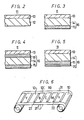
- Figs. 2 to 5 are respectively cross-sectional views showing embodiments of an ink ribbon according to the present invention;
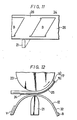
- Fig. 6 is a perspective view of an ink ribbon for a color picture image;
- Fig. 7 is a side view showing the ink ribbon of the present invention which is in its use mode;
- Fig. 8 is a perspective view of an ink ribbon for a black and white picture image;
- Figs. 9 to 11 are respectively perspective views showing other embodiments of the ink ribbon according to the present invention; and
- Fig. 12 is a side view showing the ink ribbon of the above embodiments which is in its use mode.
- In a first embodiment of the present invention, as shown in Fig. 2, as the film base, there is used a heat-resistant
plastic film 12 having no melting point on which a sublimationdye coating layer 13 is formed to thereby make anink ribbon 11. In this case, if the ink ribbon is an ink ribbon for use with a color picture image, on thebase 12, there are repeatedly formed thecoating layers 13 of yellow, magenta, cyan and black colors in turn, whereas if the ink ribbon is an ink ribbon for use with a black and white picture image, only thecoating layer 13 of black color is formed on thebase 12. - As the heat-resistant plastic which does not have melting point, it is possible to use plastic such as polymide, polyamide, aromatic polybenzimidasol and so on which begin to be carbonized or decomposed before being melted by heat and a moisture proof cellophane.
- In a second embodiment of the present invention, as shown in Fig. 3, as the film base, there is used a
plastic film base 16 in which a normalplastic film 14 is formed thereon with a heat-resistant treatinglayer 15 which does not have melting point and on the surface of the plastic film on which the heat-resistant treatinglayer 15 is not formed, there is formed a sublimationdye coating layer 13 to thereby form anink ribbon 11. - The ordinary plastic may be polyester, such as, polyethylene telephthalate, polyacrylate, polyethersulfon and so on which can not endure the heat generated from the thermal print head but has a relatively high heat-resistant property and which is also inexpensive. The heat-resistant treating
layer 15 made of a substance which does not have melting point is formed such that a resin such as nitrocellulose and polyimide lacquer which begin to be carbonized or decomposed before being melted by heat or a heat curable heat-resistant resin such as melamine resin, aminoalkyd resin, epoxy resin, silicone denatured epoxy resin and so on or unsaturared polyester and unsaturated oligomer such as epoxy acrylate is mixed with a curing agent, coated and then cured. Alternatively, the heat-resistant treating layer may be made of coating layer containing a denatured silicone resin denatured by a resin such as alkyd resin, epoxy resin, acrylic resin or urethane resin and so on. - Then, the denatured silicone resin is mixed with melamine resin or imidasol and the like, coated and then cured to thereby form the heat-resistant treating layer. The thickness of the treating
layer 15 is not limited particularly but preferably selected in a range from 1µm to 10pm. - A coating material in which a heat-resistant powder is dispersed into the resin available for forming the heat-resistant treating layer may be used to form the heat-resistant treating
layer 15 of thisink ribbon 11. - The heat-resistant powder may be inorganic powder such as silica, calcium carbonate, titanium oxide, carbon, graphite and so on, heat-resistant organic powder such as teflon, silicone, cellulose powder and so on.
- As described above, since the heat-resistant treating
layer 15 contains the heat-resistant powder, the friction coefficient between theink ribbon 11 and the thermal print head can be lowered to thereby enable the ink ribbon to smoothly slide on the thermal print head. - Fig. 5 shows a further embodiment of this invention in which a
lubricant layer 35 is formed on the heat-resistant treatinglayer 15 of the ink ribbon having the heat-resistant treatinglayer 15 shown in Fig. 3. This lubricant layer ensures that the ink ribbon can slide on the thermal print head smoothly. This lubricant layer can be formed by coating on the layer a releasing agent such as silicone resin and the like. - In a third embodiment of the present invention, as shown in Fig. 4, a
plastic film base 16 in which the heat-resistant treatinglayers 15 are formed on the both surfaces of the ordinaryplastic film 14 is used and the sublimationdye coating layer 13 is formed on the surface of one of the heat-resistant treating layers, thus theink ribbon 11 being formed. - When the plastic material such as polyimide having a high heat-resistant property is selected to be the material of the film base as in the first embodiment, such plastic film can be used, as it is, as the
plastic film base 16 of this invention. However, if the ink ribbon is formed as described above, the price thereof is increased generally. - For this reason, as shown in the second and third embodiments, if the heat-resistant treating
layer 15 is formed on the surface of the inexpensive plastic film of thermoplastic property such as a polyester film base which can not endure the heat generated from the thermal print head by itself and which is difficult to be used as the film base of the ink ribbon, it is possible to make theink ribbon 11 of this invention having a sufficiently high heat-resistant property. Although the heat-resistant treatinglayer 15 is formed on the surface of the plastic film, if the ink ribbon is exposed in a high temperature of about 400°C for a long time, the treatinglayer 15 and theplastic film 14 are both melted. However, the heating by the thermal print head lasts for a very short time of period ranging from several tens microseconds to several tens milliseconds so that theplastic film 14 is not melted and thus the heat-resistant property of the treatinglayer 15 can prevent theink ribbon 11 from being melt bonded and deformed. - As described above, as the film base of the ink ribbon for sublimation transfer type hard copy, the heat-resistant plastic film base or the plastic film base having formed thereon the heat-resistant treating layer is used so that such film base contains no water component, thus the picture image becomes free of the bubble spot completely. Further, contrary to the condenser paper, the plastic film is swollen a little by the heating so that the ink ribbon in contact with the printing paper is not wrinkled. Accordingly, it is possible to increase'the quality of the transferred picture image considerably.
- Fig. 6 illustrates other embodiment of the present invention which utilizes the fundamental structure of the above-described present invention. Particularly in this case, the present invention is applied to an ink ribbon for a color picture image in which after the picture image is formed, the protecting layer can be formed successively.
- In this embodiment, on one surface of the heat-resistant plastic film or the plastic film base 12 (or 16) on which the heat-resistant treating layer is formed, the coating layers 13 mainly made of the sublimation dye are formed sequentially as in the order of yellow Y, magenta M, cyan C and black B (this can be provided as required).
- Between the adjacent combinations of the ink layers 13 (Y, M, C and B) of 4 colors, there is formed a protecting layer or a
cover film layer 10 to thereby form anink ribbon 31 for a color picture image. Thiscover film layer 10 is made of a transparent resin layer which can not be bonded to theplastic film base cover film layer 10 is in a range from 1 to 10u. The material of this cover film layer may be polyester resin, epoxy resin, cellulose acetate resin, nylon resin, polyvinylpyrrolidone resin and so on, each having a melt bonding property. As required, the releasing treatment can be carried out between thebase film the'cover film layer 10. Thecover film layer 10 may contain an ultraviolet absorbent or phosphor whitener and so on, if necessary.Reference numeral 22 designates a sensor mark for use in determining the position. - Fig. 7 illustrates a state of a transfer treatment which uses
such ink ribbon 31.Reference numeral 17 designates a printing paper in which adye diffusing layer 19 is formed on the surface of abase 18.Reference numeral 23 designates a platen which moves theprinting paper 17 andreference numeral 21 designates a thermal print head which is provided at its point with heat generating elements whose number is corresponding to the number of the picture elements in one scanning line of the picture image. Theink ribbon 31 is tightly pressed against theprinting paper 17 by thethermal print head 21. In thisink ribbon 31, in like manner described in connection with Fig. 1, each heat generating element of thethermal print head 21 is supplied with the electric power in accordance with the video signal so as to sequentially sublimate and transfer the dyes of yellow Y, magenta M, cyan C and black B in response to the heated amount, thus forming a color picture image on theprinting paper 17. Thereafter, theink ribbon 31 is heated at its portion of thecover film layer 10 by thethermal print head 21 to thereby melt bond thecover film layer 10 to theprinting paper 17. When thecover film layer 10 is melt bonded to the printing paper, a dye coagulatedmaterial 24 of picture image transferred from theink ribbon 31 is diffused into thecover film layer 10 and thedye diffusing layer 19 of theprinting paper 17.Reference numeral 25 designates the dye that is diffused as mentioned above. - As set forth above, at the same time when the color picture image is formed, the cover film layer is formed. According to
such ink ribbon 31 for a color picture image, as the film base thereof, there is used the heat-resistant plastic film base 12 (or 16) so that the bubble spot caused by the evaporation of water component and the wrinkles will not appear and in addition, the protecting layer having the smooth surface can be formed. In the plastic film base 12 (or 16), if necessary, the releasing treatment may be carried out over the portion of the protecting layer and further, a primer treatment may be carried out over the portion in which each color coating layer is formed. - Practical examples of the
ink ribbon 31 for a color picture image will be described next. - A treating liquid made of 24 parts by weight of internally plasticized saturated polyester resin (VYLON #200 manufactured by Toyobo Co., Ltd.), 6 parts by weight of super fine powder silica (NIPSIL E220A manufactured by Nippon Silica Industrial Co., Ltd.) and 70 parts by weight of methyl ethyl ketone solvent was coated on one surface of a best quality paper having an area weight of 170g/m2 so as to have a coated amount of about 5g/m2 after being dried, thus a printing paper for sublimation transfer type color hard copy being prepared. On the other hand, in addition to the ink of magenta color such as an ink made of 6 parts by weight of dispersion dye (PTR 63 manufactured by Mitsubishi Chemical Industries Co., Ltd.) of anthraquinone-system having a sublimation property, 6 parts by weight of ethylcellulose and 88 parts by weight of isopropyl alcohol solvent, like inks of cyan color, yellow color and black color were respectively provided. Then, on a polyimide film having a thickness ranging from 5 to 50µm or 25µm in this example, the inks of 4 colors were successively coated by a gravure coater so as to have a coated amount of 3g/m2 after being dried. Further, on the surface of the polyimide base having the thickness of 25um whose one surface is subjected to the releasing treatment between the adjacent groups of the ink portions of 4 colors, there was coated a resin liquid in which an ultraviolet absorbent (Tinuvin P manufactured by Ciba Geigy A.G.) was dissolved and mixed into a saturated polyester resin (VYLON #200 manufactured by Toyobo Co., Ltd.) which was internally plasticized with a mixing ratio of 0.2 weight % relative to the resin so as to have a thickness of 10pm after being dried to thereby form a cover film. Next, this ink ribbon was heated from the back thereof by the thermal print head heated at a temperature of about 300°C to sequentially print the four colors on the above-described printing paper to thereby provide a color print and then the cover film layer was formed on the picture image. It was discovered that the picture image thus formed have no bubble spot due to the evaporation of water component and no displacement of the picture image.
- An
ink ribbon 32 for a black and white picture image is formed such that as shown in Fig. 8, the coating layer B of black color ink and thecover film layer 10 are sequentially formed. - A
base material 14 was made by a polyester film having a thickness of 8pm. On one surface of thisbase material 14, there was coated a resin liquid having the following composition by a pipe coater such that the heat-resistant treatinglayer 15 might have a thickness of 3pm after being dried. Thereafter, at a temperature of 130°C, it was heated and then cured for an hour.

- After the heat-resistant treating
layer 15 was made by the resin liquid having the above-described composition, on the surface opposing to the surface in contact with thethermal print head 4, there was coated a resin liquid having the following composition to thereby form theink layer 13 of thermal transfer property, thus an ink ribbon for sublimation transfer recording of this example being formed.
- By using the gravure coater, the above resin liquid was printed through a printing plate having a depth of 45µm and 185 lines/inch.
- When this ink ribbon for sublimation transfer recording was used and then the printing test was carried out, a clear picture image having no scattering in printing density and which is free of a so-called sticking was obtained stably. After 1000 prints were obtained successively, the head-element 4a and the nearby portion thereof were observed by a microscope. In this case, no deposition of the resin was discovered.
- The
ink ribbon 11 for sublimation transfer recording which was formed in the above-described Example 2 was manufactured. Then, on the upper surface of the heat-resistant treatinglayer 15, there was coated a resin liquid having the following composition available for the purpose of lowering the friction coefficient upon transportation by using a gravure coater through a printing plate having a depth of 20pm and 200 lines/inch. This product was placed at a temperature of 130°C for 5 minutes and then cured to form the lubricant layer 35 (see Fig. 5), thus an ink ribbon for sublimation transfer recording of this example being produced.
- When this ink ribbon for sublimation transfer recording was used to carry out the printing test, a clear picture image having no scattering in the printing density and which was free of the sticking and so on was stably obtained. After 1000 prints-were made continuously, the head element 4a and the nearby portion thereof were observed by the microscope. In this case, no deposition of resin was discovered therefrom.
- The
base material 14 was formed by the polyester film having the thickness of 8µm. Then, on one surface of thisplastic base material 14, there was coated a resin liquid having the following composition by a pipe coater such that the heat-resistant treatinglayer 15 may have the thickness of Sum after being dried. Thereafter, it was heated at a temperature of 130°C for an hour and then cured.
- After the heat-resistant treating
layer 15 was formed by the resin liquid having the above-described composition, on the surface opposing to the surface in contact with thethermal print head 4, there was coated a resin liquid having the following composition, thus a thermaltransfer ink layer 13 being made.
- By using the gravure coater, the resin liquid was printed through a printing plate having a depth of 45pm and 185 lines/inch and thus the ink ribbon for sublimation transfer recording was formed.
- When this ink ribbon for sublimation transfer recording was used to carry out the printing test, a clear picture image having no scattering in the printing density and which was free of the sticking and so on was stably obtained. After 1000 prints were made continuously, the head element 4a and the nearby portion thereof were observed by the microscope. In this case, no deposition of resin was discovered therefrom.
- The
base material 14 was formed by the polyester film having the thickness of 6pm. On one surface of thebase material 14, there was coated a resin liquid having the following composition by a pipe coater so that the heat-resistant treatinglayer 15 might have the thickness of 6pm after being dried. Thereafter, it was heated at a temperature of 130°C for an hour and then cured.
- After the heat-resistant treating
layer 15 was formed by the resin liquid having the above-described composition, on the surface opposing to the surface in contact with the thermal print head, there was coated a resin liquid of the following composition, thus theink layer 13 having the thermal transfer property being formed.

- By using the gravure coater, this coating composition was coated through a printing plate having a depth of 45µm and 185 lines/inch and thus the ink ribbon for sublimation transfer recording of this example was formed.
- When the ink ribbon for sublimation transfer recording of this example was used to carry out the printing test, a clear picture image having no scattering in the printing density and which was free of the sticking and so on was stably obtained. After 1000 prints were made continuously, when the head element 4a and the nearby portion thereof were observed by the microscope, no deposition of resin was discovered therefrom.
- Next, to confirm the effects of [Example 2], [Example 3], [Example 4] and [Example 5], [Comparative example 1] will be described.
- On one surface of a condenser paper (H-14 manufactured by Honshu Paper Co., Ltd.) having a thickness of 14um used as a base material, there was coated a thermal transfer ink layer having the following composition by using the gravure coater so as to have the thickness of 1µm after being dried, thus the ink ribbon for thermal transfer recording of this comparative example being formed.


- After the ink ribbon of this comparative example was used and 1000 prints were continuously printed similarly to the above-described examples, the results were observed by the microscope. In this case, it was confirmed that the resin component contained in the condenser paper which was used as the base material was deposited to the
thermal print head 4. - - Fig. 9 illustrates a further embodiment of this invention.
- In the embodiment in Fig. 6, for the purpose of preventing the coagulated material of the sublimation dye deposited on the
printing paper 17 from losing a color and the like purpose, after the dyes of 4 colors were transferred, thecover film layer 10 was formed on theprinting paper 17. However, in practice, it is cumbersome to form such protecting layer and in addition, when thecover film layer 10 is formed on thethin printing paper 17, a deformation such as a curl and so on will frequently be caused on theprinting paper 17. This embodiment is to remove such defects. - In this embodiment, as shown in Fig. 9, next to the last coating layer of the respective color coating layers of sublimation dyes necessary for forming one picture image, or the coating layer B of the black color ink in this embodiment, there is formed a-portion 26 of an area equal to or larger than a picture image and in which no coating layer is formed to thereby form an
ink ribbon 33. After the picture image of the coating layers Y, M, C and B of 4 colors is formed on theprinting paper 17, as shown in Fig. 12, theportion 26 without the coating layer is successively urged against theprinting paper 17 and the picture image is once again heated from the back of the ink ribbon by the thermal'printhead 21." By virtue of such re-heating, the coloring inherent to the dye can be developed and acoagulated material 24 of dye deposited on theprinting paper 17 can be diffused well into thedye diffusing layer 19; The heat amount of thethermal print head 21 for such re-heating of the picture image is free from the restriction put by the signal that forms the picture image and becomes an electric power required by the whole of the resistor elements of thethermal print head 21 to diffuse the dye well. Such re-heating can be carried out a plurality of times by using thesame portion 26 in which no coating layer is formed and this ensures that the dye can be fixed more completely. Further, as shown in Fig. 10, if athin film 27 which is hard to be diffused with the dye is formed on theportion 26 in which no coating layer is formed, when the picture image is heated once again, the dye can be prevented from being dropped from the picture image and this enables the dye to be thermally fixed effectively. Thethin film 27 which is hard to be diffused with the dye can be obtained by coating casein, coating and curing a curable heat-resistant resin such as polyimide resin, silicone resin, melamine resin and so on, metal plating, metal thin film treatment and so on. - According to this
ink ribbon 33, the picture image can be fixed without using the protecting layer. Since the protecting layer is not used, the printing paper can be protected from the deformation such as curl and so on. - Fig. 11 illustrates an embodiment in which the above-described structure is applied to an
ink ribbon 34 for a black and white picture image. In this case, next to the black color coating layer B, there is formed theportion 26 having no coating layer. - As set forth above, according to the present invention, as the film base of the ink ribbon for sublimation transfer type hard copy, there is used the heat-resistant plastic film base or the plastic film base having formed thereon the heat-resistant treating layer. Consequently, such film base contains no water component and produces no bubble unlike the prior art so that the bubble spot is removed from the picture image completely. Further, unlike the prior art condenser paper, the film base can be prevented from being shrunk largely by the heating and the film base is rather swollen a little so that no wrinkle is produced between the film base and the printing paper. Thus, the quality of the transferred picture image can be improved.
Claims (11)
Applications Claiming Priority (4)
| Application Number | Priority Date | Filing Date | Title |
|---|---|---|---|
| JP58192959A JPH0632974B2 (en) | 1983-10-15 | 1983-10-15 | Sublimation transfer type hard copy ink ribbon |
| JP192959/83 | 1983-10-15 | ||
| JP82251/84 | 1984-04-24 | ||
| JP59082251A JPS60225777A (en) | 1984-04-24 | 1984-04-24 | Ink ribbon for thermal transfer recording |
Related Child Applications (3)
| Application Number | Title | Priority Date | Filing Date |
|---|---|---|---|
| EP90114883A Division-Into EP0401878B1 (en) | 1983-10-15 | 1984-10-15 | Ink ribbon for sublimation transfer type hard copy |
| EP90114883A Division EP0401878B1 (en) | 1983-10-15 | 1984-10-15 | Ink ribbon for sublimation transfer type hard copy |
| EP90114883.3 Division-Into | 1984-10-15 |
Publications (3)
| Publication Number | Publication Date |
|---|---|
| EP0160098A1 true EP0160098A1 (en) | 1985-11-06 |
| EP0160098A4 EP0160098A4 (en) | 1987-12-09 |
| EP0160098B1 EP0160098B1 (en) | 1991-07-10 |
Family
ID=26423269
Family Applications (2)
| Application Number | Title | Priority Date | Filing Date |
|---|---|---|---|
| EP90114883A Expired - Lifetime EP0401878B1 (en) | 1983-10-15 | 1984-10-15 | Ink ribbon for sublimation transfer type hard copy |
| EP84903765A Expired EP0160098B1 (en) | 1983-10-15 | 1984-10-15 | Ink ribbon for sublimation transfer type hard copy |
Family Applications Before (1)
| Application Number | Title | Priority Date | Filing Date |
|---|---|---|---|
| EP90114883A Expired - Lifetime EP0401878B1 (en) | 1983-10-15 | 1984-10-15 | Ink ribbon for sublimation transfer type hard copy |
Country Status (4)
| Country | Link |
|---|---|
| US (1) | US4666320A (en) |
| EP (2) | EP0401878B1 (en) |
| DE (2) | DE3486270T2 (en) |
| WO (1) | WO1985001698A1 (en) |
Cited By (7)
| Publication number | Priority date | Publication date | Assignee | Title |
|---|---|---|---|---|
| EP0259502A1 (en) * | 1986-03-18 | 1988-03-16 | Dai Nippon Insatsu Kabushiki Kaisha | Thermal transfer recording ribbon |
| FR2604390A1 (en) * | 1986-09-30 | 1988-04-01 | Mitsubishi Pencil Co | REMOVAL TYPE CORRECTIVE TAPE |
| GB2196579A (en) * | 1986-09-30 | 1988-05-05 | Mitsubishi Pencil Co | Transprinting-type error correction tape |
| EP0303729A1 (en) * | 1986-03-04 | 1989-02-22 | Dainichiseika Color & Chemicals Mfg. Co. Ltd. | Heat-sensitive recording medium |
| EP0329117A1 (en) * | 1988-02-17 | 1989-08-23 | Mitsubishi Kasei Corporation | Heat transfer recording sheet |
| EP0368552A2 (en) * | 1988-11-11 | 1990-05-16 | Imperial Chemical Industries Plc | Thermal transfer dyesheet |
| EP0501486A1 (en) * | 1991-02-27 | 1992-09-02 | Mitsubishi Chemical Corporation | Thermal transfer recording sheet |
Families Citing this family (39)
| Publication number | Priority date | Publication date | Assignee | Title |
|---|---|---|---|---|
| DE3769889D1 (en) * | 1986-08-27 | 1991-06-13 | Hitachi Ltd | HEAT TRANSFER METHOD AND HEAT TRANSFER COLOR SHEET FOR USE IN THIS METHOD. |
| US4925324A (en) * | 1987-10-02 | 1990-05-15 | Alps Electric Co., Ltd. | Color ink ribbon for thermal printer |
| US5087137A (en) * | 1988-07-19 | 1992-02-11 | Datamax Corporation | Ribbon assembly including indicia to identify operating parameters and ribbon depletion |
| US6186207B1 (en) | 1988-09-06 | 2001-02-13 | Donald C. Berghauser | Press for transferring video prints to ceramic mugs and other surfaces |
| CA1335329C (en) * | 1988-09-06 | 1995-04-25 | Donald C. Berghauser | Color sublimation dye transfer from color video prints to ceramic mugs and the like |
| US5244234A (en) * | 1988-09-12 | 1993-09-14 | Dai Nippon Insatsu Kabushiki Kaisha | Image receiving medium |
| US5179391A (en) * | 1989-03-03 | 1993-01-12 | Fuji Photo Film Co., Ltd. | Thermal printer and thermal printing method |
| JPH02249657A (en) * | 1989-03-24 | 1990-10-05 | Fuji Photo Film Co Ltd | Video printer and post-treatment thereof |
| US5302223A (en) * | 1990-07-09 | 1994-04-12 | Sawgrass Systems, Inc. | Permanent heat sensitive transfer printing process |
| US5575877A (en) * | 1990-07-09 | 1996-11-19 | Sawgrass Systems, Inc. | Printing method of applying a polymer surface preparation material to a substrate |
| US5493409A (en) * | 1990-11-29 | 1996-02-20 | Minolta Camera Kabushiki Kaisha | Still video camera having a printer capable of printing a photographed image in a plurality of printing modes |
| US5921687A (en) * | 1991-05-24 | 1999-07-13 | Mitsubishi Denki Kabushiki Kaisha | Printing apparatus |
| US5474394A (en) * | 1991-05-24 | 1995-12-12 | Mitsubishi Denki Kabushiki Kaisha | Printing apparatus |
| DE69218313T2 (en) * | 1991-07-17 | 1997-10-23 | Sony Corp | Dye-containing layer for thermal transfer printing |
| DE69221602T2 (en) * | 1992-01-28 | 1998-02-26 | Agfa Gevaert Nv | Dye-giving element for thermal dye transfer by sublimation |
| US5547739A (en) * | 1992-07-14 | 1996-08-20 | Sony Corporation | Recording medium for heat sensitive transfer printing |
| US5266970A (en) * | 1992-08-05 | 1993-11-30 | Eastman Kodak Company | Hot bar fuser |
| JPH0699671A (en) * | 1992-09-22 | 1994-04-12 | Sony Corp | Heat-sensitive transfer recording material |
| US5445463A (en) * | 1993-03-30 | 1995-08-29 | Paranjpe; Suresh C. | Combination ink or dye ribbon for nonimpact printing |
| US5698490A (en) * | 1993-07-22 | 1997-12-16 | Sony Corporation | Thermal transfer ink ribbons using the same |
| US5656759A (en) * | 1993-07-22 | 1997-08-12 | Sony Corporation | Hydrophobic cationic dye compounds |
| US5387573A (en) * | 1993-12-07 | 1995-02-07 | Eastman Kodak Company | Thermal dye transfer dye-donor element with transferable protection overcoat containing particles |
| US5332713A (en) * | 1993-12-07 | 1994-07-26 | Eastman Kodak Company | Thermal dye transfer dye-donor element containing transferable protection overcoat |
| JPH07237362A (en) * | 1994-02-28 | 1995-09-12 | Brother Ind Ltd | Tape unit |
| JPH07237307A (en) * | 1994-02-28 | 1995-09-12 | Shinko Electric Co Ltd | Sublimation-type thermal transfer printer |
| DE69405975T2 (en) * | 1994-04-29 | 1998-04-09 | Agfa Gevaert Nv | Process for producing printed matter using a thermal printer |
| JPH111064A (en) * | 1996-11-07 | 1999-01-06 | Ricoh Co Ltd | Sublimation thermal transfer recording method and sublimation transfer image receiving sheet |
| DE69802022T2 (en) * | 1997-01-29 | 2002-03-14 | Alps Electric Co Ltd | Wärmübertragungsdrucker |
| JP2002205453A (en) * | 2001-01-11 | 2002-07-23 | Seiko Epson Corp | Image forming method and apparatus for preventing forgery |
| JP5151496B2 (en) * | 2008-01-17 | 2013-02-27 | ソニー株式会社 | Image forming apparatus and modified sheet cartridge used therefor |
| JP5169407B2 (en) * | 2008-04-10 | 2013-03-27 | ソニー株式会社 | Image forming apparatus, surface modification sheet, and image forming method |
| US9141157B2 (en) * | 2011-10-13 | 2015-09-22 | Texas Instruments Incorporated | Molded power supply system having a thermally insulated component |
| CN103085510B (en) * | 2013-02-08 | 2014-12-17 | 国家电网公司 | Environment-friendly printing ribbon for surface of cable sheath |
| CN104476932B (en) * | 2013-02-08 | 2016-11-30 | 国网山东省电力公司菏泽供电公司 | Environment-friendly type printing copying ribbon for cable jacket surface |
| CN104476931B (en) * | 2013-02-08 | 2017-02-08 | 国网山东省电力公司蒙阴县供电公司 | Environment-friendly type character printing color ribbon for cable sheath surface |
| CN104527240B (en) * | 2013-02-08 | 2016-09-14 | 国家电网公司 | Printing copying ribbon for cable jacket surface |
| TWI560077B (en) * | 2013-10-30 | 2016-12-01 | Hiti Digital Inc | Sublimation printer |
| CN104924794A (en) | 2014-03-17 | 2015-09-23 | 诚研科技股份有限公司 | Printing method for heat sublimation transparent medium and product thereof |
| EP3351394B1 (en) * | 2015-09-18 | 2020-10-21 | Dai Nippon Printing Co., Ltd. | Method for forming image and protective layer and apparatus therefor |
Citations (5)
| Publication number | Priority date | Publication date | Assignee | Title |
|---|---|---|---|---|
| DE2022704A1 (en) * | 1969-05-08 | 1970-11-19 | Texas Instruments Inc | Recording system |
| JPS5284296A (en) * | 1976-01-01 | 1977-07-13 | Riken Keikinzoku Kogyo Kk | Denatured silicone and its producing method |
| JPS57189883A (en) * | 1981-05-20 | 1982-11-22 | Ricoh Co Ltd | Heat-sensitive diazo recording material |
| DE3229269A1 (en) * | 1981-08-06 | 1983-02-24 | Canon K.K., Tokyo | RIBBON |
| JPS59138494A (en) * | 1983-01-28 | 1984-08-08 | General Kk | Heat-sensitive transfer material and production thereof |
Family Cites Families (13)
| Publication number | Priority date | Publication date | Assignee | Title |
|---|---|---|---|---|
| US4309117A (en) * | 1979-12-26 | 1982-01-05 | International Business Machines Corporation | Ribbon configuration for resistive ribbon thermal transfer printing |
| JPS5698190A (en) * | 1980-01-07 | 1981-08-07 | Fuji Kagakushi Kogyo Co Ltd | Ribbon for color thermotranscription |
| JPS56105994A (en) * | 1980-01-28 | 1981-08-22 | Canon Inc | Ink carrier for heat transcription |
| US4269892A (en) * | 1980-02-04 | 1981-05-26 | International Business Machines Corporation | Polyester ribbon for non-impact printing |
| JPS5743889A (en) * | 1980-08-29 | 1982-03-12 | Fuji Xerox Co Ltd | Heat transfer recording medium |
| US4427985A (en) * | 1980-08-29 | 1984-01-24 | Fuji Xerox Co., Ltd. | Thermorecording medium, means and process for producing and utilizing same |
| DE3218732A1 (en) * | 1981-05-20 | 1982-12-09 | Ricoh Co., Ltd., Tokyo | RIBBON FOR ELECTROTHERMAL IMPACT-FREE RECORDING |
| JPS57201686A (en) * | 1981-06-05 | 1982-12-10 | Sony Corp | Color printer |
| IT1145104B (en) * | 1981-09-21 | 1986-11-05 | Olivetti & Co Spa | THERMAL SENSITIVE INK ELEMENT FOR PRINTERS WITHOUT THERMAL IMPACT |
| JPS58138685A (en) * | 1982-02-13 | 1983-08-17 | Fuji Kagakushi Kogyo Co Ltd | Recording medium for color heat transfer |
| JPS58188690A (en) * | 1982-04-30 | 1983-11-04 | Nippon Telegr & Teleph Corp <Ntt> | Repeatedly usable color heat transfer ribbon |
| US4453839A (en) * | 1982-06-15 | 1984-06-12 | International Business Machines Corporation | Laminated thermal transfer medium for lift-off correction and embodiment with resistive layer composition including lubricating contact graphite coating |
| JPS5995194A (en) * | 1982-11-22 | 1984-06-01 | Victor Co Of Japan Ltd | Heat-sensitive transfer printing method |
-
1984
- 1984-10-15 EP EP90114883A patent/EP0401878B1/en not_active Expired - Lifetime
- 1984-10-15 EP EP84903765A patent/EP0160098B1/en not_active Expired
- 1984-10-15 DE DE3486270T patent/DE3486270T2/en not_active Expired - Lifetime
- 1984-10-15 US US06/749,624 patent/US4666320A/en not_active Expired - Lifetime
- 1984-10-15 DE DE8484903765T patent/DE3484798D1/en not_active Expired - Lifetime
- 1984-10-15 WO PCT/JP1984/000488 patent/WO1985001698A1/en active IP Right Grant
Patent Citations (5)
| Publication number | Priority date | Publication date | Assignee | Title |
|---|---|---|---|---|
| DE2022704A1 (en) * | 1969-05-08 | 1970-11-19 | Texas Instruments Inc | Recording system |
| JPS5284296A (en) * | 1976-01-01 | 1977-07-13 | Riken Keikinzoku Kogyo Kk | Denatured silicone and its producing method |
| JPS57189883A (en) * | 1981-05-20 | 1982-11-22 | Ricoh Co Ltd | Heat-sensitive diazo recording material |
| DE3229269A1 (en) * | 1981-08-06 | 1983-02-24 | Canon K.K., Tokyo | RIBBON |
| JPS59138494A (en) * | 1983-01-28 | 1984-08-08 | General Kk | Heat-sensitive transfer material and production thereof |
Non-Patent Citations (4)
| Title |
|---|
| CHEMICAL ABSTRACTS, vol. 87, no. 22, 28th November 1977, page 71, abstract no. 169364d, Columbus, Ohio, US; & JP-A-77 84 296 (RIKEN LIGHT METAL INDUSTRIES INC.) 13-07-1977 * |
| PATENT ABSTRACTS OF JAPAN, vol. 7, no. 37 (M³193)[1182], 15th February 1983; & JP-A-57 189 883 (RICOH K.K.) 22-11-1982 * |
| PATENT ABSTRACTS OF JAPAN, vol. 8, no. 267 (M-343)[1704], 7th December 1984; & JP-A-59 138 494 (ZENERAKU K.K.) 08-08-1984 * |
| See also references of WO8501698A1 * |
Cited By (12)
| Publication number | Priority date | Publication date | Assignee | Title |
|---|---|---|---|---|
| EP0303729A1 (en) * | 1986-03-04 | 1989-02-22 | Dainichiseika Color & Chemicals Mfg. Co. Ltd. | Heat-sensitive recording medium |
| EP0259502A1 (en) * | 1986-03-18 | 1988-03-16 | Dai Nippon Insatsu Kabushiki Kaisha | Thermal transfer recording ribbon |
| EP0259502A4 (en) * | 1986-03-18 | 1988-07-14 | Dainippon Printing Co Ltd | Thermal transfer recording ribbon. |
| FR2604390A1 (en) * | 1986-09-30 | 1988-04-01 | Mitsubishi Pencil Co | REMOVAL TYPE CORRECTIVE TAPE |
| GB2196580A (en) * | 1986-09-30 | 1988-05-05 | Mitsubishi Pencil Co | Transprinting-type error correction tape |
| GB2196579A (en) * | 1986-09-30 | 1988-05-05 | Mitsubishi Pencil Co | Transprinting-type error correction tape |
| EP0329117A1 (en) * | 1988-02-17 | 1989-08-23 | Mitsubishi Kasei Corporation | Heat transfer recording sheet |
| US4981748A (en) * | 1988-02-17 | 1991-01-01 | Mitsubishi Kasei Corporation | Heat transfer recording sheet |
| EP0368552A2 (en) * | 1988-11-11 | 1990-05-16 | Imperial Chemical Industries Plc | Thermal transfer dyesheet |
| EP0368552A3 (en) * | 1988-11-11 | 1991-03-13 | Imperial Chemical Industries Plc | Thermal transfer dyesheet |
| EP0501486A1 (en) * | 1991-02-27 | 1992-09-02 | Mitsubishi Chemical Corporation | Thermal transfer recording sheet |
| US5236768A (en) * | 1991-02-27 | 1993-08-17 | Mitsubishi Kasei Corporation | Thermal transfer recording sheet |
Also Published As
| Publication number | Publication date |
|---|---|
| EP0160098B1 (en) | 1991-07-10 |
| DE3486270D1 (en) | 1994-03-10 |
| EP0160098A4 (en) | 1987-12-09 |
| DE3484798D1 (en) | 1991-08-14 |
| US4666320A (en) | 1987-05-19 |
| EP0401878A1 (en) | 1990-12-12 |
| WO1985001698A1 (en) | 1985-04-25 |
| EP0401878B1 (en) | 1994-01-26 |
| DE3486270T2 (en) | 1994-09-01 |
Similar Documents
| Publication | Publication Date | Title |
|---|---|---|
| EP0160098A1 (en) | Ink ribbon for sublimation transfer type hard copy | |
| EP0333873B1 (en) | Thermal transfer sheet | |
| USRE37726E1 (en) | Method for transferring hot melt ink to a recording medium | |
| US5589434A (en) | Receptor layer transfer sheet, thermal transfer sheet, thermal transfer method and apparatus therefor | |
| EP0767077B1 (en) | Adhesive layer transfer sheet and utilization of the same | |
| JPS59224392A (en) | Thermal transfer material | |
| JPS60225777A (en) | Ink ribbon for thermal transfer recording | |
| US4518645A (en) | Transfer type heat sensitive recording medium | |
| EP1219460B1 (en) | Thermal transfer sheet for intermediate transfer recording medium | |
| EP0389635B1 (en) | Thermal-transfer method and thermal-transfer sheet | |
| JPH0632974B2 (en) | Sublimation transfer type hard copy ink ribbon | |
| EP0148276B1 (en) | Printer | |
| EP1147914B1 (en) | Dye-donor element with transferable protection overcoat | |
| US5506189A (en) | Mass transferable donor ribbons for use in thermal dye transfer imaging | |
| JPH11180052A (en) | Receiving layer transfer sheet, and image forming method | |
| KR20000000656A (en) | Heat transcription film | |
| JPS60210494A (en) | Heat transfer recording material | |
| JP2004188676A (en) | Thermal transfer sheet and method for forming printing layer | |
| JPS63176186A (en) | Thermal transfer paper | |
| JPH01286892A (en) | Transfer material for thermal recording | |
| JP2003266957A (en) | Thermal transfer recording method, thermal transfer recording medium, and image printing body | |
| JPH0229388A (en) | Sublimation transfer type recording transfer material | |
| JPH0566273B2 (en) | ||
| JPH02286289A (en) | Thermal transfer recording sheet and production thereof | |
| JPH03211090A (en) | Thermal transfer recording medium |
Legal Events
| Date | Code | Title | Description |
|---|---|---|---|
| PUAI | Public reference made under article 153(3) epc to a published international application that has entered the european phase |
Free format text: ORIGINAL CODE: 0009012 |
|
| AK | Designated contracting states |
Designated state(s): DE FR GB NL |
|
| 17P | Request for examination filed |
Effective date: 19851022 |
|
| A4 | Supplementary search report drawn up and despatched |
Effective date: 19871209 |
|
| 17Q | First examination report despatched |
Effective date: 19890117 |
|
| GRAA | (expected) grant |
Free format text: ORIGINAL CODE: 0009210 |
|
| AK | Designated contracting states |
Kind code of ref document: B1 Designated state(s): DE FR GB NL |
|
| REF | Corresponds to: |
Ref document number: 3484798 Country of ref document: DE Date of ref document: 19910814 |
|
| ET | Fr: translation filed | ||
| PLBE | No opposition filed within time limit |
Free format text: ORIGINAL CODE: 0009261 |
|
| STAA | Information on the status of an ep patent application or granted ep patent |
Free format text: STATUS: NO OPPOSITION FILED WITHIN TIME LIMIT |
|
| 26N | No opposition filed | ||
| REG | Reference to a national code |
Ref country code: GB Ref legal event code: IF02 |
|
| PGFP | Annual fee paid to national office [announced via postgrant information from national office to epo] |
Ref country code: FR Payment date: 20031003 Year of fee payment: 20 |
|
| PGFP | Annual fee paid to national office [announced via postgrant information from national office to epo] |
Ref country code: NL Payment date: 20031008 Year of fee payment: 20 |
|
| PGFP | Annual fee paid to national office [announced via postgrant information from national office to epo] |
Ref country code: GB Payment date: 20031016 Year of fee payment: 20 |
|
| PGFP | Annual fee paid to national office [announced via postgrant information from national office to epo] |
Ref country code: DE Payment date: 20031023 Year of fee payment: 20 |
|
| PG25 | Lapsed in a contracting state [announced via postgrant information from national office to epo] |
Ref country code: GB Free format text: LAPSE BECAUSE OF EXPIRATION OF PROTECTION Effective date: 20041014 |
|
| PG25 | Lapsed in a contracting state [announced via postgrant information from national office to epo] |
Ref country code: NL Free format text: LAPSE BECAUSE OF EXPIRATION OF PROTECTION Effective date: 20041015 |
|
| REG | Reference to a national code |
Ref country code: GB Ref legal event code: PE20 |
|
| NLV7 | Nl: ceased due to reaching the maximum lifetime of a patent |
Effective date: 20041015 |