EP0159279B1 - Verfahren zur Kontrolle der Impedanzanpassung in rauscharmen Empfängerschaltungen und Miniaturmikrowellenthermometer nach diesem Verfahren - Google Patents
Verfahren zur Kontrolle der Impedanzanpassung in rauscharmen Empfängerschaltungen und Miniaturmikrowellenthermometer nach diesem Verfahren Download PDFInfo
- Publication number
- EP0159279B1 EP0159279B1 EP85440017A EP85440017A EP0159279B1 EP 0159279 B1 EP0159279 B1 EP 0159279B1 EP 85440017 A EP85440017 A EP 85440017A EP 85440017 A EP85440017 A EP 85440017A EP 0159279 B1 EP0159279 B1 EP 0159279B1
- Authority
- EP
- European Patent Office
- Prior art keywords
- noise
- source
- impedance
- aerial
- standard
- Prior art date
- Legal status (The legal status is an assumption and is not a legal conclusion. Google has not performed a legal analysis and makes no representation as to the accuracy of the status listed.)
- Expired
Links
- 238000000034 method Methods 0.000 title claims description 26
- 230000006978 adaptation Effects 0.000 claims description 14
- 230000005855 radiation Effects 0.000 claims description 13
- 238000010438 heat treatment Methods 0.000 claims description 8
- 238000012986 modification Methods 0.000 claims description 7
- 230000004048 modification Effects 0.000 claims description 7
- 238000001931 thermography Methods 0.000 claims description 6
- 230000005669 field effect Effects 0.000 claims description 5
- 230000001360 synchronised effect Effects 0.000 claims description 5
- 239000004065 semiconductor Substances 0.000 claims description 4
- JBRZTFJDHDCESZ-UHFFFAOYSA-N AsGa Chemical compound [As]#[Ga] JBRZTFJDHDCESZ-UHFFFAOYSA-N 0.000 claims description 2
- 229910017214 AsGa Inorganic materials 0.000 claims description 2
- 239000002184 metal Substances 0.000 claims description 2
- 230000000694 effects Effects 0.000 claims 3
- 238000001514 detection method Methods 0.000 claims 2
- 239000003990 capacitor Substances 0.000 claims 1
- 230000001276 controlling effect Effects 0.000 claims 1
- 239000000463 material Substances 0.000 claims 1
- 230000001105 regulatory effect Effects 0.000 claims 1
- 238000005259 measurement Methods 0.000 description 9
- 238000010586 diagram Methods 0.000 description 4
- 230000036760 body temperature Effects 0.000 description 3
- 238000004519 manufacturing process Methods 0.000 description 3
- 230000008901 benefit Effects 0.000 description 2
- 230000003321 amplification Effects 0.000 description 1
- 238000004458 analytical method Methods 0.000 description 1
- 230000003247 decreasing effect Effects 0.000 description 1
- 238000013461 design Methods 0.000 description 1
- 238000005516 engineering process Methods 0.000 description 1
- 238000002474 experimental method Methods 0.000 description 1
- 238000009432 framing Methods 0.000 description 1
- 239000012212 insulator Substances 0.000 description 1
- 238000003199 nucleic acid amplification method Methods 0.000 description 1
- 230000000737 periodic effect Effects 0.000 description 1
- 230000006641 stabilisation Effects 0.000 description 1
- 238000011105 stabilization Methods 0.000 description 1
Images

Classifications
-
- G—PHYSICS
- G01—MEASURING; TESTING
- G01K—MEASURING TEMPERATURE; MEASURING QUANTITY OF HEAT; THERMALLY-SENSITIVE ELEMENTS NOT OTHERWISE PROVIDED FOR
- G01K11/00—Measuring temperature based upon physical or chemical changes not covered by groups G01K3/00, G01K5/00, G01K7/00 or G01K9/00
- G01K11/006—Measuring temperature based upon physical or chemical changes not covered by groups G01K3/00, G01K5/00, G01K7/00 or G01K9/00 using measurement of the effect of a material on microwaves or longer electromagnetic waves, e.g. measuring temperature via microwaves emitted by the object
-
- G—PHYSICS
- G01—MEASURING; TESTING
- G01R—MEASURING ELECTRIC VARIABLES; MEASURING MAGNETIC VARIABLES
- G01R21/00—Arrangements for measuring electric power or power factor
- G01R21/02—Arrangements for measuring electric power or power factor by thermal methods, e.g. calorimetric
- G01R21/04—Arrangements for measuring electric power or power factor by thermal methods, e.g. calorimetric in circuits having distributed constants
Definitions
- the invention relates to a method for calibrating and controlling impedance matching for low noise reception chains for microwave noise measurement device.
- the invention will particularly find its application in microwave thermography produced in a monolithic integrated circuit for measuring internal body temperature.
- thermograph for depth measurement, of the order of a few centimeters, of temperature, is well known. It is a device comprising in particular an antenna intended to capture the thermal radiation emitted by a certain volume of the body to be examined.
- the microwave signal picked up by the antenna resulting from the thermal radiation of the object to be analyzed which is proportional to the temperature of said object, is compared alternately with a signal coming from a standard noise resistance of temperature constantly monitored and measured.
- a switch controlled by an alternating LF signal makes it possible to alternately “connect” to the input of a microwave amplifier the signal coming from the noise resistance or that coming from the microwave antenna.
- the AC signal received and detected at the amplifier output is thus proportional to the temperature difference between that of the object to be measured and that of the noise source.
- This signal can therefore constitute an error signal making it possible to adjust the temperature setting of the standard noise resistance so as to obtain equality of the two temperatures. It then suffices to read the temperature of the noise standard resistance to obtain that of the object to be measured.
- the noise temperature of the amplifier depends on the impedance of the input device and it is therefore essential that the resistance of the antenna is equal to that of the noise resistance.
- This device is based on a traditional zero method and we recover the noise by means of the antenna and then compare this noise to a reference. After stabilization, it is concluded that the value of the reference corresponds to the value of the temperature of the object considered.
- the object of the present invention is to present a method of controlling impedance adaptation for a low noise reception chain such as radiometers used in microwave thermography which makes it possible to ensure at all times the exact correspondence between the impedance presented by the antenna and the impedance presented by the standard noise source.
- the comparison of the impedances is carried out continuously throughout the experiment, this results in a high reliability of the results of the measurement.
- the electrical circuit for implementing the method immediately adjusts the impedance presented by the standard noise source in order to adjust the latter with respect to the antenna impedance.
- Another object of the present invention is to present a miniature microwave thermometer for implementing the method of the present invention.
- This miniature thermometer is in the form of a monolithic integrated circuit and therefore it has an extremely small footprint.
- the microwave amplifier used has a special manufacturing architecture which allows it to benefit from a very wide bandwidth with a cut-off frequency greatly increased compared to traditional embodiments.
- the method of calibration and control of impedance adaptation for low noise reception chains finding in particular its application in microwave thermography for the measurement of internal temperature of a body, method in which:
- the thermal radiation of the body to be examined is captured using an antenna
- the signal received by the antenna is compared with the signal emitted by a standard noise source, adjustable in temperature, is characterized in that:
- the signals received by the antenna and the signals coming from the standard noise source are directed alternately to the input of an amplifier through switching means, controlled by a frequency F o ,
- an additional impedance is placed at the input of the amplifier, alternatively and periodically at a frequency F i , in parallel either with the antenna or with the standard noise source, the frequency F 1 being clearly greater than the frequency F o ,
- the influence exerted by the additional impedance on the antenna and on the standard noise source is compared, by detecting the modification of the input signal of the amplifier and by analyzing the difference in the impedances respectively presented by the antenna and standard noise source,
- the microwave noise measuring device implementing the method of the present invention comprises at least:
- an antenna capable of picking up microwave radiation, and of delivering a corresponding output signal
- a standard noise source adjustable in temperature via a heating control circuit, capable of delivering a signal corresponding to the temperature of said source
- an amplifier the input of which is at least connected to the output of said switching means, outputting an amplitude signal corresponding to the level difference between said signals delivered respectively by the antenna and by the standard noise source,
- an additional impedance capable of being placed periodically on the input of the amplifier in parallel with the impedance presented either by the antenna or by the noise source at the input of the amplifier,
- the present invention relates to an impedance matching control method for a low noise reception chain and a miniature microwave thermometer.
- the description of the process is applied to microwave thermography, however, the invention can be applied to any measuring device using as a principle of analysis the comparison of the signals emitted by a reference source and the source to be studied.
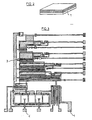
- Figure 1 shows schematically the operating diagram of a microwave thermography radiometer.
- the measurement of the internal temperature of a body not shown is carried out by means of an antenna 1 placed on said body and which picks up the thermal radiation emitted by said body.
- This thermal radiation is proportional to the body temperature and moreover the antenna picks up the signals transmitted according to a certain volume which corresponds to an internal part of the body, which makes it possible to carry out a depth measurement of the order of a few centimeters. of the temperature.
- a standard noise source 4 generally constituted by a resistor also delivers a signal 5 proportional to the temperature of said source 4.
- Source 4 is also connected to an indicator, as shown in Figure 1, which displays the temperature.
- This signal 5 is also directed to the amplifier 3 via a two-way switch 6 which, in turn, connects the input 7 of the amplifier 3 to the antenna 1 or to the noise source 4 so as to supply the l amplifier with signal 2, sometimes with signal 5.
- the two-way switch 6 is controlled by a generator BF 8 which delivers a frequency F o to the switch 6.
- the signal 9 at the output of amplifier 3 is directed to a detector. 1 which indicates to the manipulator whether there is equality between the temperatures measured by the antenna 1 and the temperature of the standard source 4. It thus appears that the signal 9 at the amplifier output corresponds to an “error” signal that the operator must try to cancel by adjusting the heating of the standard noise resistance 4 to equalize it with the body temperature whose thermal radiation is captured using the antenna 1.
- the synchronous detector 11 delivers a signal 12 directly proportional to the temperature difference presented between the body examined and the standard noise resistance which allows, using a heating control circuit 13, to adjust the temperature of the standard noise resistance 4 to obtain a zero error signal 9.
- the noise temperature of the amplifier depends on the impedance of the input device and it is therefore essential that the resistance of the antenna is equal to that of the noise resistance.
- an additional impedance is placed alternately in parallel sometimes with the antenna 1, sometimes with the standard source 4 and the influence exerted by the additional impedance on the antenna and on is compared.
- the noise source so as to adjust the antenna or the noise source to equalize these influences and consequently the impedances presented by the antenna and the standard noise resistance 4.
- an impedance matching control circuit 14 is placed at the input of the amplifier 3 which sometimes places an impedance 15 at the input of the amplifier 3 sometimes places itself in open circuit 16. So periodically, an additional impedance 15 is placed at the input of the amplifier 3.
- the impedance control circuit is controlled by a generator BF 17 which delivers a signal of frequency F1 which ensures the switching of the impedance 15 and the open circuit 16.
- This input signal 7 is analyzed by a synchronous detector 18, controlled by the LF generator 17, which delivers a signal 19.
- the frequency F 1 is desirable for the frequency F 1 to be significantly higher than the frequency F o delivered by the generator 8.
- the signal 19 is directly portable away from the impedances presented by the antenna 1 and the standard noise resistance 4. Consequently, this signal 19, in order to optimize the process, can be directed to an adjustment circuit 20 of the impedance adaptation presented by the noise standard resistance 4 so as to adjust the latter with that presented by the antenna 1.
- the adaptation control circuit 14 is presented as a switch controlled by an alternating voltage of frequency F1 which makes it possible to alternately put in parallel on the input of the microwave amplifier 3 an additional capacitance or resistance.
- This modifies the input impedance seen by the amplifier in alternation, including the noise temperature T R, but it should be noted that this modification of impedance or of the noise temperature T R will not necessarily be the same as the antenna or the noise resistance is connected to the input of the amplifier and it is only in the case where the noise resistance 4 and the antenna 1 have the same impedance that the modification of impedance will be identical. It is therefore sufficient to detect at the amplifier output the alternating signal of frequency F1 to obtain an error signal proportional to the difference in impedance between the noise resistance 4 and that of the antenna 1. The signal error can then be used to modify the value of the noise resistance so that it remains equal to that of the antenna or more simply when it is beyond a certain threshold to send a message to the experimenter indicating that the antenna is badly adapted.
- This impedance matching control method which can be applied to any low noise reception chain was used for the manufacture of a miniature microwave thermometer according to the invention.
- the miniature microwave thermometer is produced according to the diagrams illustrated in FIGS. 2 and 3. It is a thermometer produced with an integrated circuit in monolithic technology which uses the epitaxial layers n + n on semi-insulator produced in semiconductor of type III-V such as for example in AsGa.
- the antenna 1 is placed at the bottom of the circuit. The whole is thus designed in an integrated manner.
- the basic active element consists of field effect transistors using a Schottky contact grid.
- the resistance forming the standard noise source will preferably be produced in planar form consisting of an epitaxial layer between two ohmic contacts.
- the heating control 13 which makes it possible to modify the temperature of the standard noise source 4 is preferably carried out by means of heating resistors framing or arranged in the immediate vicinity of the noise resistance.
- the distance will be of the order of a few microns.
- the device for measuring the temperature of the standard noise source 4 uses the variations, as a function of the temperature, of the voltage current characteristic of a semiconductor metal contact.
- the device for controlling the value of the standard noise resistance 4 uses the modification of the thickness of the resistance layer from a Schottky contact grid, the applied voltage of which is varied.
- the microwave amplifier 3 illustrated in FIG. 3 must have a maximum bandwidth and on the other hand be of design as simple as possible.
- the solution envisaged to achieve this objective is to use a common source assembly and to connect the drain to the grid of the next stage by a simple connection capacity.
- One of the most important factors which limits the bandwidth of this configuration is the fact that the input (capacitive) admittance of a given stage in the amplification chain becomes when the frequency increases greater than the admittance of (conductive) exit from the previous floor.
- the cutoff frequency is therefore of the form: where g di is the output admittance of stage i and C di + 1 the input capacity of stage i + 1.
- the solution proposed by the present invention is to use transistors with decreasing dimension (width) field effect. In this way, the input capacity and the output conductance being proportional to this width, the cut-off frequency can therefore be increased.
Landscapes
- Physics & Mathematics (AREA)
- General Physics & Mathematics (AREA)
- Engineering & Computer Science (AREA)
- Power Engineering (AREA)
- Electromagnetism (AREA)
- Radiation Pyrometers (AREA)
Claims (12)
Applications Claiming Priority (2)
| Application Number | Priority Date | Filing Date | Title |
|---|---|---|---|
| FR8404792 | 1984-03-21 | ||
| FR8404792A FR2561769B1 (fr) | 1984-03-21 | 1984-03-21 | Procede de controle d'adaptation d'impedance dans les chaines de reception faible bruit et thermometre micro-onde miniature de mise en oeuvre du procede |
Publications (2)
| Publication Number | Publication Date |
|---|---|
| EP0159279A1 EP0159279A1 (de) | 1985-10-23 |
| EP0159279B1 true EP0159279B1 (de) | 1989-06-07 |
Family
ID=9302533
Family Applications (1)
| Application Number | Title | Priority Date | Filing Date |
|---|---|---|---|
| EP85440017A Expired EP0159279B1 (de) | 1984-03-21 | 1985-03-13 | Verfahren zur Kontrolle der Impedanzanpassung in rauscharmen Empfängerschaltungen und Miniaturmikrowellenthermometer nach diesem Verfahren |
Country Status (4)
| Country | Link |
|---|---|
| US (1) | US4677988A (de) |
| EP (1) | EP0159279B1 (de) |
| DE (1) | DE3570928D1 (de) |
| FR (1) | FR2561769B1 (de) |
Families Citing this family (12)
| Publication number | Priority date | Publication date | Assignee | Title |
|---|---|---|---|---|
| DE3601983A1 (de) * | 1986-01-23 | 1987-07-30 | Siemens Ag | Verfahren und vorrichtung zur beruehrungslosen bestimmung der temperaturverteilung in einem untersuchungsobjekt |
| DE3637549A1 (de) * | 1986-11-04 | 1988-05-11 | Hans Dr Med Rosenberger | Messgeraet zur pruefung der dielektrischen eigenschaften biologischer gewebe |
| FR2650390B1 (fr) * | 1989-07-27 | 1992-10-30 | Inst Nat Sante Rech Med | Procede pour la mesure des temperatures par radiometrie microonde, avec calibration automatique de la mesure, et dispositif pour la mise en oeuvre de ce procede |
| FR2673470B1 (fr) * | 1991-02-01 | 1993-06-04 | Centre Nat Rech Scient | Procede, dispositif de mesure de temperature utilisant le rayonnement microonde et application pour la determination du coefficient de reflexion hyperfrequence d'un objet quelconque. |
| US5149198A (en) * | 1991-05-02 | 1992-09-22 | Mmtc, Inc. | Temperature-measuring microwave radiometer apparatus |
| SE501473C2 (sv) * | 1993-02-03 | 1995-02-27 | Stiftelsen Metallurg Forsk | Sätt att bestämma gasers och flammors tillstånd i smält och förbränningsprocesser |
| FR2705441B1 (fr) * | 1993-05-14 | 1995-08-18 | Seb Sa | Procédé et dispositif de détermination d'un état de cuisson d'un aliment dans une enceinte fermée. |
| EP1224905A3 (de) * | 2001-01-17 | 2002-07-31 | The Minister Of National Defence Of Her Majesty's Canadian Government | Nicht-invasives System zur dreidimensionsalen intrakraniellen Thermographie |
| US6834991B2 (en) * | 2002-09-23 | 2004-12-28 | Raytheon Company | Radiometer with programmable noise source calibration |
| RU2005104613A (ru) * | 2005-02-22 | 2006-08-10 | Открытое акционерное общество "Система-Венчур" (RU) | Микроволновый радиотермотомограф |
| DE102007019403B4 (de) * | 2007-04-23 | 2009-05-14 | Miele & Cie. Kg | Temperaturmesssonde, insbesondere für ein Haushaltsgerät |
| CN111133682B (zh) * | 2017-05-05 | 2022-06-10 | 意法半导体有限公司 | 用于控制天线与传输路径的匹配的方法及对应设备 |
Family Cites Families (10)
| Publication number | Priority date | Publication date | Assignee | Title |
|---|---|---|---|---|
| US3564420A (en) * | 1967-11-28 | 1971-02-16 | Nasa | Method and means for providing an absolute power measurement capability |
| US3777270A (en) * | 1972-05-12 | 1973-12-04 | Rockwell International Corp | Precision variable pulse rate nulling radiometer |
| CA1061433A (en) * | 1976-04-07 | 1979-08-28 | Michael A. Hamid | Counting agricultural products |
| US4190053A (en) * | 1977-06-20 | 1980-02-26 | Rca Corporation | Apparatus and method for hyperthermia treatment |
| US4228809A (en) * | 1977-10-06 | 1980-10-21 | Rca Corporation | Temperature controller for a microwave heating system |
| DE2803480C2 (de) * | 1978-01-27 | 1984-11-22 | Philips Patentverwaltung Gmbh, 2000 Hamburg | Verfahren und Anordnung zur Messung der physikalischen Objekttemperatur mittels Mikrowellen |
| US4178100A (en) * | 1978-03-29 | 1979-12-11 | Nasa | Distributed-switch Dicke radiometers |
| SU799726A1 (ru) * | 1978-08-18 | 1981-01-30 | Предприятие П/Я А-7866 | Устройство дл обнаружени темпе-РАТуРНыХ АНОМАлий |
| FR2497947A1 (fr) * | 1981-01-09 | 1982-07-16 | Technologie Biomedicale Centre | Procede et dispositif de thermographie-hyperthermie en micro-ondes |
| GB2106394B (en) * | 1981-09-24 | 1986-03-19 | Richard Hugh Cameron Bentall | Device for applying a high frequency electromagnetic field to living tissue to promote healing thereof |
-
1984
- 1984-03-21 FR FR8404792A patent/FR2561769B1/fr not_active Expired
-
1985
- 1985-03-13 DE DE8585440017T patent/DE3570928D1/de not_active Expired
- 1985-03-13 EP EP85440017A patent/EP0159279B1/de not_active Expired
- 1985-03-21 US US06/714,700 patent/US4677988A/en not_active Expired - Fee Related
Also Published As
| Publication number | Publication date |
|---|---|
| DE3570928D1 (en) | 1989-07-13 |
| FR2561769A1 (fr) | 1985-09-27 |
| US4677988A (en) | 1987-07-07 |
| FR2561769B1 (fr) | 1986-08-22 |
| EP0159279A1 (de) | 1985-10-23 |
Similar Documents
| Publication | Publication Date | Title |
|---|---|---|
| EP2135050B1 (de) | Radiometrisches thermometer | |
| EP0159279B1 (de) | Verfahren zur Kontrolle der Impedanzanpassung in rauscharmen Empfängerschaltungen und Miniaturmikrowellenthermometer nach diesem Verfahren | |
| EP0645626B1 (de) | Messvorrichtung für entfernbare Sensoren | |
| EP0260321B1 (de) | Verfahren zur prüfung der elektrisch aktiven unreinheiten von halbleitermaterial oder strukturen sowie messanordnung dazu | |
| FR2468879A1 (fr) | Sonde et dispositif pour en detecter le delogement | |
| FR2992067A1 (fr) | Procede et dispositif d'ajustement de la tension de polarisation d'une photodiode spad | |
| EP2246677A1 (de) | Bolometrischer Detektor für elektromagnetische Strahlung im Spektralbereich von Infrarot bis Terahertz und Detektoranordnung mit solchen Detektoren. | |
| JPS6328045A (ja) | 半導体ウエファの温度を測定する装置および方法 | |
| EP3042446A1 (de) | Verfahren zur automatischen impedanzanpassung und entsprechender übertragungskanal | |
| FR3067809A1 (fr) | Dispositifs de jauge a vide micro-fabriques sans etalonnage et procede de mesure de pression | |
| EP0187562A1 (de) | Durchflussmesser mit einem temperaturempfindlichen Widerstandselement | |
| EP0523221B1 (de) | Verfahren zum messen der temperatur eines materials unter verwendung von mikrowellenstrahlung | |
| FR2738693A1 (fr) | Systeme de traitement d'impulsions provenant de l'interaction d'une particule gamma avec un detecteur de rayonnement cdte | |
| EP1387155A1 (de) | Miniaturverbinder mit integrierter Elektronik für Thermoelement | |
| EP3067704A1 (de) | Vorrichtung zum messen eines elektrischen felds in einem leitermilieu, und kalibrierverfahren dieser vorrichtung | |
| FR2656690A1 (fr) | Procede et appareil de mesure de la temperature d'une pastille semi-conductrice par detection de la transmission optique. | |
| Nakagawa et al. | Characteristics of high-sensitivity Ge bolometer | |
| FR3108172A1 (fr) | Radiometre et son application a la mesure de temperature | |
| EP1226443B1 (de) | Sensor für elektromagnetische wellen | |
| EP2567245B1 (de) | Vorrichtung zum messen des lokalen elektrischen widerstand einer oberfläche | |
| EP3987280A1 (de) | Verfahren zur detektion mindestens einer gasmenge mindestens eines vorbestimmten gases durch einen messfühler einer mehrzahl von gasen | |
| FR3066826B1 (fr) | Procede de caracterisation electrique de transistor mos sur soi | |
| FR2621396A1 (fr) | Appareil de mesure de l'impedance electrique | |
| FR2511809A1 (fr) | Circuit a semi-conducteurs devant fonctionner, notamment en tant qu'amplificateur differentiel, sur une certaine plage de temperatures, et son procede d'utilisation | |
| FR3085485A1 (fr) | Procede de test de fiabilite d'un composant electronique |
Legal Events
| Date | Code | Title | Description |
|---|---|---|---|
| PUAI | Public reference made under article 153(3) epc to a published international application that has entered the european phase |
Free format text: ORIGINAL CODE: 0009012 |
|
| AK | Designated contracting states |
Designated state(s): DE GB NL |
|
| 17P | Request for examination filed |
Effective date: 19860422 |
|
| 17Q | First examination report despatched |
Effective date: 19880408 |
|
| GRAA | (expected) grant |
Free format text: ORIGINAL CODE: 0009210 |
|
| AK | Designated contracting states |
Kind code of ref document: B1 Designated state(s): DE GB NL |
|
| REF | Corresponds to: |
Ref document number: 3570928 Country of ref document: DE Date of ref document: 19890713 |
|
| GBT | Gb: translation of ep patent filed (gb section 77(6)(a)/1977) | ||
| PLBE | No opposition filed within time limit |
Free format text: ORIGINAL CODE: 0009261 |
|
| STAA | Information on the status of an ep patent application or granted ep patent |
Free format text: STATUS: NO OPPOSITION FILED WITHIN TIME LIMIT |
|
| 26N | No opposition filed | ||
| PGFP | Annual fee paid to national office [announced via postgrant information from national office to epo] |
Ref country code: NL Payment date: 19950331 Year of fee payment: 11 |
|
| PGFP | Annual fee paid to national office [announced via postgrant information from national office to epo] |
Ref country code: GB Payment date: 19960304 Year of fee payment: 12 |
|
| PGFP | Annual fee paid to national office [announced via postgrant information from national office to epo] |
Ref country code: DE Payment date: 19960312 Year of fee payment: 12 |
|
| PG25 | Lapsed in a contracting state [announced via postgrant information from national office to epo] |
Ref country code: NL Effective date: 19961001 |
|
| NLV4 | Nl: lapsed or anulled due to non-payment of the annual fee |
Effective date: 19961001 |
|
| PG25 | Lapsed in a contracting state [announced via postgrant information from national office to epo] |
Ref country code: GB Effective date: 19970313 |
|
| GBPC | Gb: european patent ceased through non-payment of renewal fee |
Effective date: 19970313 |
|
| PG25 | Lapsed in a contracting state [announced via postgrant information from national office to epo] |
Ref country code: DE Effective date: 19971202 |