EP0159279B1 - Method for the control of the impedance match in low-noise receiver circuits, and miniature microwave thermometer utilizing this method - Google Patents
Method for the control of the impedance match in low-noise receiver circuits, and miniature microwave thermometer utilizing this method Download PDFInfo
- Publication number
- EP0159279B1 EP0159279B1 EP85440017A EP85440017A EP0159279B1 EP 0159279 B1 EP0159279 B1 EP 0159279B1 EP 85440017 A EP85440017 A EP 85440017A EP 85440017 A EP85440017 A EP 85440017A EP 0159279 B1 EP0159279 B1 EP 0159279B1
- Authority
- EP
- European Patent Office
- Prior art keywords
- noise
- source
- impedance
- aerial
- standard
- Prior art date
- Legal status (The legal status is an assumption and is not a legal conclusion. Google has not performed a legal analysis and makes no representation as to the accuracy of the status listed.)
- Expired
Links
- 238000000034 method Methods 0.000 title claims description 26
- 230000006978 adaptation Effects 0.000 claims description 14
- 230000005855 radiation Effects 0.000 claims description 13
- 238000010438 heat treatment Methods 0.000 claims description 8
- 238000012986 modification Methods 0.000 claims description 7
- 230000004048 modification Effects 0.000 claims description 7
- 238000001931 thermography Methods 0.000 claims description 6
- 230000005669 field effect Effects 0.000 claims description 5
- 230000001360 synchronised effect Effects 0.000 claims description 5
- 239000004065 semiconductor Substances 0.000 claims description 4
- JBRZTFJDHDCESZ-UHFFFAOYSA-N AsGa Chemical compound [As]#[Ga] JBRZTFJDHDCESZ-UHFFFAOYSA-N 0.000 claims description 2
- 229910017214 AsGa Inorganic materials 0.000 claims description 2
- 239000002184 metal Substances 0.000 claims description 2
- 230000000694 effects Effects 0.000 claims 3
- 238000001514 detection method Methods 0.000 claims 2
- 239000003990 capacitor Substances 0.000 claims 1
- 230000001276 controlling effect Effects 0.000 claims 1
- 239000000463 material Substances 0.000 claims 1
- 230000001105 regulatory effect Effects 0.000 claims 1
- 238000005259 measurement Methods 0.000 description 9
- 238000010586 diagram Methods 0.000 description 4
- 230000036760 body temperature Effects 0.000 description 3
- 238000004519 manufacturing process Methods 0.000 description 3
- 230000008901 benefit Effects 0.000 description 2
- 230000003321 amplification Effects 0.000 description 1
- 238000004458 analytical method Methods 0.000 description 1
- 230000003247 decreasing effect Effects 0.000 description 1
- 238000013461 design Methods 0.000 description 1
- 238000005516 engineering process Methods 0.000 description 1
- 238000002474 experimental method Methods 0.000 description 1
- 238000009432 framing Methods 0.000 description 1
- 239000012212 insulator Substances 0.000 description 1
- 238000003199 nucleic acid amplification method Methods 0.000 description 1
- 230000000737 periodic effect Effects 0.000 description 1
- 230000006641 stabilisation Effects 0.000 description 1
- 238000011105 stabilization Methods 0.000 description 1
Images

Classifications
-
- G—PHYSICS
- G01—MEASURING; TESTING
- G01K—MEASURING TEMPERATURE; MEASURING QUANTITY OF HEAT; THERMALLY-SENSITIVE ELEMENTS NOT OTHERWISE PROVIDED FOR
- G01K11/00—Measuring temperature based upon physical or chemical changes not covered by groups G01K3/00, G01K5/00, G01K7/00 or G01K9/00
- G01K11/006—Measuring temperature based upon physical or chemical changes not covered by groups G01K3/00, G01K5/00, G01K7/00 or G01K9/00 using measurement of the effect of a material on microwaves or longer electromagnetic waves, e.g. measuring temperature via microwaves emitted by the object
-
- G—PHYSICS
- G01—MEASURING; TESTING
- G01R—MEASURING ELECTRIC VARIABLES; MEASURING MAGNETIC VARIABLES
- G01R21/00—Arrangements for measuring electric power or power factor
- G01R21/02—Arrangements for measuring electric power or power factor by thermal methods, e.g. calorimetric
- G01R21/04—Arrangements for measuring electric power or power factor by thermal methods, e.g. calorimetric in circuits having distributed constants
Definitions
- the invention relates to a method for calibrating and controlling impedance matching for low noise reception chains for microwave noise measurement device.
- the invention will particularly find its application in microwave thermography produced in a monolithic integrated circuit for measuring internal body temperature.
- thermograph for depth measurement, of the order of a few centimeters, of temperature, is well known. It is a device comprising in particular an antenna intended to capture the thermal radiation emitted by a certain volume of the body to be examined.
- the microwave signal picked up by the antenna resulting from the thermal radiation of the object to be analyzed which is proportional to the temperature of said object, is compared alternately with a signal coming from a standard noise resistance of temperature constantly monitored and measured.
- a switch controlled by an alternating LF signal makes it possible to alternately “connect” to the input of a microwave amplifier the signal coming from the noise resistance or that coming from the microwave antenna.
- the AC signal received and detected at the amplifier output is thus proportional to the temperature difference between that of the object to be measured and that of the noise source.
- This signal can therefore constitute an error signal making it possible to adjust the temperature setting of the standard noise resistance so as to obtain equality of the two temperatures. It then suffices to read the temperature of the noise standard resistance to obtain that of the object to be measured.
- the noise temperature of the amplifier depends on the impedance of the input device and it is therefore essential that the resistance of the antenna is equal to that of the noise resistance.
- This device is based on a traditional zero method and we recover the noise by means of the antenna and then compare this noise to a reference. After stabilization, it is concluded that the value of the reference corresponds to the value of the temperature of the object considered.
- the object of the present invention is to present a method of controlling impedance adaptation for a low noise reception chain such as radiometers used in microwave thermography which makes it possible to ensure at all times the exact correspondence between the impedance presented by the antenna and the impedance presented by the standard noise source.
- the comparison of the impedances is carried out continuously throughout the experiment, this results in a high reliability of the results of the measurement.
- the electrical circuit for implementing the method immediately adjusts the impedance presented by the standard noise source in order to adjust the latter with respect to the antenna impedance.
- Another object of the present invention is to present a miniature microwave thermometer for implementing the method of the present invention.
- This miniature thermometer is in the form of a monolithic integrated circuit and therefore it has an extremely small footprint.
- the microwave amplifier used has a special manufacturing architecture which allows it to benefit from a very wide bandwidth with a cut-off frequency greatly increased compared to traditional embodiments.
- the method of calibration and control of impedance adaptation for low noise reception chains finding in particular its application in microwave thermography for the measurement of internal temperature of a body, method in which:
- the thermal radiation of the body to be examined is captured using an antenna
- the signal received by the antenna is compared with the signal emitted by a standard noise source, adjustable in temperature, is characterized in that:
- the signals received by the antenna and the signals coming from the standard noise source are directed alternately to the input of an amplifier through switching means, controlled by a frequency F o ,
- an additional impedance is placed at the input of the amplifier, alternatively and periodically at a frequency F i , in parallel either with the antenna or with the standard noise source, the frequency F 1 being clearly greater than the frequency F o ,
- the influence exerted by the additional impedance on the antenna and on the standard noise source is compared, by detecting the modification of the input signal of the amplifier and by analyzing the difference in the impedances respectively presented by the antenna and standard noise source,
- the microwave noise measuring device implementing the method of the present invention comprises at least:
- an antenna capable of picking up microwave radiation, and of delivering a corresponding output signal
- a standard noise source adjustable in temperature via a heating control circuit, capable of delivering a signal corresponding to the temperature of said source
- an amplifier the input of which is at least connected to the output of said switching means, outputting an amplitude signal corresponding to the level difference between said signals delivered respectively by the antenna and by the standard noise source,
- an additional impedance capable of being placed periodically on the input of the amplifier in parallel with the impedance presented either by the antenna or by the noise source at the input of the amplifier,
- the present invention relates to an impedance matching control method for a low noise reception chain and a miniature microwave thermometer.
- the description of the process is applied to microwave thermography, however, the invention can be applied to any measuring device using as a principle of analysis the comparison of the signals emitted by a reference source and the source to be studied.
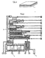
- Figure 1 shows schematically the operating diagram of a microwave thermography radiometer.
- the measurement of the internal temperature of a body not shown is carried out by means of an antenna 1 placed on said body and which picks up the thermal radiation emitted by said body.
- This thermal radiation is proportional to the body temperature and moreover the antenna picks up the signals transmitted according to a certain volume which corresponds to an internal part of the body, which makes it possible to carry out a depth measurement of the order of a few centimeters. of the temperature.
- a standard noise source 4 generally constituted by a resistor also delivers a signal 5 proportional to the temperature of said source 4.
- Source 4 is also connected to an indicator, as shown in Figure 1, which displays the temperature.
- This signal 5 is also directed to the amplifier 3 via a two-way switch 6 which, in turn, connects the input 7 of the amplifier 3 to the antenna 1 or to the noise source 4 so as to supply the l amplifier with signal 2, sometimes with signal 5.
- the two-way switch 6 is controlled by a generator BF 8 which delivers a frequency F o to the switch 6.
- the signal 9 at the output of amplifier 3 is directed to a detector. 1 which indicates to the manipulator whether there is equality between the temperatures measured by the antenna 1 and the temperature of the standard source 4. It thus appears that the signal 9 at the amplifier output corresponds to an “error” signal that the operator must try to cancel by adjusting the heating of the standard noise resistance 4 to equalize it with the body temperature whose thermal radiation is captured using the antenna 1.
- the synchronous detector 11 delivers a signal 12 directly proportional to the temperature difference presented between the body examined and the standard noise resistance which allows, using a heating control circuit 13, to adjust the temperature of the standard noise resistance 4 to obtain a zero error signal 9.
- the noise temperature of the amplifier depends on the impedance of the input device and it is therefore essential that the resistance of the antenna is equal to that of the noise resistance.
- an additional impedance is placed alternately in parallel sometimes with the antenna 1, sometimes with the standard source 4 and the influence exerted by the additional impedance on the antenna and on is compared.
- the noise source so as to adjust the antenna or the noise source to equalize these influences and consequently the impedances presented by the antenna and the standard noise resistance 4.
- an impedance matching control circuit 14 is placed at the input of the amplifier 3 which sometimes places an impedance 15 at the input of the amplifier 3 sometimes places itself in open circuit 16. So periodically, an additional impedance 15 is placed at the input of the amplifier 3.
- the impedance control circuit is controlled by a generator BF 17 which delivers a signal of frequency F1 which ensures the switching of the impedance 15 and the open circuit 16.
- This input signal 7 is analyzed by a synchronous detector 18, controlled by the LF generator 17, which delivers a signal 19.
- the frequency F 1 is desirable for the frequency F 1 to be significantly higher than the frequency F o delivered by the generator 8.
- the signal 19 is directly portable away from the impedances presented by the antenna 1 and the standard noise resistance 4. Consequently, this signal 19, in order to optimize the process, can be directed to an adjustment circuit 20 of the impedance adaptation presented by the noise standard resistance 4 so as to adjust the latter with that presented by the antenna 1.
- the adaptation control circuit 14 is presented as a switch controlled by an alternating voltage of frequency F1 which makes it possible to alternately put in parallel on the input of the microwave amplifier 3 an additional capacitance or resistance.
- This modifies the input impedance seen by the amplifier in alternation, including the noise temperature T R, but it should be noted that this modification of impedance or of the noise temperature T R will not necessarily be the same as the antenna or the noise resistance is connected to the input of the amplifier and it is only in the case where the noise resistance 4 and the antenna 1 have the same impedance that the modification of impedance will be identical. It is therefore sufficient to detect at the amplifier output the alternating signal of frequency F1 to obtain an error signal proportional to the difference in impedance between the noise resistance 4 and that of the antenna 1. The signal error can then be used to modify the value of the noise resistance so that it remains equal to that of the antenna or more simply when it is beyond a certain threshold to send a message to the experimenter indicating that the antenna is badly adapted.
- This impedance matching control method which can be applied to any low noise reception chain was used for the manufacture of a miniature microwave thermometer according to the invention.
- the miniature microwave thermometer is produced according to the diagrams illustrated in FIGS. 2 and 3. It is a thermometer produced with an integrated circuit in monolithic technology which uses the epitaxial layers n + n on semi-insulator produced in semiconductor of type III-V such as for example in AsGa.
- the antenna 1 is placed at the bottom of the circuit. The whole is thus designed in an integrated manner.
- the basic active element consists of field effect transistors using a Schottky contact grid.
- the resistance forming the standard noise source will preferably be produced in planar form consisting of an epitaxial layer between two ohmic contacts.
- the heating control 13 which makes it possible to modify the temperature of the standard noise source 4 is preferably carried out by means of heating resistors framing or arranged in the immediate vicinity of the noise resistance.
- the distance will be of the order of a few microns.
- the device for measuring the temperature of the standard noise source 4 uses the variations, as a function of the temperature, of the voltage current characteristic of a semiconductor metal contact.
- the device for controlling the value of the standard noise resistance 4 uses the modification of the thickness of the resistance layer from a Schottky contact grid, the applied voltage of which is varied.
- the microwave amplifier 3 illustrated in FIG. 3 must have a maximum bandwidth and on the other hand be of design as simple as possible.
- the solution envisaged to achieve this objective is to use a common source assembly and to connect the drain to the grid of the next stage by a simple connection capacity.
- One of the most important factors which limits the bandwidth of this configuration is the fact that the input (capacitive) admittance of a given stage in the amplification chain becomes when the frequency increases greater than the admittance of (conductive) exit from the previous floor.
- the cutoff frequency is therefore of the form: where g di is the output admittance of stage i and C di + 1 the input capacity of stage i + 1.
- the solution proposed by the present invention is to use transistors with decreasing dimension (width) field effect. In this way, the input capacity and the output conductance being proportional to this width, the cut-off frequency can therefore be increased.
Description
L'invention est relative à un procédé d'étalonnage et de contrôle d'adaptation d'impédance pour chaînes de réception faible bruit pour dispositif de mesure de bruit micro-onde. L'invention trouvera particulièrement son application en thermographie micro-onde réalisé en circuit intégré monolithique pour la mesure de température interne de corps.The invention relates to a method for calibrating and controlling impedance matching for low noise reception chains for microwave noise measurement device. The invention will particularly find its application in microwave thermography produced in a monolithic integrated circuit for measuring internal body temperature.
Le principe du thermographe micro-onde pour la mesure en profondeur, de l'ordre de quelques centimètres, de température, est bien connu. Il s'agit d'un appareil comprenant notamment une antenne destinée à capter le rayonnement thermique émis par un certain volume du corps à examiner.The principle of the microwave thermograph for depth measurement, of the order of a few centimeters, of temperature, is well known. It is a device comprising in particular an antenna intended to capture the thermal radiation emitted by a certain volume of the body to be examined.
Il est connu qu'il existe une relation directe entre le signal micro-onde émis et la température interne du corps.It is known that there is a direct relationship between the microwave signal emitted and the internal temperature of the body.
Plusieurs dispositifs de ce type ont été mis au point tel que le radiomètre de Dicke pour permettre d'analyser le rayonnement thermique.Several devices of this type have been developed, such as the Dicke radiometer to analyze thermal radiation.
En général, le principe utilisé peut être résumé de la façon suivante. Le signal hyperfréquence capté par l'antenne résultant du rayonnement thermique de l'objet à analyser, qui est proportionnel à la température dudit objet, est comparé alternativement à un signal provenant d'une résistance de bruit étalon de température constamment contrôlée et mesurée.In general, the principle used can be summarized as follows. The microwave signal picked up by the antenna resulting from the thermal radiation of the object to be analyzed, which is proportional to the temperature of said object, is compared alternately with a signal coming from a standard noise resistance of temperature constantly monitored and measured.
A cet effet, un commutateur commandé par un signal BF alternatif permet de « brancher » alternativement à l'entrée d'un amplificateur hyperfréquence le signal provenant de la résistance de bruit ou celui provenant de l'antenne hyperfréquence.To this end, a switch controlled by an alternating LF signal makes it possible to alternately “connect” to the input of a microwave amplifier the signal coming from the noise resistance or that coming from the microwave antenna.
Le signal alternatif reçu et détecté à la sortie de l'amplificateur est ainsi proportionnel à la différence de température entre celle de l'objet à mesure et celle de la source de bruit. Ce signal peut donc constituer un signal d'erreur permettant d'ajuster le réglage de la température de la résistance de bruit étalon de façon à obtenir l'égalité des deux températures. Il suffit alors de lire la température de la résistance étalon de bruit pour obtenir celle de l'objet à mesurer.The AC signal received and detected at the amplifier output is thus proportional to the temperature difference between that of the object to be measured and that of the noise source. This signal can therefore constitute an error signal making it possible to adjust the temperature setting of the standard noise resistance so as to obtain equality of the two temperatures. It then suffices to read the temperature of the noise standard resistance to obtain that of the object to be measured.
Il faut toutefois noter que pour obtenir une mesure précise de la témpérature de l'objet, il est nécessaire de connaître avec exactitude l'impédance présentée par l'antenne captant le rayonnement thermique et d'ajuster de façon rigoureuse celle de la résistance de bruit dont la température devra être réglée et contrôlée de façon rigoureuse.It should however be noted that to obtain an accurate measurement of the temperature of the object, it is necessary to know exactly the impedance presented by the antenna receiving the thermal radiation and to rigorously adjust that of the noise resistance whose temperature must be rigorously set and controlled.
En effet, la température de bruit de l'amplificateur dépend de l'impédance du dispositif d'entrée et il est donc essentiel que la résistance de l'antenne soit égale à celle de la résistance de bruit.Indeed, the noise temperature of the amplifier depends on the impedance of the input device and it is therefore essential that the resistance of the antenna is equal to that of the noise resistance.
A l'heure actuelle, cette mesure est extrêmement délicate et nécessite une manipulation préalable particulièrement fastidieuse.Currently, this measurement is extremely delicate and requires particularly tedious prior manipulation.
A cet égard, il est connu du document FR-A-2 415 799 un. dispositif pour la mesure de la température physique d'un objet à l'aide de micro-onde qui utilise un radiomètre de Dicke et une antenne orientée sur l'objet.In this regard, it is known from document FR-A-2 415 799 a. device for measuring the physical temperature of an object using a microwave which uses a Dicke radiometer and an antenna oriented on the object.
Ce dispositif est basé sur une méthode de zéro traditionnelle et on récupère le bruit au moyen de l'antenne puis on compare ce bruit à une référence. Après stabilisation, on conclut que la valeur de la référence correspond à la valeur de la température de l'objet considéré.This device is based on a traditional zero method and we recover the noise by means of the antenna and then compare this noise to a reference. After stabilization, it is concluded that the value of the reference corresponds to the value of the temperature of the object considered.
Cependant, un tel dispositif présente les inconvénients précités.However, such a device has the aforementioned drawbacks.
Le but de la présente invention est de présenter un procédé de contrôle d'adaptation d'impédance pour chaîne de réception faible bruit telle que les radiomètres utilisés en thermographie micro- onde qui permet de s'assurer à tout instant de la correspondance exacte entre l'impédance présentée par l'antenne et l'impédance présentée par la source de bruit étalon.The object of the present invention is to present a method of controlling impedance adaptation for a low noise reception chain such as radiometers used in microwave thermography which makes it possible to ensure at all times the exact correspondence between the impedance presented by the antenna and the impedance presented by the standard noise source.
Selon l'invention, la comparaison des impédances est réalisée en permanence tout au long de l'expérience, il en résulte une grande fiabilité des résultats de la mesure.According to the invention, the comparison of the impedances is carried out continuously throughout the experiment, this results in a high reliability of the results of the measurement.
Par ailleurs, selon un mode préférentiel de mise en oeuvre du procédé de l'invention, en cas de variation d'une impédance par rapport à l'autre, le circuit électrique de mise en oeuvre du procédé ajuste immédiatement l'impédance présentée par la source étalon de bruit afin d'ajuster cette dernière par rapport à l'impédance de l'antenne.Furthermore, according to a preferred embodiment of the method of the invention, in the event of a variation of one impedance with respect to the other, the electrical circuit for implementing the method immediately adjusts the impedance presented by the standard noise source in order to adjust the latter with respect to the antenna impedance.
Il en résulte une grande simplification d'utilisation pour le manipulateur qui n'a plus à se préoccuper au cours de l'expérience de l'adaptation des différentes impédances, celles-ci étant corrigées automatiquement.This results in a great simplification of use for the manipulator who no longer has to worry during the experience of adapting the different impedances, these being corrected automatically.
Il faut par ailleurs souligner que si, par erreur, l'antenne de réception du rayonnement thermique était mal disposée et que celle-ci présentait une impédance mal adaptée, le manipulateur pourrait en être immédiatement averti et effectuer les réglages qui s'imposent.It should also be pointed out that if, by mistake, the antenna for receiving the thermal radiation was improperly placed and that it had an improperly adapted impedance, the manipulator could be immediately notified and make the necessary adjustments.
Un autre but de la présente invention est de présenter un thermomètre micro-onde miniature pour la mise en oeuvre du procédé de la présente invention. Ce thermomètre miniature se présente sous la forme d'un circuit intégré monolithique et par conséquent il bénéficie d'un encombrement extrêmement réduit.Another object of the present invention is to present a miniature microwave thermometer for implementing the method of the present invention. This miniature thermometer is in the form of a monolithic integrated circuit and therefore it has an extremely small footprint.
Par ailleurs, l'ensemble des composants y compris l'antenne auront pu être concentrés sur un même circuit grâce à une mise en oeuvre technologique particulière.Furthermore, all of the components including the antenna could have been concentrated on the same circuit thanks to a particular technological implementation.
En outre, l'amplificateur hyperfréquence utilisé jouit d'une architecture de fabrication spéciale qui lui permet de bénéficier d'une très large bande passante avec une fréquence de coupure largement augmentée vis-à-vis des réalisations traditionnelles.In addition, the microwave amplifier used has a special manufacturing architecture which allows it to benefit from a very wide bandwidth with a cut-off frequency greatly increased compared to traditional embodiments.
D'autres buts et avantages de la présente invention apparaîtront au cours de la description qui va suivre qui n'est cependant donnée qu'à titre indicatif et qui n'a pas pour but de la limiter.Other objects and advantages of the present invention will emerge during the description which follows which is however given only by way of indicative and which is not intended to limit it.
Selon la présente invention, le procédé d'étalonnage et de contrôle d'adaptation d'impédance pour chaînes de réception faible bruit, trouvant notamment son application en thermographie micro-onde pour la mesure de température interne d'un corps, procédé dans lequel :According to the present invention, the method of calibration and control of impedance adaptation for low noise reception chains, finding in particular its application in microwave thermography for the measurement of internal temperature of a body, method in which:
on capte le rayonnement thermique du corps à examiner à l'aide d'une antenne,the thermal radiation of the body to be examined is captured using an antenna,
on compare le signal reçu par l'antenne avec le signal émis par une source de bruit étalon, ajustable en température, est caractérisé en ce que :the signal received by the antenna is compared with the signal emitted by a standard noise source, adjustable in temperature, is characterized in that:
on dirige les signaux reçus par l'antenne et les signaux issus de la source de bruit étalon alternativement vers l'entrée d'un amplificateur à travers des moyens de commutation, pilotés par une fréquence Fo,the signals received by the antenna and the signals coming from the standard noise source are directed alternately to the input of an amplifier through switching means, controlled by a frequency F o ,
on place, à l'entrée de l'amplificateur, altemati- vement et périodiquement à une fréquence Fi, une impédance additionnelle en parallèle soit avec l'antenne, soit avec la source de bruit étalon, la fréquence F1 étant nettement supérieure à la fréquence Fo,an additional impedance is placed at the input of the amplifier, alternatively and periodically at a frequency F i , in parallel either with the antenna or with the standard noise source, the frequency F 1 being clearly greater than the frequency F o ,
on compare l'influence exercée par l'impédance additionnelle sur l'antenne, et sur la source de bruit étalon, en détectant la modification du signal d'entrée de l'amplificateur et en analysant l'écart des impédances respectivement présentées par l'antenne et la source de bruit étalon,the influence exerted by the additional impedance on the antenna and on the standard noise source is compared, by detecting the modification of the input signal of the amplifier and by analyzing the difference in the impedances respectively presented by the antenna and standard noise source,
on ajuste, en adaptant leur impédance, soit l'antenne, soit la source de bruit pour égaliser ces influences et par voie de conséquence égaliser les impédances présentées par l'antenne et la source de bruit étalon.we adjust, by adapting their impedance, either the antenna or the noise source to equalize these influences and consequently equalize the impedances presented by the antenna and the standard noise source.
Le dispositif de mesure de bruit micro-onde mettant en oeuvre le procédé de la présente invention comprend au moins :The microwave noise measuring device implementing the method of the present invention comprises at least:
une antenne, apte à capter le rayonnement micro-onde, et à délivrer un signal de sortie correspondant,an antenna, capable of picking up microwave radiation, and of delivering a corresponding output signal,
une source de buit étalon, ajustable en température via un circuit de commande de chauffage, apte à délivrer un signal correspondant à la température de ladite source,a standard noise source, adjustable in temperature via a heating control circuit, capable of delivering a signal corresponding to the temperature of said source,
des moyens de commutation, pilotés par une fréquence Fo, dont les entrées sont reliées respectivement à ladite antenne et à ladite source de bruit étalon et délivrant un signal de sortie,switching means, controlled by a frequency F o , the inputs of which are connected respectively to said antenna and to said standard noise source and delivering an output signal,
un amplificateur, dont l'entrée est au moins connectée à la sortie desdits moyens de commutation, délivrant en sortie un signal d'amplitude correspondant à la différence de niveau entre lesdits signaux délivrés respectivement par l'antenne et par la source de bruit étalon,an amplifier, the input of which is at least connected to the output of said switching means, outputting an amplitude signal corresponding to the level difference between said signals delivered respectively by the antenna and by the standard noise source,
une impédance additionnelle, apte à être placée périodiquement sur l'entrée de l'amplificateur en parallèle avec l'impédance présentée soit par l'antenne, soit par la source de bruit à l'entrée de l'amplificateur,an additional impedance, capable of being placed periodically on the input of the amplifier in parallel with the impedance presented either by the antenna or by the noise source at the input of the amplifier,
des moyens de contrôle d'adaptation d'impédance, pilotés à une fréquence F1 nettement supérieure à ladite fréquence Fo, aptes au moins soit à placer ladite impédance à l'entrée de l'amplificateur, soit se placer en circuit ouvert,means for controlling impedance adaptation, controlled at a frequency F 1 clearly greater than said frequency F o , able at least either to place said impedance at the input of the amplifier, or to be placed in an open circuit,
des moyens pour analyser l'écart des impédances présentées par l'antenne et la source de bruit étalon et pour ajuster, en adaptant leur impédance, soit l'antenne, soit la source de bruit, pour égaliser les influences exercées par l'impédance additionnelle sur l'antenne et sur la source de buit, et par voie de conséquence pour égaliser les impédances présentées par l'antenne et la source de bruit étalon.means for analyzing the deviation of the impedances presented by the antenna and the standard noise source and for adjusting, by adapting their impedance, either the antenna or the noise source, to equalize the influences exerted by the additional impedance on the antenna and on the noise source, and consequently to equalize the impedances presented by the antenna and the standard noise source.
L'invention sera mieux comprise à la lecture de la description suivante accompagnée de dessins en annexe parmi lesquels :
- la figure 1 schématise le principe de fonctionnement d'un circuit de contrôle d'adaptation d'impédance pour chaîne de réception faible bruit selon une mise en oeuvre du procédé de la présente invention,
- la figure 2 schématise le circuit du thermomètre micro-onde de la présente invention,
- la figure 3 représente l'architecture interne du circuit intégré utilisé pour la réalisation du thermomètre micro-onde miniature selon la présente invention.
- FIG. 1 diagrams the operating principle of an impedance matching control circuit for a low noise reception chain according to an implementation of the method of the present invention,
- FIG. 2 diagrams the circuit of the microwave thermometer of the present invention,
- FIG. 3 represents the internal architecture of the integrated circuit used for the production of the miniature microwave thermometer according to the present invention.
La présente invention vise un procédé de contrôle d'adaptation d'impédance pour chaîne de réception faible bruit et un thermomètre micro-onde miniature. La description du procédé est appliquée à la thermographie micro-onde néanmoins, l'invention pourra être appliquée à tout dispositif de mesure utilisant comme principe d'analyse la comparaison des signaux émis par une source de référence et la source à étudier.The present invention relates to an impedance matching control method for a low noise reception chain and a miniature microwave thermometer. The description of the process is applied to microwave thermography, however, the invention can be applied to any measuring device using as a principle of analysis the comparison of the signals emitted by a reference source and the source to be studied.
La figure 1 schématise le diagramme de fonctionnement d'un radiomètre de thermographie micro-onde.Figure 1 shows schematically the operating diagram of a microwave thermography radiometer.
La mesure de la température interne d'un corps non illustré est réalisée au moyen d'une antenne 1 plaquée sur ledit corps et qui capte le rayonnement thermique émis par ledit corps.The measurement of the internal temperature of a body not shown is carried out by means of an
Ce rayonnement thermique est proportionnel à la température du corps et par ailleurs l'antenne capte les signaux émis selon un certain volume qui correspond à une partie interne du corps, ce qui permet d'effectuer une mesure en profondeur de l'ordre de quelques centimètres de la température.This thermal radiation is proportional to the body temperature and moreover the antenna picks up the signals transmitted according to a certain volume which corresponds to an internal part of the body, which makes it possible to carry out a depth measurement of the order of a few centimeters. of the temperature.
Les signaux 2 captés par l'antenne sont dirigés vers un amplificateur 3. Par ailleurs, une source de bruit étalon 4 généralement constituée par une résistance délivre également un signal 5 proportionnel à la température de ladite source 4.The
La source 4 est également connectée à un indicateur, tel que le montre la figure 1, qui affiche la température.
Ce signal 5 est dirigé également vers l'amplificateur 3 via un commutateur à deux voies 6 qui, alternativement, branche l'entrée 7 de l'amplificateur 3 vers l'antenne 1 ou vers la source de bruit 4 de sorte tantôt à alimenter l'amplificateur avec le signal 2, tantôt avec le signal 5.This
Le commutateur à deux voies 6 est piloté par un générateur BF 8 qui délivre une fréquence Fo au commutateur 6.The two-
De la sorte, en sortie 9 d'amplificateur, on obtient un signal dont l'amplitude est proportionnelle à la différence de niveau présentée par les signaux 2 délivrés par l'antenne et les signaux 5 délivrés par la résistance étalon de bruit 4.In this way, at amplifier output 9, a signal is obtained whose amplitude is proportion nelle to the difference in level presented by the
Le signal 9 en sortie d'amplificateur 3 est dirigé vers un détecteur. 1 qui indique au manipulateur s'il y a égalité entre les températures mesurées par l'antenne 1 et la température de la source étalon 4. Il apparaît ainsi que le signal 9 en sortie d'amplificateur correspond à un signal « d'erreur » que l'opérateur doit tenter d'annuler en ajustant le chauffage de la résistance de bruit étalon 4 pour égaliser celle-ci avec la température du corps dont on capte le rayonnement thermique à l'aide de l'antenne 1.The signal 9 at the output of
Il est possible d'améliorer le procédé décrit précédemment en disposant en sortie de détecteur 10, un détecteur synchrone 11 de fréquence Fo pilotée par le générateur BF 8. Le détecteur synchrone 11 délivre un signal 12 directement proportionnel à l'écart de température présenté entre le corps examiné et la résistance de bruit étalon qui permet à l'aide d'un circuit de commande de chauffage 13 d'ajuster la température de la résistance de bruit étalon 4 pour obtenir un signal d'erreur 9 nul.It is possible to improve the method described above by having at the output of
Il faut toutefois noter qu'une mesure précise de la température du corps examiné nécessite une connaissance exacte de l'adaptation ou de l'impédance présentée par l'antenne 1 captant le rayonnement thermique émis par ledit corps.It should however be noted that a precise measurement of the temperature of the body examined requires an exact knowledge of the adaptation or of the impedance presented by the
En effet, la température de bruit de l'amplificateur dépend de l'impédance du dispositif d'entrée et il est donc essentiel que la résistance de l'antenne soit égale à celle de la résistance de bruit. A la mise en oeuvre du procédé de la présente invention, il est possible de contrôler en permanence cette égalité.Indeed, the noise temperature of the amplifier depends on the impedance of the input device and it is therefore essential that the resistance of the antenna is equal to that of the noise resistance. When implementing the method of the present invention, it is possible to permanently monitor this equality.
Selon le procédé de la présente invention, on place alternativement en parallèle tantôt avec l'antenne 1, tantôt avec la source étalon 4, une impédance additionnelle et l'on compare l'influence exercée par l'impédance additionnelle sur l'antenne et sur la source de bruit de sorte à ajuster l'antenne ou la source de bruit pour égaliser ces influences et par voie de conséquence les impédances présentées par l'antenne et la résistance de bruit étalon 4.According to the process of the present invention, an additional impedance is placed alternately in parallel sometimes with the
Selon l'invention, on place à l'entrée de l'amplificateur 3 un circuit de contrôle d'adaptation d'impédance 14 qui tantôt place une impédance 15 à l'entrée de l'amplificateur 3 tantôt se place en circuit ouvert 16. Donc périodiquement, on vient placer une impédance additionnelle 15 à l'entrée de l'amplificateur 3. Le circuit de contrôle de l'impédance est piloté par un générateur BF 17 qui délivre un signal de fréquence F1 qui assure la commutation de l'impédance 15 et du circuit ouvert 16.According to the invention, an impedance
La mise en place d'une impédance additionnelle périodique aux bornes d'entrée de l'amplificateur 3 a pour conséquence immédiate de modifier le signal d'entrée 7 de l'amplificateur.The establishment of an additional periodic impedance at the input terminals of the
Ce signal d'entrée 7 est analysé par un détecteur synchrone 18, piloté par le générateur BF 17, qui délivre un signal 19.This
Pour le bon fonctionnement du procédé, il faut noter qu'il est souhaitable que la fréquence F1 soit nettement supérieure à la fréquence Fo délivré par le générateur 8.For the proper functioning of the process, it should be noted that it is desirable for the frequency F 1 to be significantly higher than the frequency F o delivered by the generator 8.
Le signal 19 est directement porportionnel à l'écart des impédances présentées par l'antenne 1 et la résistance de bruit étalon 4. Par conséquent, ce signal 19, pour optimiser le procédé, pourra être dirigé vers un circuit de réglage 20 de l'adaptation d'impédance présentée par la résistance étalon de bruit 4 de sorte à ajuster cette dernière avec celle présentée par l'antenne 1.The
Le circuit de contrôle d'adaptation 14 se présente comme un commutateur commandé par une tension alternative de fréquence F1 qui permet de mettre alternativement en parallèle sur l'entrée de l'amplificateur hyperfréquence 3 une capacité ou une résistance additionnelle. On modifie ainsi alternativement l'impédance d'entrée vue par l'amplificateur dont la température de bruit TR mais il faut noter que cette modification d'impédance ou de la température de bruit TR ne sera pas forcément la même suivant que l'antenne ou la résistance de bruit est branchée à l'entrée de l'ampli et ce n'est que dans le cas où la résistance de bruit 4 et l'antenne 1 présentent la même impédance que la modification d'impédance sera identique. Il suffit donc de détecter à la sortie de l'amplificateur le signal alternatif de fréquence F1 pour obtenir un signal d'erreur proportionnel à la différence d'impédance entre la résistance de bruit 4 et celle de l'antenne 1. Le signal d'erreur peut ensuite être utilisé pour modifier la valeur de la résistance de bruit afin qu'elle demeure égale à celle de l'antenne ou plus simplement lorsqu'il est au-delà d'un certain seuil pour envoyer un message à l'expérimentateur indiquant que l'antenne est mal adaptée.The
Ce procédé de contrôle d'adaptation d'impédance qui peut être appliqué à toute chaîne de réception faible bruit a été repris pour la fabrication d'un thermomètre micro-onde miniature selon l'invention.This impedance matching control method which can be applied to any low noise reception chain was used for the manufacture of a miniature microwave thermometer according to the invention.
Le thermomètre micro-onde miniature est réalisé selon des schémas illustrés aux figures 2 et 3. Il s'agit d'un thermomètre réalisé à circuit intégré en technologie monolithique qui utilise les couches épitaxiées n + n sur semi isolant réalisé en semi-conducteur du type III-V tel que par exemple en AsGa.The miniature microwave thermometer is produced according to the diagrams illustrated in FIGS. 2 and 3. It is a thermometer produced with an integrated circuit in monolithic technology which uses the epitaxial layers n + n on semi-insulator produced in semiconductor of type III-V such as for example in AsGa.
L'antenne 1 est plaquée à la partie inférieure du circuit. L'ensemble est ainsi conçu de façon intégrée.The
L'élément actif de base est constitué de transistors à effet de champ utilisant une grille à contact Schottky.The basic active element consists of field effect transistors using a Schottky contact grid.
La réalisation de la résistance formant la source de bruit étalon se fera de préférence sous forme planar constituée d'une couche épitaxiée entre deux contacts ohmiques.The resistance forming the standard noise source will preferably be produced in planar form consisting of an epitaxial layer between two ohmic contacts.
La commande de chauffage 13 qui permet de modifier la température de la source de bruit étalon 4 est réalisée de préférence au moyen de résistances chauffantes encadrant ou disposées à proximité immédiate de la résistance de bruit. La distance sera de l'ordre de quelques microns.The
Le dispositif de mesure de la température de la source de bruit étalon 4 utilise les variations, en fonction de la température, de la caractéristique courant tension d'un contact métal semi-conducteur.The device for measuring the temperature of the
Le dispositif de contrôle de la valeur de la résistance de bruit étalon 4 utilise la modification de l'épaisseur de la couche résistance à partir d'une grille à contact Schottky dont on fait varier la tension appliquée.The device for controlling the value of the
L'amplificateur hyperfréquence 3 illustré à la figure 3 doit présenter une bande passante maximale et d'autre part être de conception aussi simple que possible.The
La solution envisagée pour atteindre cet objectif est d'utiliser un montage source commune et de relier le drain à la grille de l'étage suivant par une simple capacité de liaison. Un des facteurs les plus importants qui limite la bande passante de cette configuration est le fait que l'admittance d'entrée (capacitive) d'un étage donné dans la chaîne d'amplification devient lorsque la fréquence augmente plus grande que l'admittance de sortie (conductive) de l'étage précédent.The solution envisaged to achieve this objective is to use a common source assembly and to connect the drain to the grid of the next stage by a simple connection capacity. One of the most important factors which limits the bandwidth of this configuration is the fact that the input (capacitive) admittance of a given stage in the amplification chain becomes when the frequency increases greater than the admittance of (conductive) exit from the previous floor.
La fréquence de coupure est donc de la forme :![]()
![]()
Pour augmenter fe, il faut donc diminuer C;+ par rapport à gdi' La solution proposée par la présente invention est d'utiliser des transistors à effet de champ de dimension (la largeur) décroissante. De la sorte, la capacité d'entrée et la conductance de sortie étant proportionnelle à cette largeur, la fréquence de coupure pourra donc être augmentée.To increase f e , it is therefore necessary to decrease C; + relative to g di ' The solution proposed by the present invention is to use transistors with decreasing dimension (width) field effect. In this way, the input capacity and the output conductance being proportional to this width, the cut-off frequency can therefore be increased.
Claims (12)
Applications Claiming Priority (2)
| Application Number | Priority Date | Filing Date | Title |
|---|---|---|---|
| FR8404792A FR2561769B1 (en) | 1984-03-21 | 1984-03-21 | METHOD FOR CONTROLLING IMPEDANCE ADAPTATION IN LOW NOISE RECEPTION CHAINS AND MINIATURE MICROWAVE THERMOMETER FOR IMPLEMENTING THE METHOD |
| FR8404792 | 1984-03-21 |
Publications (2)
| Publication Number | Publication Date |
|---|---|
| EP0159279A1 EP0159279A1 (en) | 1985-10-23 |
| EP0159279B1 true EP0159279B1 (en) | 1989-06-07 |
Family
ID=9302533
Family Applications (1)
| Application Number | Title | Priority Date | Filing Date |
|---|---|---|---|
| EP85440017A Expired EP0159279B1 (en) | 1984-03-21 | 1985-03-13 | Method for the control of the impedance match in low-noise receiver circuits, and miniature microwave thermometer utilizing this method |
Country Status (4)
| Country | Link |
|---|---|
| US (1) | US4677988A (en) |
| EP (1) | EP0159279B1 (en) |
| DE (1) | DE3570928D1 (en) |
| FR (1) | FR2561769B1 (en) |
Families Citing this family (12)
| Publication number | Priority date | Publication date | Assignee | Title |
|---|---|---|---|---|
| DE3601983A1 (en) * | 1986-01-23 | 1987-07-30 | Siemens Ag | METHOD AND DEVICE FOR CONTACTLESS DETERMINATION OF TEMPERATURE DISTRIBUTION IN AN EXAMINATION OBJECT |
| DE3637549A1 (en) * | 1986-11-04 | 1988-05-11 | Hans Dr Med Rosenberger | Measuring device for testing the dielectric properties of biological tissues |
| FR2650390B1 (en) * | 1989-07-27 | 1992-10-30 | Inst Nat Sante Rech Med | METHOD FOR THE MEASUREMENT OF TEMPERATURES BY MICROWAVE RADIOMETRY, WITH AUTOMATIC CALIBRATION OF THE MEASUREMENT, AND DEVICE FOR CARRYING OUT SAID METHOD |
| FR2673470B1 (en) * | 1991-02-01 | 1993-06-04 | Centre Nat Rech Scient | METHOD, DEVICE FOR MEASURING TEMPERATURE USING MICROWAVE RADIATION AND APPLICATION FOR DETERMINING THE MICROWAVE REFLECTION COEFFICIENT OF ANY OBJECT. |
| US5149198A (en) * | 1991-05-02 | 1992-09-22 | Mmtc, Inc. | Temperature-measuring microwave radiometer apparatus |
| SE501473C2 (en) * | 1993-02-03 | 1995-02-27 | Stiftelsen Metallurg Forsk | Ways of determining the state of gases and flames in melt and combustion processes |
| FR2705441B1 (en) * | 1993-05-14 | 1995-08-18 | Seb Sa | Method and device for determining a cooking state of a food in a closed enclosure. |
| EP1224905A3 (en) * | 2001-01-17 | 2002-07-31 | The Minister Of National Defence Of Her Majesty's Canadian Government | Non-invasive 3-D intracranial thermography system |
| US6834991B2 (en) * | 2002-09-23 | 2004-12-28 | Raytheon Company | Radiometer with programmable noise source calibration |
| RU2005104613A (en) * | 2005-02-22 | 2006-08-10 | Открытое акционерное общество "Система-Венчур" (RU) | MICROWAVE RADIOTERMOTOMOGRAPH |
| DE102007019403B4 (en) * | 2007-04-23 | 2009-05-14 | Miele & Cie. Kg | Temperature measuring probe, in particular for a household appliance |
| US10686475B2 (en) * | 2017-05-05 | 2020-06-16 | Stmicroelectronics Sa | Method of controlling the adaptation of an antenna to a transmission path, and corresponding device |
Family Cites Families (10)
| Publication number | Priority date | Publication date | Assignee | Title |
|---|---|---|---|---|
| US3564420A (en) * | 1967-11-28 | 1971-02-16 | Nasa | Method and means for providing an absolute power measurement capability |
| US3777270A (en) * | 1972-05-12 | 1973-12-04 | Rockwell International Corp | Precision variable pulse rate nulling radiometer |
| CA1061433A (en) * | 1976-04-07 | 1979-08-28 | Michael A. Hamid | Counting agricultural products |
| US4190053A (en) * | 1977-06-20 | 1980-02-26 | Rca Corporation | Apparatus and method for hyperthermia treatment |
| US4228809A (en) * | 1977-10-06 | 1980-10-21 | Rca Corporation | Temperature controller for a microwave heating system |
| DE2803480C2 (en) * | 1978-01-27 | 1984-11-22 | Philips Patentverwaltung Gmbh, 2000 Hamburg | Method and arrangement for measuring the physical object temperature by means of microwaves |
| US4178100A (en) * | 1978-03-29 | 1979-12-11 | Nasa | Distributed-switch Dicke radiometers |
| SU799726A1 (en) * | 1978-08-18 | 1981-01-30 | Предприятие П/Я А-7866 | Device for detecting temperature anomalies |
| FR2497947A1 (en) * | 1981-01-09 | 1982-07-16 | Technologie Biomedicale Centre | METHOD AND DEVICE FOR MICROWAVE THERMOGRAPHY-HYPERTHERMIA |
| EP0076074A1 (en) * | 1981-09-24 | 1983-04-06 | BENTALL, Richard Hugh Cameron | Device for applying a high frequency electromagnetic field to living tissue to promote healing thereof |
-
1984
- 1984-03-21 FR FR8404792A patent/FR2561769B1/en not_active Expired
-
1985
- 1985-03-13 EP EP85440017A patent/EP0159279B1/en not_active Expired
- 1985-03-13 DE DE8585440017T patent/DE3570928D1/en not_active Expired
- 1985-03-21 US US06/714,700 patent/US4677988A/en not_active Expired - Fee Related
Also Published As
| Publication number | Publication date |
|---|---|
| EP0159279A1 (en) | 1985-10-23 |
| FR2561769B1 (en) | 1986-08-22 |
| US4677988A (en) | 1987-07-07 |
| DE3570928D1 (en) | 1989-07-13 |
| FR2561769A1 (en) | 1985-09-27 |
Similar Documents
| Publication | Publication Date | Title |
|---|---|---|
| EP2135050B1 (en) | Radiometric thermometer | |
| EP0159279B1 (en) | Method for the control of the impedance match in low-noise receiver circuits, and miniature microwave thermometer utilizing this method | |
| EP0645626B1 (en) | Measuring device for detachable sensors | |
| EP0260321B1 (en) | Method for the examination of electrically active impurities of semiconductor materials or structures and measuring arrangement for carrying out the method | |
| FR2468879A1 (en) | PROBE AND DEVICE FOR DETECTING DISTRIBUTION | |
| FR2992067A1 (en) | METHOD AND DEVICE FOR ADJUSTING THE POLARIZATION VOLTAGE OF A SPAD PHOTODIODE | |
| JPS6328045A (en) | Apparatus and method for measuring temperature of semiconductor wafer | |
| EP3042446B1 (en) | Method for automatic impedance matching and corresponding transmission channel | |
| FR2529726A1 (en) | THRESHOLD AMPLIFIER FOR INTEGRATED CIRCUIT MANUFACTURING | |
| FR3067809A1 (en) | MICRO-MANUFACTURED VACUUM GAUGE DEVICES WITHOUT CALIBRATION AND PRESSURE MEASUREMENT METHOD | |
| EP0523221B1 (en) | Method for measuring the temperature of a material by using microwave radiation | |
| FR2738693A1 (en) | SYSTEM FOR PROCESSING PULSES FROM THE INTERACTION OF A GAMMA PARTICLE WITH A CDTE RADIATION DETECTOR | |
| EP0187562A1 (en) | Flow meter with a thermally resistant element | |
| EP1387155A1 (en) | Miniature connector with embedded electronics for thermocouple | |
| FR2656690A1 (en) | METHOD AND APPARATUS FOR MEASURING THE TEMPERATURE OF A SEMICONDUCTOR PASTILLE BY DETECTING THE OPTICAL TRANSMISSION | |
| Nakagawa et al. | Characteristics of high-sensitivity Ge bolometer | |
| US10481188B2 (en) | System and method for non-contact measurement of optoelectronic properties of thin film | |
| FR3108172A1 (en) | RADIOMETER AND ITS APPLICATION TO TEMPERATURE MEASUREMENT | |
| EP2567245B1 (en) | Device for measuring the local electrical resistance of a surface | |
| EP3987280A1 (en) | Method for detecting at least one gas quantity of at least one predetermined gas by a measurement sensor of a plurality of gases | |
| FR3066826B1 (en) | METHOD OF ELECTRICAL CHARACTERIZATION OF MOS TRANSISTOR ON SELF | |
| FR2621396A1 (en) | Apparatus for measuring electrical impedance | |
| EP1226443A1 (en) | Electromagnetic wave sensor | |
| FR2511809A1 (en) | SEMICONDUCTOR CIRCUIT TO BE OPERATED, ESPECIALLY AS A DIFFERENTIAL AMPLIFIER, ON A CERTAIN RANGE OF TEMPERATURES, AND METHOD OF USE THEREOF | |
| FR3085485A1 (en) | METHOD FOR TESTING THE RELIABILITY OF AN ELECTRONIC COMPONENT |
Legal Events
| Date | Code | Title | Description |
|---|---|---|---|
| PUAI | Public reference made under article 153(3) epc to a published international application that has entered the european phase |
Free format text: ORIGINAL CODE: 0009012 |
|
| AK | Designated contracting states |
Designated state(s): DE GB NL |
|
| 17P | Request for examination filed |
Effective date: 19860422 |
|
| 17Q | First examination report despatched |
Effective date: 19880408 |
|
| GRAA | (expected) grant |
Free format text: ORIGINAL CODE: 0009210 |
|
| AK | Designated contracting states |
Kind code of ref document: B1 Designated state(s): DE GB NL |
|
| REF | Corresponds to: |
Ref document number: 3570928 Country of ref document: DE Date of ref document: 19890713 |
|
| GBT | Gb: translation of ep patent filed (gb section 77(6)(a)/1977) | ||
| PLBE | No opposition filed within time limit |
Free format text: ORIGINAL CODE: 0009261 |
|
| STAA | Information on the status of an ep patent application or granted ep patent |
Free format text: STATUS: NO OPPOSITION FILED WITHIN TIME LIMIT |
|
| 26N | No opposition filed | ||
| PGFP | Annual fee paid to national office [announced via postgrant information from national office to epo] |
Ref country code: NL Payment date: 19950331 Year of fee payment: 11 |
|
| PGFP | Annual fee paid to national office [announced via postgrant information from national office to epo] |
Ref country code: GB Payment date: 19960304 Year of fee payment: 12 |
|
| PGFP | Annual fee paid to national office [announced via postgrant information from national office to epo] |
Ref country code: DE Payment date: 19960312 Year of fee payment: 12 |
|
| PG25 | Lapsed in a contracting state [announced via postgrant information from national office to epo] |
Ref country code: NL Effective date: 19961001 |
|
| NLV4 | Nl: lapsed or anulled due to non-payment of the annual fee |
Effective date: 19961001 |
|
| PG25 | Lapsed in a contracting state [announced via postgrant information from national office to epo] |
Ref country code: GB Effective date: 19970313 |
|
| GBPC | Gb: european patent ceased through non-payment of renewal fee |
Effective date: 19970313 |
|
| PG25 | Lapsed in a contracting state [announced via postgrant information from national office to epo] |
Ref country code: DE Effective date: 19971202 |