EP0158398A2 - Convoyeur à mouvement de va-et-vient - Google Patents
Convoyeur à mouvement de va-et-vient Download PDFInfo
- Publication number
- EP0158398A2 EP0158398A2 EP85200494A EP85200494A EP0158398A2 EP 0158398 A2 EP0158398 A2 EP 0158398A2 EP 85200494 A EP85200494 A EP 85200494A EP 85200494 A EP85200494 A EP 85200494A EP 0158398 A2 EP0158398 A2 EP 0158398A2
- Authority
- EP
- European Patent Office
- Prior art keywords
- cylinders
- fluid pressure
- cylinder
- pair
- valve means
- Prior art date
- Legal status (The legal status is an assumption and is not a legal conclusion. Google has not performed a legal analysis and makes no representation as to the accuracy of the status listed.)
- Granted
Links
Images


Classifications
-
- B—PERFORMING OPERATIONS; TRANSPORTING
- B65—CONVEYING; PACKING; STORING; HANDLING THIN OR FILAMENTARY MATERIAL
- B65G—TRANSPORT OR STORAGE DEVICES, e.g. CONVEYORS FOR LOADING OR TIPPING, SHOP CONVEYOR SYSTEMS OR PNEUMATIC TUBE CONVEYORS
- B65G25/00—Conveyors comprising a cyclically-moving, e.g. reciprocating, carrier or impeller which is disengaged from the load during the return part of its movement
- B65G25/04—Conveyors comprising a cyclically-moving, e.g. reciprocating, carrier or impeller which is disengaged from the load during the return part of its movement the carrier or impeller having identical forward and return paths of movement, e.g. reciprocating conveyors
- B65G25/06—Conveyors comprising a cyclically-moving, e.g. reciprocating, carrier or impeller which is disengaged from the load during the return part of its movement the carrier or impeller having identical forward and return paths of movement, e.g. reciprocating conveyors having carriers, e.g. belts
- B65G25/065—Reciprocating floor conveyors
Definitions
- This invention relates to reciprocating conveyors, and more particularly to a fluid pressure drive system for reciprocating conveyors of the slat type.
- This invention represents a modification of the reciprocating conveyor described in my earlier U.S. Patent No. 4,143,760.
- each slat of a group of slats is reciprocated by a separate, single fluid pressure cylinder of a size selected to operate the conveyor for moving loads of a predetermined maximum weight.
- said earlier conveyor is quite adequate for most purposes, the present invention provides a reciprocating conveyor in which heavier loads are movable with smaller cylinders and in which the weight of the load may operate automatically to adjust the drive power and speed of movement of the conveyor.
- the reciprocating conveyor of this invention utilizes a pair of fluid pressure cylinders connected together on opposite sides of their connection to a reciprocating conveyor slat and coupled to a source of fluid pressure in such manner as to move the slat either by the combined power of both cylinders or at a greater speed by operation of only one of the pair of cylinders.
- a principal object of this invention is the provision of a reciprocating conveyor of the class described which affords moving heavier loads with smaller fluid pressure cylinders.
- Another object of this invention is to provide a reciprocating conveyor of the class described which affords moving lighter loads at greater speeds.
- Still another object of this invention is the provision of a reciprocating conveyor of the class described which affords automatic selection of the power requirement for a load by sensing the resistance of the load to movement by the conveyor.
- a further objective of this invention is the provision of reciprocating conveyor of the class described which is of simplified construction for economical manufacture, maintenance and repair.
- the reciprocating conveyor of this invention may be utilized per se in a variety of industrial applications, such as elongated delivery conveyors. It may also form the load supporting bed of a truck. In any event, the conveyor is supported by a framework which includes laterally spaced side beams 10 interconnected by transverse beams 12.
- the illustrated preferred embodiment of the conveyor comprises at least one group of at least three elongated slats which extend longitudinally of the framework in the direction of load conveying movement and which are arranged side by side transversely of the framework.
- transverse frame beams 12 Supported by the transverse frame beams 12 and extending longitudinally of the framework are a plurality of laterally spaced guide beams 20. They are secured to the transverse beams 12, as by welding.
- Each of the elongated conveyor slats is mounted on a guide beam 20 for longitudinal reciprocation relative thereto. This mounting may be provided by the structural arrangement described in detail in my U.S. Patent No. 4,144,963 in order to minimize frictional resistance to said reciprocation.
- fluid pressure drive mechanism is provided for reciprocating the slats of each group simultaneously from a start position in a load conveying direction and then to move the slats of each group sequentially in the opposite direction from the advanced position back to the start position.
- This mode of operation insures efficient movement of all types of loads in a desired conveying direction.
- the drive system may be arranged to provide the mode of operation described in my earlier U.S. Patent No. 3,534,875 in which a majority of the slats of each group of at least three slats are always moved in the load conveying direction while the remaining slats of the group are moved in the retracting direction at a higher rate of speed.
- one slat of each group is interconnected for simultaneous longitudinal reciprocation.
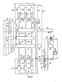
- three transverse drive beams 22,24 and 26 underlie the slats intermediate certain of the transverse frame beams 12 between which portions of the longitudinal guide beams 20 have been cut away (Fig. 2).
- Each drive beam is provided with a plurality of laterally spaced brackets 28 which extend upward through the cut away portions of the guide beams 20 for attachment to the associated slats.
- a plurality of said brackets 28 on drive beam 22 secure all of the slats 14 of the plurality of groups together; a plurality of said brackets 28 on drive beam 24 secure all of the slats 16 together; and a plurality of said brackets 28 on drive beam 26 secure all of the slats 18 together.
- Each of the transverse drive beams is connected to a source of fluid pressure power for reciprocative movement in the longitudinal direction of the conveyor.
- each of the drive beams 22, 24 and 26 is provided with downwardly extending, longitudinally spaced flanges 30 which have aligned openings therein for receiving an intermediate portion of a piston rod 32.
- Laterally spaced flanges 34 (Fig. 2) secured to the flanges 30 mount an anchor pin 36 which extends through the piston rod 32. The piston rods thus are secured to the drive beams.
- Each piston rod extends between a pair of fluid pressure cylinders 38, 38'; 40,40'; and 42,42'.
- the opposite ends of each piston rod is secured to a piston which reciprocates in its cylinder upon the application of fluid pressure, preferably hydraulic, selectively to the opposite ends of the cylinder.
- the piston head, or base ends of the cylinders opposite the piston rods are shown mounted pivotally, as by pivot pins 44, to transverse frame members 46 secured at their opposite ends to the side beams 10 of the framework.
- the rods may be secured rigidly to the frame members 46, if desired.
- the cylinder pairs are positioned on opposite sides of their respective drive beams, and hence on opposite sides of their connections to the slats. In this manner one cylinder of each pair functions to push the associated drive beam and slats while the other cylinder of the pair pulls. This arrangement provides maximum efficiency of power utilization .
- a fluid pressure system associated with the cylinders for effecting selective reciprocation of the pistons and piston rods to provide load conveying movement of the slats in the direction indicated by the arrow 48.
- This system includes a fluid pressure pump 50, preferably hydraulic, provided with outfeed conduit 52 and exhaust, or return conduit 54.
- a switching valve 56 functions to communicate said conduits interchangeably with conduits 58 and 60.
- Conduits 58 communicate with the piston rod end of cylinder 38 and with the base end of the cylinders 38', 40' and 42'.
- Conduits 60 communicate with the base ends of each of the cylinders 38, 40 and 42 and with the piston rod end of cylinder 42'.
- the piston rod end of cylinder 38 communicates with the piston rod end of cylinder 40 through conduit 62 and check valve 64.
- the piston rod end of cylinder 40 communicates with the piston rod end of cylinder 42 through conduit 66 and check valve 68.
- the check valves prevent fluid pressure flow in the direction opposite the flow direction indicated by the associated arrows until the piston rods 32 of the cylinders 38 and 40 become fully extended. Once fully extended, the associated piston engages a check valve operator 70 within the associated cylinder to switch the check valve to allow bidirectional flow.
- the piston rod ends of cylinders 38', 40' and 42' communicate freely with each other through conduits 72 and 74.
- the body of switching valve 56 is connected at one end to the piston rod 76 of a fluid pressure cylinder 78.
- the end of cylinder 78 opposite the piston rod is connected by conduit 80 and switching valve 82 to the outlet conduit 52 of the fluid pressure pump 50.
- the body of the switching valve 56 is connected at the end opposite cylinder 78 to the piston rod 84 of a fluid pressure cylinder 86.
- the end of this cylinder opposite its piston rod is connected by conduit 88 and switching valve 82 to the return conduit 54 of pump 50.
- Switching valve 82 is positioned for selective acutation by drive beams 22 and 26. As illustrated, the valve is mounted adjustably in a position below the plane of reciprocation of the drive beams. Arms 90 and 92 depend from beams 22 and 26, respectively, to engage the opposite ends of the valve 82 as the beams approach one of their limits of reciprocative movement. Thus, when beam 22 reaches its limit of movement in the load conveying direction 48, arm 90 will have engaged valve 82 and moved it to its alternate position of adjustment. Conversely, when beam 26 reaches its limit of movement in the retracting direcion (opposite direction 48), arm 92 will have engaged switch 82 and- moved it back to the position illustrated in Fig. 3.
- drive beam 26 has just previously switched valve 82 to the position illustrated _to allow pressurization of cylinder 78 from pump 50, to effect switching of valve 56 to the position illustrated.
- fluid pressure from pump 50 is directed through conduit 58 to the base ends of cylinders 38', 40' and 42' and to the piston rod end of cylinder 38 to initiate retraction of its associated piston rod and drive beam 22.
- fluid pressure from conduit 58 passes through conduit 62 and check valve 64 into the piston rod end of cylinder 40 and thence through conduit 66 and check valve 68 into the piston rod end of cylinder 42.
- valve 56 In the switched position of valve 56, fluid pressure from pump 50 is communicated through conduits 60 to the base ends of cylinders 38, 40 and 42 and to the piston rod ends cylinders 38', 40' and 42'. Conduits 58 communicate the base ends of cylinders 38', 40' and 42' and the piston rod end of cylinder 38 with the exhaust side of the pump. Since the piston rod ends of cylinders 40 and 42 are closed by check valves 64 and 68, only the piston rod 32 of cylinder 38 is caused to extend.
- the piston of cylinder 40 engages the operator 70 of check valve 68, switching the latter to allow fluid flow from the piston rod end of cylinder 42 through conduit 66 and check valve 68, thence through conduit 62 and check valve 64, through conduit 58 to the exhaust side of the pump.
- the piston rod of cylinder 42 thus is caused to extend.
- the foregoing movement of the drive beams, and hence the conveyor slats in the load conveying direction and in the opposite, retracting direction is effected by the combined power of the pairs of cylinders 38, 38'' 40,40'; and 42,42 1.
- the size of the cylinders may be reduced in comparison with the cylinder size of my earlier conveyor described in U.S. Patent No. 4,143,760 since the cylinders of this invention operate in pairs.-Thus, if the volume output of pump 50 is the same as the pump in my earlier conveyor and the effective area of each cylinder pair is the same as the corresponding single cylinder of my earlier conveyor, the speed and drive power of reciprocation of the slats will be the same.
- the application of power is more effective with the cylinder pairs of this invention, since one cylinder pulls the load while the other pushes it. Accordingly, the cylinders and piston rods may be sized in minimum dimensions.
- conduit 58 there is interposed in conduit 58 between . the switching valve 56 and the base ends of the cylinders 38', 40' and 42' an adjustable sequencing valve 94. Fluid pressure from conduit 58 is supplied to this valve by conduit 96.
- valve 94 is moved from its closed position illustrated in Fig. 4 to its alternate position opening conduit 58, when the pressure of the fluid in conduit 58 reaches a predetermined elevated magnitude, for example 2000 psi. It will be understood, however, that the valve 94 may be adjusted to open at any desired pressure.
- a conduit 98 with check valve 100 bypasses the sequencing valve 94 to provide fluid return in the direction of the arrow.
- sequencing valve 102 is interposed in conduits 60 between switching valve 56 and the piston rod end of cylinder 42'. It is supplied with fluid pressure from conduits 60 by conduit 104. Also, conduit 106 and check valve 108 bypass the valve to allow fluid return in the direction of the arrow.
- the mode is identical to Fig. 3 if the fluid pressure is sufficient to open the sequencing valves 94 and 102. This is achieved when the weight of the load on the conveyor slats provides sufficient resistance to movement of the slats as to cause the fluid pressure to rise at least to the magnitude preset to open the sequencing valve.
- the sequencing valves will close. Accordingly, the cylinders 38', 40' and 42' are blocked from the fluid pressure system and do not assist the cylinders 38, 40 and 42 in moving the load. Since the fluid pressure now is applied to only one of the two cylinders of each pair, the volume of fluid pressure from the pump being constant, the pistons in the operating cylinders are moved at twice the speed as when the fluid pressure is applied to both cylinders of each pair.
- the conveyor slats are caused to reciprocate faster or slower, automatically as the weight of the load is sensed by change in fluid pressure at the sequencing valves.
- the fluid pressure system illustrated in Fig. 5 accommodates reversal of the direction of load conveying movement of the slats.
- the fluid pressure system illustrated in Fig. 3 is modified as follows:
- the fluid pressure system illustrated in Fig. 6 affords automatic control of speed of movement of the slats, as in Fig. 4, while also accommodating reversal of direction of load conveying movement of the slats, as in Fig. 5.
- the cylinders 38', 40' and 42' are not pressurized to assist the companion cylinders. Accordingly, the load will be moved in the direction of arrow 48 at the faster rate of speed resulting from pressurization of only the one cylinder of each pair.
- switching valve 56 Upon completion of the sequencing operation, switching valve 56 will have been moved to its alternate position to cause pressurization of the base ends of the cylinders 38, 40 and 42 through conduit 60, the rod ends of these cylinders being exhausted simultaneously through conduit 116, reversing valve 110' and conduits 116 and conduit 58.
- each cylinder of a pair can have its own separate piston rod 32, with both rods connected to the same drive beam or associated slat.
- the cylinders of each pair are controlled in such manner as to cause one to extend and the other to contract simultaneously.
Landscapes
- Engineering & Computer Science (AREA)
- Mechanical Engineering (AREA)
- Reciprocating Conveyors (AREA)
Applications Claiming Priority (2)
| Application Number | Priority Date | Filing Date | Title |
|---|---|---|---|
| US06/598,164 US4691819A (en) | 1984-04-09 | 1984-04-09 | Reciprocating conveyor |
| US598164 | 1984-04-09 |
Publications (3)
| Publication Number | Publication Date |
|---|---|
| EP0158398A2 true EP0158398A2 (fr) | 1985-10-16 |
| EP0158398A3 EP0158398A3 (en) | 1986-12-30 |
| EP0158398B1 EP0158398B1 (fr) | 1990-01-24 |
Family
ID=24394497
Family Applications (1)
| Application Number | Title | Priority Date | Filing Date |
|---|---|---|---|
| EP85200494A Expired - Lifetime EP0158398B1 (fr) | 1984-04-09 | 1985-04-01 | Convoyeur à mouvement de va-et-vient |
Country Status (7)
| Country | Link |
|---|---|
| US (1) | US4691819A (fr) |
| EP (1) | EP0158398B1 (fr) |
| JP (1) | JPH06571B2 (fr) |
| AU (1) | AU571399B2 (fr) |
| CA (1) | CA1224740A (fr) |
| DE (1) | DE3575547D1 (fr) |
| MX (1) | MX161901A (fr) |
Cited By (5)
| Publication number | Priority date | Publication date | Assignee | Title |
|---|---|---|---|---|
| EP0292078A1 (fr) * | 1987-05-20 | 1988-11-23 | Hydraulic Floor Systems B.V. | Transporteur à plancher |
| US5263573A (en) * | 1990-10-25 | 1993-11-23 | Hallstrom Jr Olof A | Drive connector for reciprocating conveyor |
| EP0629567A1 (fr) * | 1992-04-15 | 1994-12-21 | Olof Alfred Hallstrom, Jr. | Système de positionnement et de transport pour une charge |
| NL9301394A (nl) * | 1993-08-11 | 1995-03-01 | Cargo Handling Systems B V | Transportvloer met aandrijving. |
| CN105474891A (zh) * | 2014-10-13 | 2016-04-13 | 吉林师范大学 | 一种玉米剥皮机的往复式玉米排序上料机构 |
Families Citing this family (26)
| Publication number | Priority date | Publication date | Assignee | Title |
|---|---|---|---|---|
| US4793468A (en) * | 1986-10-31 | 1988-12-27 | Western Waste Industries Et Al. | Multiphase sliding floor for continuous material movement |
| US4966275A (en) * | 1989-01-27 | 1990-10-30 | Hallstrom Jr Olof A | Reciprocating conveyor with detachable power drive |
| US5165525A (en) * | 1991-08-26 | 1992-11-24 | Quaeck Manfred W | Liquid-tight reciprocating floor construction |
| US5222592A (en) * | 1991-08-26 | 1993-06-29 | Quaeck Manfred W | Liquid-tight reciprocating floor construction |
| US5383548A (en) * | 1992-04-27 | 1995-01-24 | Quaeck; Manfred W. | Reciprocating floor conveyor |
| US5340264A (en) * | 1992-04-27 | 1994-08-23 | Quaeck Manfred W | Reciprocating floor conveyor |
| US5222593A (en) * | 1992-10-26 | 1993-06-29 | Quaeck Manfred W | Reciprocating floor conveyor and drive system therefor |
| US5222590A (en) * | 1992-11-19 | 1993-06-29 | Quaeck Manfred W | Reciprocating floor conveyor drive mechanism |
| US5332081A (en) * | 1992-11-19 | 1994-07-26 | Quaeck Manfred W | Reciprocating conveyor having detachable drive unit |
| US5301798A (en) * | 1993-03-08 | 1994-04-12 | Wilkens Arthur L | Reciprocating floor conveyor for caustic materials |
| US5839568A (en) * | 1994-02-07 | 1998-11-24 | Clark; Gary R. | Reciprocating floor conveyor control system |
| US5957267A (en) * | 1997-10-24 | 1999-09-28 | Quaeck; Manfred W. | Reciprocating conveyor in a trailer having higher structural and operational efficiency |
| US6003660A (en) * | 1999-03-24 | 1999-12-21 | Foster; Raymond Keith | Drive units and drive assembly for a reciprocating slat conveyors |
| DE10018142B4 (de) * | 2000-04-12 | 2011-01-20 | Polysius Ag | Kühler und Verfahren zum Kühlen von heißem Schüttgut |
| US6513648B1 (en) * | 2000-11-06 | 2003-02-04 | Olof A. Hallstrom | Reciprocating conveyor with top front drive |
| CA2459883A1 (fr) * | 2003-03-21 | 2004-09-21 | Fanotech Enviro Inc. | Bac a ordures a compartiments multiples |
| CA2451809A1 (fr) * | 2003-12-02 | 2005-06-02 | Fanotech Enviro Inc. | Transporteur a secousses muni d'un plateau de collecte de liquide |
| BRPI0604835B1 (pt) * | 2005-03-24 | 2020-01-28 | Bosch Projects Pty Ltd | aparelho e método para transportar um produto dentro de um difusor durante um processo de lixiviação contínua utilizado na indústria alimentícia, particularmente para lixiviação de cana-de-açúcar |
| US8123454B2 (en) | 2007-06-21 | 2012-02-28 | Hallco Industries, Inc. | Garbage truck and self-contained loading and unloading system therefor |
| US9452889B2 (en) | 2008-12-10 | 2016-09-27 | Hallco Industries Inc. | Bearingless reciprocating slat-type conveyor assemblies |
| US7926646B1 (en) | 2008-12-10 | 2011-04-19 | Hallco Industries, Inc. | Double-sealed, bearingless, reciprocating conveyor with slat-supporting guide trough subdecks |
| US8616365B2 (en) | 2008-12-10 | 2013-12-31 | Hallco Industries Inc. | Double-sealed, bearingless, reciprocating conveyor with slat-supporting guide trough subdecks |
| US20110056805A1 (en) * | 2009-09-04 | 2011-03-10 | Hydra-Power Systems, Inc. | Moving floor hydraulic actuator assemblies |
| WO2011035291A2 (fr) * | 2009-09-21 | 2011-03-24 | Lutz David W | Transporteur à palettes à montage par le dessous |
| JP5629084B2 (ja) * | 2009-11-17 | 2014-11-19 | 株式会社ミウラ | 搬送装置 |
| US10059527B1 (en) | 2016-02-04 | 2018-08-28 | Hallco Industries, Inc. | Raised reciprocating slat-type conveyor with floor pan |
Citations (4)
| Publication number | Priority date | Publication date | Assignee | Title |
|---|---|---|---|---|
| DE2250245B1 (de) * | 1972-10-13 | 1973-11-22 | Siemag Transhft GmbH, 5931 Netphen | Hubbalkenfoerderer |
| US4009774A (en) * | 1972-11-07 | 1977-03-01 | Lutz David E | Conveyor |
| US4143760A (en) * | 1975-01-10 | 1979-03-13 | Hallstrom Olof A | Reciprocating conveyor |
| US4144963A (en) * | 1974-08-12 | 1979-03-20 | Hallstrom Olof A | Reciprocating conveyor |
Family Cites Families (4)
| Publication number | Priority date | Publication date | Assignee | Title |
|---|---|---|---|---|
| GB1552185A (en) * | 1975-06-18 | 1979-09-12 | Gewerk Eisenhuette Westfalia | Conveyors for use in mineral mining installations |
| CA1064849A (fr) * | 1976-12-23 | 1979-10-23 | Ralph L. Andrews | Mecanisme de transfert d'articles |
| AU527790B2 (en) * | 1979-01-05 | 1983-03-24 | Olof Alfred Hallstrom Jr. | Reciprocating conveyor drive means |
| AU2811784A (en) * | 1983-03-22 | 1984-10-09 | Foster Raymond Keith | Reduced size drive/frame assembly for areciprocating floor conveyor |
-
1984
- 1984-04-09 US US06/598,164 patent/US4691819A/en not_active Expired - Lifetime
- 1984-12-11 CA CA000469840A patent/CA1224740A/fr not_active Expired
- 1984-12-20 AU AU36994/84A patent/AU571399B2/en not_active Ceased
- 1984-12-24 JP JP59271061A patent/JPH06571B2/ja not_active Expired - Lifetime
-
1985
- 1985-03-01 MX MX204494A patent/MX161901A/es unknown
- 1985-04-01 DE DE8585200494T patent/DE3575547D1/de not_active Expired - Fee Related
- 1985-04-01 EP EP85200494A patent/EP0158398B1/fr not_active Expired - Lifetime
Patent Citations (5)
| Publication number | Priority date | Publication date | Assignee | Title |
|---|---|---|---|---|
| DE2250245B1 (de) * | 1972-10-13 | 1973-11-22 | Siemag Transhft GmbH, 5931 Netphen | Hubbalkenfoerderer |
| US4009774A (en) * | 1972-11-07 | 1977-03-01 | Lutz David E | Conveyor |
| US4144963A (en) * | 1974-08-12 | 1979-03-20 | Hallstrom Olof A | Reciprocating conveyor |
| US4143760A (en) * | 1975-01-10 | 1979-03-13 | Hallstrom Olof A | Reciprocating conveyor |
| US4143760B1 (fr) * | 1975-01-10 | 1991-02-05 | A Hallstrom Olof |
Cited By (5)
| Publication number | Priority date | Publication date | Assignee | Title |
|---|---|---|---|---|
| EP0292078A1 (fr) * | 1987-05-20 | 1988-11-23 | Hydraulic Floor Systems B.V. | Transporteur à plancher |
| US5263573A (en) * | 1990-10-25 | 1993-11-23 | Hallstrom Jr Olof A | Drive connector for reciprocating conveyor |
| EP0629567A1 (fr) * | 1992-04-15 | 1994-12-21 | Olof Alfred Hallstrom, Jr. | Système de positionnement et de transport pour une charge |
| NL9301394A (nl) * | 1993-08-11 | 1995-03-01 | Cargo Handling Systems B V | Transportvloer met aandrijving. |
| CN105474891A (zh) * | 2014-10-13 | 2016-04-13 | 吉林师范大学 | 一种玉米剥皮机的往复式玉米排序上料机构 |
Also Published As
| Publication number | Publication date |
|---|---|
| EP0158398A3 (en) | 1986-12-30 |
| AU571399B2 (en) | 1988-04-14 |
| MX161901A (es) | 1991-02-28 |
| JPS60213610A (ja) | 1985-10-25 |
| EP0158398B1 (fr) | 1990-01-24 |
| US4691819A (en) | 1987-09-08 |
| DE3575547D1 (de) | 1990-03-01 |
| AU3699484A (en) | 1985-10-17 |
| CA1224740A (fr) | 1987-07-28 |
| JPH06571B2 (ja) | 1994-01-05 |
Similar Documents
| Publication | Publication Date | Title |
|---|---|---|
| US4691819A (en) | Reciprocating conveyor | |
| US4143760A (en) | Reciprocating conveyor | |
| US5222593A (en) | Reciprocating floor conveyor and drive system therefor | |
| CN1166866C (zh) | 阀组件和液压系统 | |
| US5934445A (en) | Continuously advancing reciprocating slat conveyor | |
| WO1997037914A9 (fr) | Transporteur a lattes a mouvement alternatif et a avancement continu | |
| US20150211503A1 (en) | Device for the drive control of a two-cylinder thick matter pump | |
| US5431523A (en) | Remote control for a reciprocating vehicle bed conveyor floor | |
| US5340264A (en) | Reciprocating floor conveyor | |
| US4953458A (en) | Multi-actuator hydraulic press | |
| US5228555A (en) | Load positioning and conveying system | |
| US4751818A (en) | Hydraulic drive system for platen | |
| US5310044A (en) | Reciprocating floor conveyor having slats of varied size and drive system therefor | |
| US3430540A (en) | Valve control for reciprocating piston drive with rapidly starting piston stroke | |
| EP0118497A1 (fr) | Pompe de forage et de puits a actionnement hydraulique. | |
| US4974994A (en) | Hydrostatic drive for wave generating systems in swimming pools | |
| US4917580A (en) | Pump mechanism for simultaneous delivery of two atomizer liquids to a sprayer device | |
| US4632158A (en) | Power limiting hydraulic system | |
| US4514134A (en) | Double sidewinder | |
| CA1091611A (fr) | Transporteur a lattes a mouvement alternatif | |
| US4455828A (en) | Hydraulic power unit | |
| JPS5846407B2 (ja) | 往復動コンベヤ | |
| GB2040851A (en) | Reciprocating conveyor | |
| JPS582919B2 (ja) | ジユウリヨウブツシヨウコウソウチ | |
| US2323463A (en) | Hydraulic drive |
Legal Events
| Date | Code | Title | Description |
|---|---|---|---|
| PUAI | Public reference made under article 153(3) epc to a published international application that has entered the european phase |
Free format text: ORIGINAL CODE: 0009012 |
|
| AK | Designated contracting states |
Designated state(s): DE GB NL |
|
| PUAL | Search report despatched |
Free format text: ORIGINAL CODE: 0009013 |
|
| AK | Designated contracting states |
Kind code of ref document: A3 Designated state(s): DE GB NL |
|
| 17P | Request for examination filed |
Effective date: 19870304 |
|
| 17Q | First examination report despatched |
Effective date: 19871222 |
|
| GRAA | (expected) grant |
Free format text: ORIGINAL CODE: 0009210 |
|
| AK | Designated contracting states |
Kind code of ref document: B1 Designated state(s): DE GB NL |
|
| REF | Corresponds to: |
Ref document number: 3575547 Country of ref document: DE Date of ref document: 19900301 |
|
| PLBE | No opposition filed within time limit |
Free format text: ORIGINAL CODE: 0009261 |
|
| STAA | Information on the status of an ep patent application or granted ep patent |
Free format text: STATUS: NO OPPOSITION FILED WITHIN TIME LIMIT |
|
| 26N | No opposition filed | ||
| PGFP | Annual fee paid to national office [announced via postgrant information from national office to epo] |
Ref country code: GB Payment date: 19940311 Year of fee payment: 10 |
|
| PG25 | Lapsed in a contracting state [announced via postgrant information from national office to epo] |
Ref country code: GB Effective date: 19950401 |
|
| PGFP | Annual fee paid to national office [announced via postgrant information from national office to epo] |
Ref country code: NL Payment date: 19950430 Year of fee payment: 11 |
|
| NLS | Nl: assignments of ep-patents |
Owner name: VSR TECHNOLOGIE GMBH TE MUELHEIM A.D. RUHR, BONDSR |
|
| GBPC | Gb: european patent ceased through non-payment of renewal fee |
Effective date: 19950401 |
|
| PG25 | Lapsed in a contracting state [announced via postgrant information from national office to epo] |
Ref country code: NL Effective date: 19961101 |
|
| NLV4 | Nl: lapsed or anulled due to non-payment of the annual fee |
Effective date: 19961101 |
|
| PGFP | Annual fee paid to national office [announced via postgrant information from national office to epo] |
Ref country code: DE Payment date: 20030523 Year of fee payment: 19 |
|
| PG25 | Lapsed in a contracting state [announced via postgrant information from national office to epo] |
Ref country code: DE Free format text: LAPSE BECAUSE OF NON-PAYMENT OF DUE FEES Effective date: 20041103 |