EP0157005A2 - Führungsvorrichtung für eine Handwerkzeugmaschine - Google Patents
Führungsvorrichtung für eine Handwerkzeugmaschine Download PDFInfo
- Publication number
- EP0157005A2 EP0157005A2 EP84116268A EP84116268A EP0157005A2 EP 0157005 A2 EP0157005 A2 EP 0157005A2 EP 84116268 A EP84116268 A EP 84116268A EP 84116268 A EP84116268 A EP 84116268A EP 0157005 A2 EP0157005 A2 EP 0157005A2
- Authority
- EP
- European Patent Office
- Prior art keywords
- clamping
- guide rail
- guide
- guide device
- piece
- Prior art date
- Legal status (The legal status is an assumption and is not a legal conclusion. Google has not performed a legal analysis and makes no representation as to the accuracy of the status listed.)
- Ceased
Links
Images
Classifications
-
- B—PERFORMING OPERATIONS; TRANSPORTING
- B23—MACHINE TOOLS; METAL-WORKING NOT OTHERWISE PROVIDED FOR
- B23Q—DETAILS, COMPONENTS, OR ACCESSORIES FOR MACHINE TOOLS, e.g. ARRANGEMENTS FOR COPYING OR CONTROLLING; MACHINE TOOLS IN GENERAL CHARACTERISED BY THE CONSTRUCTION OF PARTICULAR DETAILS OR COMPONENTS; COMBINATIONS OR ASSOCIATIONS OF METAL-WORKING MACHINES, NOT DIRECTED TO A PARTICULAR RESULT
- B23Q9/00—Arrangements for supporting or guiding portable metal-working machines or apparatus
- B23Q9/0014—Portable machines provided with or cooperating with guide means supported directly by the workpiece during action
- B23Q9/0028—Portable machines provided with or cooperating with guide means supported directly by the workpiece during action the guide means being fixed only on the machine
-
- Y—GENERAL TAGGING OF NEW TECHNOLOGICAL DEVELOPMENTS; GENERAL TAGGING OF CROSS-SECTIONAL TECHNOLOGIES SPANNING OVER SEVERAL SECTIONS OF THE IPC; TECHNICAL SUBJECTS COVERED BY FORMER USPC CROSS-REFERENCE ART COLLECTIONS [XRACs] AND DIGESTS
- Y10—TECHNICAL SUBJECTS COVERED BY FORMER USPC
- Y10T—TECHNICAL SUBJECTS COVERED BY FORMER US CLASSIFICATION
- Y10T83/00—Cutting
- Y10T83/667—Tool carrier or guide affixed to work during cutting
- Y10T83/68—Entirely work supported
Definitions
- the invention relates to a guide device for a hand tool according to the preamble of the main claim.
- Guide devices for parallel cuts and circular cuts have already become known in which the base plate of the hand power tool has a holder and a clamping device for a guide rail.
- the base plate must usually be kept relatively narrow when working with the hand-held hand-held power tool, so as not to be a hindrance when cutting close to the edge.
- it carries devices for pivoting the base plate relative to the machine body and holding the foot plate in the selected setting position. Especially with jigsaws but also with circular saws, the space at the top of the footplate, between the footplate and the machine body and near the guide rail, is relatively narrow.
- the guide device according to the invention with the characterizing features of the main claim has the advantage that the clamping device itself assigned to the guide rail counting as an accessory and the handle can be arranged outside the narrow space between the footplate and the machine body.
- the clamping projection for gripping over part of the footplate, the clamping screw or the like.
- Clamping means and its handle move laterally away from the footplate. It is freely accessible and can also be operated with protective gloves.
- the footplate only needs to have guide openings in its side walls into which the guide rail can be inserted.
- the clamping device can be supplied with the guide rail as an accessory.
- a one-piece clip made of spring steel with two tabs around the guide rail, which has a thread for a clamping screw in its central part and a third tab that runs in the direction of the guide rail, the clamping projection ha: and is resiliently biased against the clamping screw.
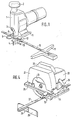
- FIG. 1 shows a perspective view of a jigsaw with a guide device according to the invention
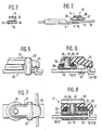
- FIG. 2 shows a detail of the guide device partially in a side view
- FIG. 3 shows a view of FIG. 2 in the direction X
- FIG. 1 shows a perspective view of a jigsaw with a guide device according to the invention
- FIG. 2 shows a detail of the guide device partially in a side view
- FIG. 3 shows a view of FIG. 2 in the direction X
- FIG. 1 shows a perspective view of a jigsaw with a guide device according to the invention
- FIG. 2 shows a detail of the guide device partially in a side view
- FIG. 3 shows a view of FIG. 2 in the direction X
- FIG. 1 shows a perspective view of a jigsaw with a guide device according to the invention
- FIG. 2 shows a detail of the guide device partially in a side view
- FIG. 3 shows a view of FIG. 2 in the direction X
- FIG. 4 shows another perspective view of a circular saw with the Guide device according to the invention, with a clamping device according to Figures 1 to 3, Figure 5 as a further example of a clamping device such with an injection molded, pressed or cast clamp and with a special arrangement of the clamping screw in the side view, Figure 6 shows a section to Figure 5, Figure 7 a plan view of Figure 5 and Figure 8 shows a section through a further possible embodiment for a clamping device for the guide device according to the invention.
- FIGS. 1 to 3 shows a hand-held power tool designed as a jigsaw with a machine body 1, an additional handle 2, a lifting rod 3, a jigsaw blade 4 clamped in this and a foot plate 5 pivotally connected to the machine body.
- the foot plate 5 has raised edges 6 and 7 are incorporated into the rectangular recesses 8 and 9.
- a guide rail 10 is pushed through these recesses 8 and 9.
- the free end of the guide rail 10 carries a parallel stop 11.
- a clamping device 12 is also pushed onto the guide rail 10.
- This clamping device 12 consists in detail of a clip 13 and a clamping screw 14.
- the clip 13 has two tabs 15 and 16 from its central part from the guide rail 10 down.
- a third tab 18 of the clip 13 extends in the longitudinal direction of the guide rail and is bent over from the threaded tube 17 from the side of the clip 13 facing away from the base plate 5. towards the base plate 5. Over the threaded tube 17, this tab 18 has a through hole for the screw bolt of the clamping screw 14. The free end of the tab 18 forms a hook-shaped clamping projection 19 which can overlap one of the edges 6, 7 of the base plate 5.
- the bracket 13 is made of spring steel. The tab 18 rests under spring tension on the head of the clamping screw 14.
- the clamping screw 14 is loosened so far that the clamping projection 19 probably holds the edge of the foot plate 5 assigned to it, but the guide rail 10 is not yet clamped.
- the clamping screw 14 is tightened further, so that the end face of the threaded bolt of this clamping screw 14 facing away from the handle of the clamping screw 14 presses on the guide rail. So the base plate 5 and the guide rail are clamped together by means of the clamping device 12.
- the clamping screw 14 must be loosened to such an extent that the clamping projection 19 of the clamp 13 can also be lifted over the edge of the base plate 5 assigned to it. Then you can pull the guide rail 10 out of the recesses 8 and 9.
- the guide device thus removed, with the guide rail and the parallel stop 11, carries the clamping device 12, which can be securely clamped on the guide rail 10 by means of the clamping screw 14.
- the exemplary embodiment according to FIG. 4 shows a hand-held circular saw as a hand-held power tool with a machine housing 20, a protective hood 21, a handle 22 and a circular saw blade 23.
- a foot plate 24 is connected to the protective hood 21 and also has raised edges 25.
- Tilting device 26 allows the footplate 24 to be adjusted within an angular range of 45 °.
- a guide rail 27 is used instead of the guide rail 10, to which a holder 28 for a parallel stop 29 is molded.
- the same clamping device 12 is used as the clamping device as in the first exemplary embodiment according to FIGS. 1 to 3.
- the advantageous arrangement of the clamping device 12 next to the base plate 24 becomes particularly clear.
- the inclination device 26 has enough space on the surface of the footplate 24.
- FIGS. 5 to 7 show another embodiment of a clamping device, which is designated by 30 and can also be made of plastic.
- a clamping piece 31 is provided with a bracket 32 through which a guide rail 10 or 27 can be passed.
- a clamping projection 33 has a groove 34 which fits onto the edges 6, 7, 25.
- the central part of the clamping piece 31 has a threaded bore 35. This is surrounded by a cylindrical projection 36.
- a clamping screw 37 is screwed into the threaded bore 35 from the rail side.
- the knurled head 38 has on its end face facing the clamping piece 31 a recess 39 into which the projection 36 fits.
- a springy and / or soft-elastic disk 40 is inserted into this recess 39. It serves as a rotation lock for the clamping screw 37.
- FIG 8 shows a further embodiment of a clamping device, which is designated by 41.
- a clamping bracket 42 has a tunnel 43 for receiving a guide rail 10 or 27. Furthermore, it has a cylindrical projection 44 to which a threaded bore 45 is arranged centrally.
- a clamping piece 46 is arranged above this clamping bracket 42 and has a hook-shaped clamping projection 47.
- a clamping screw 49 is screwed into the threaded bore 45 through a through hole 48 in the clamping piece 46.
- the head 50 is also gripped by a knurl.
- a tip 51 of the clamping screw 49 can clamp the clamping bracket 42 on the guide rail 10/27.
- the head 50 of the clamping screw 49 presses the clamping piece 46 with its clamping projection 47 onto an edge 6/7/25 of a foot plate 5/24.
- a resilient and / or elastic component 52 is inserted between the clamping bracket 42 and the clamping piece 46 around the projection 44.
- a support tab 53 of the clamping piece 46 defines on its side the minimum distance between the clamping bracket 42 and the clamping piece 46.
Landscapes
- Engineering & Computer Science (AREA)
- Mechanical Engineering (AREA)
- Sawing (AREA)
Abstract
Description
- Die Erfindung geht aus von einer Führungsvorrichtung für eine Handwerkzeugmaschine nach der Gattung des Hauptanspruchs. Es sind schon solche Führungsvorrichtungen für Parallelschnitte und Kreisschnitte bekanntgeworden, bei denen die Fußplatte der Handwerkzeugmaschine eine Halterung und eine, Klemmvorrichtung für eine Führungsschiene besitzt. Die Fußplatte muß für die Arbeit mit der handgeführten Handwerkzeugmaschine meist relativ schmal gehalten werden, um bei randnahen Schnitten nicht hinderlich zu sein. Zudem trägt sie Vorrichtungen zum Schwenken der Grundplatte gegenüber dem Maschinenkörper und Festhalten der Fußplatte in der gewählten Einstellage. Besonders bei Stichsägen aber auch bei Handkreissägen ist deshalb der Raum an der Oberseite der Fußplatte, zwischen der Fußplatte und dem Maschinenkörper und in der Nähe der Führungsschiene, relativ eng. Das Festklemmen und Lösen der Führungsschiene ist daher verhältnismäßig schwierig und umständlich. Außerdem macht es diese Anordnung erforderlich, jede Handwerkzeugmaschine in der Grundaustattung schon mit der Klemmvorrichtung auszustatten, obwohl diese vom Benutzer vielleicht nicht benötigt wird. Schließlich gehen bewegliche Teile der Klemmvorrichtung leicht verloren.
- Die erfindungsgemäße Führungsvorrichtung mit den kennzeichnenden Merkmalen des Hauptanspruchs hat demgegenüber den Vorteil, daß die Klemmvorrichtung der als Zubehör zählenden Führungsschiene selbst zugeordnet und deren Handhabe außerhalb des engen Raumes zwischen der Fußplatte und dem Maschinenkörper angeordnet werden kann. Durch den Klemmvorsprung zum Übergreifen eines Teils der Fußplatte rückt die Klemmschraube oder dgl. Klemmittel und deren Handhabe seitlich weg von der Fußplatte. Sie ist so frei zugänglich und kann auch mit Schutzhandschuhen betätigt werden. Die Fußplatte braucht nur noch Führungsöffnungen in ihren Seitenwänden zu haben, in die die Führungsschiene eingeschoben werden kann. Die Klemmvorrichtung kann mit der Führungsschiene als Zubehör geliefert werden.
- urch die in den Unteransprüchen aufgeführten Maßnahmen sind vorteilhafte Weiterbildungen und Verbesserungen der im Hauptanspruch angegebenen Führungsvorrichtung möglich. Besonders vorteilhaft ist eine einstückig aus Federbandstahl gefertige Klammer mit zwei die Führungsschiene umgreifenden Lappen, die in ihrem Mittelteil ein Gewinde für eine Klemmschraube aufnimmt und einen dritten Lappen hat, der in Richtung der Führungsschiene verläuft, den Klemmvorsprung ha: und federnd gegen die Klemmschraube vorgespannt ist.
- Mehrere Ausführungsbeispiele des Erfindungsgegenstandes sind in der Zeichnung dargestellt und in der nachfolgenden Beschreibung näher erläutert. Es zeigen Figur 1 eine perspektivische Darstellung einer Stichsäge mit einer erfindungsgemäßen Führungsvorrichtung, Figur 2 eine Einzelheit der Führungsvorrichtung in der Seitenansicht teilweise geschnitten, Figur 3 eine Ansicht zu Figur 2 in Richtung X, Figur 4 in einem anderen Ausführungsbeispiel eine perspektivische Darstellung einer Handkreissäge mit der erfindungsgemäßen Führungsvorrichtung, mit einer Klemmvorrichtung nach den Figuren 1 bis 3, Figur 5 als weiteres Beispiel einer Klemmvorrichtung eine solche mit einer gespritzten, gepreßten oder gegossenen Klammer und mit besonderer Anordnung der Klemmschraube in der Seitenansicht, Figur 6 einen Schnitt zu Figur 5, Figur 7 eine Draufsicht zu Figur 5 und Figur 8 einen Schnitt durch eine weitere mögliche Ausführungsform für eine Klemmvorrichtung zur erfindungsgemäßen Führungsvorrichtung.
- Das Ausführungsbeispiel nach den Figuren 1 bis 3 zeigt eine als Stichsäge ausgebildete Handwerkzeugmaschine mit einem Maschinenkörper 1, einer Zusatzhandhabe 2, einer Hubstange 3, einem in diese eingespannten Stichsägeblatt 4 und einer schwenkbar mit dem Maschinenkörper verbundenen Fußplatte 5. Die Fußplatte 5 besitzt hochgezogene Ränder 6 und 7 in die rechteckige Ausnehmungen 8 und 9 eingearbeitet sind. Durch diese Ausnehmungen 8 und 9 ist eine Führungsschiene 10 hindurchgeschoben. Das freie Ende der Führungsschiene 10 trägt einen Parallelanschlag 11. Ebenfalls auf die Führungsschiene 10 aufgeschoben ist eine Klemmvorrichtung 12. Diese Klemmvorrichtung 12 besteht im einzelnen aus einer Klammer 13 und einer Klemmschraube 14. Die Klammer 13 hat zwei Lappen 15 und 16 die von ihrem Mittelteil aus die Führungsschiene 10 nach unten umfassen. Im Mittelteil der Klammer 13 befindet sich ein Gewindetubus 17, in den die Klemmschraube 14 eingeschraubt werden kann. Ein dritter Lappen 18 der Klammer 13 verläuft in Längsrichtung der Führungsschiene und ist von der der Fußplatte 5 abgewendeten Seite der Klammer 13 über den Gewindetubus 17 hinweg abgebogen,. hin zur Fußplatte 5. Über dem Gewindetubus 17 besitzt dieser Lappen 18 eine Durchgangsbohrung für den Schraubenbolzen der Klemmschraube 14. Das freie Ende des Lappens 18 bildet einen hakenförmigen Klemmvorsprung 19, der einen der Ränder 6, 7 der Fußplatte 5 übergreifen kann. Die Klammer 13 ist aus Federbandstahl angefertigt. Der Lappen 18 liegt unter Federspannung am Kopf der Klemmschraube 14 an.
- Zum Einstellen des Abstandes zwischen dem Stichsägeblatt 4 und dem Parallelanschlag 11 ist die Klemmschraube 14 so weit gelöst, daß der Klemmvorsprung 19 wohl den ihm zugeordneten Rand der Fußplatte 5 hält, die Führungsschiene 10 aber noch nicht festgeklemmt ist. Nach dem Einstellen des gewünschten Abstandes wird die Klemmschraube 14 weiter angezogen, so daß die von der Handhabe der Klemmschraube 14 abgewendete Stirnseite des Gewindebolzens dieser Klemmschraube 14 auf die Führungsschiene drückt. So werden die Fußplatte 5 und die Führungsschiene mittels der Klemmvorrichtung 12 miteinander verklemmt. Zum Abnehmen der Führungsschiene 10 muß die Klemmschraube 14 so weit gelöst werden, daß auch der Klemmvorsprung 19 der Klammer 13 über den ihm zugeordneten Rand der Fußplatte 5 gehoben werden kann. Dann kann man die Führungsschiene 10 aus den Ausnehmungen 8 und 9 herausziehen. Die so entfernte Führungsvorrichtung mit der Führungsschiene und dem Parallelanschlag 11 trägt die Klemmvorrichtung 12, die man mittels der Klemmschraube 14 unverlierbar auf der Führungsschiene 10 festklemmen kann.
- Das Ausführungsbeispiel nach Figur 4 zeigt eine Handkreissäge als Handwerkzeugmaschine mit einem Maschinengehäuse 20, einer Schutzhaube 21, einem Handgriff 22 und einem Kreissägeblatt 23. Mit der Schutzhaube 21 ist eine Fußplatte 24 verbunden, die ebenfalls hochgezogene Ränder 25 hat. Eine
- Neigungsvorrichtung 26 gestattet das Verstellen der Fußplatte 24 in einem Winkelbereich von 45°. In diesem Ausführungsbeispiel ist eine Führungsschiene 27 anstelle der Führungsschiene 10 verwendet, an die ein Halter 28 für einen Parallelanschlag 29 angeformt ist. Als Klemmvorrichtung ist die- gleiche Klemmvorrichtung 12 verwendet wie im ersten Ausführungsbeispiel nach den Figuren 1 bis 3. Hier wird das vorteilhafte der Anordnung der Klemmvorrichtung 12 neben der Fußplatte 24 besonders deutlich. Mit dieser Lösung hat die Neigungsvorrichtung 26 genügend Platz auf der Oberfläche der Fußplatte 24. Die Figuren 5 bis 7 zeigen eine andere Ausführung einer Klemmvorrichtung, die mit 30 bezeichnet ist und auch in Kunststoff ausgeführt werden kann. Ein Klemmstück 31 ist mit einem Bügel 32 versehen, durch den eine Führungs-Schiene 10 bzw. 27 hindurchgeführt werden kann. Ein Klemmvorsprung 33 besitzt eine auf die Ränder 6, 7, 25 passende Nut 34. Der Mittelteil des Klemmstücks 31 hat eine Gewindebohrung 35. Diese ist umgeben mit einem zylindrischen Vorsprung 36. In die Gewindebohrung 35 ist von der Schienenseite her eine Klemmschraube 37 eingeschraubt. Deren Rändelkopf 38 besitzt an seiner dem Klemmstück 31 zugewendeten Stirnfläche eine Ausdrehung 39, in die der Vorsprung 36 paßt. In diese Ausdrehung 39 ist eine federnde und/oder weichelastische Scheibe 40 eingelegt. Sie dient als Drehsicherung für die Klemmschraube 37.
- Mit dieser Klemmvorrichtung 30 ist eine komplette, aus Kunststoff herstellbare Lösung gefunden, die keine sperrig vorstehenden Teile hat. Zum Festklemmen der Führungsschienen 10 bzw. 27 stützt sich der Rändelkopf 38 der Klemmschraube 37 an der Schienenoberfläche ab. Die über die Schienen und Klemmstückbreite hinaus ragenden Teile des Rändelkopfes 38 bieten genügend griffige Handhaben.
- Figur 8 zeigt ein weiteres Ausführungsbeispiel für eine Klemmvorrichtung, das mit 41 bezeichnet ist. Ein Klemmbügel 42 besitzt einen Tunnel 43 zur Aufnahme einer Führungsschiene 10 oder 27. Weiter hat er einen zylindrischen Vorsprung 44 zu dem zentrisch eine Gewindebohrung 45 angeordnet ist. Über diesem Klemmbügel 42 ist ein Klemmstück 46 angeordnet, das einen hakenförmigen Klemmvorsprung 47 hat. Durch ein Durchgangsloch 48 in dem Klemmstück 46 ist eine Klemmschraube 49 in die Gewindebohrung 45 eingeschraubt. Deren Kopf 50 ist ebenfalls durch ein Rändel griffig gemacht. Eine Kuppe 51 der Klemmschraube 49 kann den Klemmbügel 42 auf der Führungs- schiene 10/27 festklemmen. Zugleich drückt dann der Kopf 50 der Klemmschraube 49 das Klemmstück 46 mit seinem Klemmvorsprung 47 auf einen Rand 6/7/25 einer Fußplatte 5/24. Ein federndes und/oder elastiches Bauelement 52 ist zwischen den Klemmbügel 42 und das Klemmstück 46 um den Vorsprung 44 herum eingelegt. Eine Stütznase 53 des Klemmstücks 46 legt auf ihrer Seite den Mindestabstand zwischen dem Klemmbügel 42 und dem Klemmstück 46 fest.
Claims (12)
Applications Claiming Priority (2)
| Application Number | Priority Date | Filing Date | Title |
|---|---|---|---|
| DE8410794U | 1984-04-06 | ||
| DE8410794U DE8410794U1 (de) | 1984-04-06 | 1984-04-06 | Führungsvorrichtung für eine Handwerkzeugmaschine |
Publications (2)
| Publication Number | Publication Date |
|---|---|
| EP0157005A2 true EP0157005A2 (de) | 1985-10-09 |
| EP0157005A3 EP0157005A3 (de) | 1987-02-04 |
Family
ID=6765637
Family Applications (1)
| Application Number | Title | Priority Date | Filing Date |
|---|---|---|---|
| EP84116268A Ceased EP0157005A3 (de) | 1984-04-06 | 1984-12-22 | Führungsvorrichtung für eine Handwerkzeugmaschine |
Country Status (3)
| Country | Link |
|---|---|
| US (1) | US4628608A (de) |
| EP (1) | EP0157005A3 (de) |
| DE (1) | DE8410794U1 (de) |
Cited By (2)
| Publication number | Priority date | Publication date | Assignee | Title |
|---|---|---|---|---|
| FR2726218A1 (fr) * | 1994-10-27 | 1996-05-03 | Ryobi Ltd | Rabot ayant un mecanisme de fixation d'une regle de guidage et procede de fixation d'une regle de guidage d'un rabot |
| WO1999065647A1 (en) * | 1998-06-17 | 1999-12-23 | Clete Darnell | Combination saw guide and gauge |
Families Citing this family (32)
| Publication number | Priority date | Publication date | Assignee | Title |
|---|---|---|---|---|
| US4922616A (en) * | 1988-11-07 | 1990-05-08 | Oskar Bensel | Industrial saw guide attachment |
| US5035061A (en) * | 1990-01-02 | 1991-07-30 | Timothy Bradbury | Guide for hand-held power tools |
| US10361802B1 (en) | 1999-02-01 | 2019-07-23 | Blanding Hovenweep, Llc | Adaptive pattern recognition based control system and method |
| US8352400B2 (en) | 1991-12-23 | 2013-01-08 | Hoffberg Steven M | Adaptive pattern recognition based controller apparatus and method and human-factored interface therefore |
| USD376527S (en) | 1995-07-27 | 1996-12-17 | Wolfcraft, Inc. | Rip fence and cutting guide |
| US5815931A (en) * | 1996-10-29 | 1998-10-06 | Robert E. Cummings | Cutting guide for controlling the direction and cut of a hand held power cutting tool |
| DE19650877A1 (de) * | 1996-12-07 | 1998-06-10 | Bosch Gmbh Robert | Handwerkzeugmaschine mit Parallelanschlag |
| US5901450A (en) * | 1997-11-21 | 1999-05-11 | Milwaukee Electric Tool Corporation | Rip guide for a circular saw |
| US7966078B2 (en) | 1999-02-01 | 2011-06-21 | Steven Hoffberg | Network media appliance system and method |
| US6591509B2 (en) | 2001-04-13 | 2003-07-15 | Leblanc Rodrigue Raymond | Floating bench saw guide |
| US6484410B1 (en) * | 2001-10-04 | 2002-11-26 | Kenneth Ralph Meastas | Guide for power tools |
| US6757984B2 (en) | 2002-06-11 | 2004-07-06 | David N. Harris | Saw guide for use with lined sheet material |
| US6757981B2 (en) * | 2002-07-19 | 2004-07-06 | Philip W. Hampton | Universal rip guide for circular saw |
| US7610839B1 (en) | 2002-11-25 | 2009-11-03 | Bessette Bernard J | Guide for the precise control of portable power tools |
| US20040172845A1 (en) * | 2003-03-05 | 2004-09-09 | Eichhorn Joseph R. | Rip guide tool |
| US7526867B2 (en) * | 2003-09-19 | 2009-05-05 | Gmca Pty Limited | Tool with clamping apparatus and an improved scrolling mechanism |
| US7246446B2 (en) * | 2004-04-15 | 2007-07-24 | Nomis, Llc | Adjustable guide rail for hand tools |
| US7958641B1 (en) * | 2007-05-09 | 2011-06-14 | Woodman Tools, Llc | Rolling plate assembly attachment for portable power cutting tools including an improved structural design and manufactured out of improved materials, an improved wheel configuration, and an adjustable bevel gear and a cutting guide |
| EP2018936B1 (de) * | 2007-07-26 | 2010-07-14 | BLACK & DECKER INC. | Fußplatte |
| US8230607B2 (en) * | 2008-05-09 | 2012-07-31 | Milwaukee Electric Tool Corporation | Keyless blade clamp for a power tool |
| DE102010038675A1 (de) * | 2010-07-30 | 2012-02-02 | Hilti Aktiengesellschaft | Befestigungsvorrichtung |
| DE102012105520A1 (de) * | 2012-06-25 | 2014-04-24 | C. & E. Fein Gmbh | Tiefenanschlag für oszillierendes Werkzeug |
| US20160221091A1 (en) * | 2015-02-03 | 2016-08-04 | General Electric Company | Turbomachine blade ring segment cutting tool and related guide |
| US10486251B2 (en) * | 2016-05-16 | 2019-11-26 | Makita Corporation | Machining devices |
| USD1005076S1 (en) | 2019-05-21 | 2023-11-21 | Nomis Llc | Saw guide |
| EP3998132A4 (de) * | 2019-07-12 | 2022-10-05 | Koki Holdings Co., Ltd. | Elektrowerkzeug |
| JP7455661B2 (ja) * | 2020-05-22 | 2024-03-26 | 株式会社マキタ | 携帯用加工機 |
| WO2022109381A1 (en) | 2020-11-23 | 2022-05-27 | Milwaukee Electric Tool Corporation | Track saw assembly |
| USD1119500S1 (en) | 2021-03-09 | 2026-03-24 | Bam Ip Holding Llc | Track saw guide |
| US11883891B2 (en) | 2021-03-09 | 2024-01-30 | Nomis Llc | Track saw |
| US12465982B2 (en) | 2022-02-24 | 2025-11-11 | Techtronic Cordless Gp | Track saw including plunge lockout mechanism |
| US12083613B2 (en) | 2022-10-18 | 2024-09-10 | Techtronic Cordless Gp | Track saw including plunge lockout mechanism |
Family Cites Families (15)
| Publication number | Priority date | Publication date | Assignee | Title |
|---|---|---|---|---|
| US2676624A (en) * | 1951-07-28 | 1954-04-27 | Arthur C Gecmen | Guide carriage for power-driven hand tools |
| GB785906A (en) * | 1956-01-30 | 1957-11-06 | Salter & Co Ltd G | Improvements relating to clip fastening devices for securing panels to supports |
| US2917267A (en) * | 1956-12-07 | 1959-12-15 | Librascope Inc | Clamp |
| GB939379A (en) * | 1962-03-08 | 1963-10-16 | Parramore & Sons 1924 Ltd F | Improvements in or relating to wood-working planes |
| GB1074972A (en) * | 1963-03-01 | 1967-07-05 | Vincent Alfred Statham | Improved clamp |
| US4077292A (en) * | 1976-03-26 | 1978-03-07 | Cole Eugene E | Guiding assembly for a portable power tool |
| US4016649A (en) * | 1976-06-11 | 1977-04-12 | Kloster Pattern Company | Circular saw guide |
| US4065114A (en) * | 1976-12-03 | 1977-12-27 | Pennington Charles A | Guide for a motorized circular handsaw |
| US4125942A (en) * | 1977-02-09 | 1978-11-21 | Horner Ralph J | Guide for hand tools |
| FR2406113A1 (fr) * | 1977-10-13 | 1979-05-11 | Usiprofil Sarl | Dispositif de fixation |
| US4138914A (en) * | 1977-12-12 | 1979-02-13 | Reeder Donald G | Saw guide apparatus |
| DE2919611C2 (de) * | 1979-05-16 | 1985-11-14 | Licentia Patent-Verwaltungs-Gmbh, 6000 Frankfurt | Handkreissäge mit einer Tragschiene für einen Parallelanschlag |
| US4335512A (en) * | 1980-07-17 | 1982-06-22 | Portalign Toll Corporation | Attachment for a power hand saw |
| DE8024714U1 (de) * | 1980-09-16 | 1982-02-04 | Robert Bosch Gmbh, 7000 Stuttgart | Führungsvorrichtung für eine Handwerkzeugmaschine |
| US4397089A (en) * | 1981-01-26 | 1983-08-09 | Andrew Mason Pease | Straight line guide on electric power hand saw |
-
1984
- 1984-04-06 DE DE8410794U patent/DE8410794U1/de not_active Expired
- 1984-12-21 US US06/684,910 patent/US4628608A/en not_active Expired - Lifetime
- 1984-12-22 EP EP84116268A patent/EP0157005A3/de not_active Ceased
Cited By (3)
| Publication number | Priority date | Publication date | Assignee | Title |
|---|---|---|---|---|
| FR2726218A1 (fr) * | 1994-10-27 | 1996-05-03 | Ryobi Ltd | Rabot ayant un mecanisme de fixation d'une regle de guidage et procede de fixation d'une regle de guidage d'un rabot |
| WO1999065647A1 (en) * | 1998-06-17 | 1999-12-23 | Clete Darnell | Combination saw guide and gauge |
| US6216355B1 (en) | 1998-06-17 | 2001-04-17 | Clete Darnell | Combination saw guide and gauge |
Also Published As
| Publication number | Publication date |
|---|---|
| US4628608A (en) | 1986-12-16 |
| DE8410794U1 (de) | 1985-10-03 |
| EP0157005A3 (de) | 1987-02-04 |
Similar Documents
| Publication | Publication Date | Title |
|---|---|---|
| EP0157005A2 (de) | Führungsvorrichtung für eine Handwerkzeugmaschine | |
| DE3239986A1 (de) | Handwerkzeugmaschine mit einem kreisscheibenfoermigen werkzeug | |
| DE8404981U1 (de) | Bogengreifer fuer druckmaschinen | |
| DE3006299A1 (de) | Stichsaege | |
| DE4024031A1 (de) | Hand-schraubgeraet | |
| DE19756766A1 (de) | Elektrische Handwerkzeugmaschine | |
| EP2183072A1 (de) | Handwerkzeugmaschine | |
| EP0324444A2 (de) | Ritzvorrichtung | |
| CH650958A5 (en) | Jig saw with bearing plate which can be fastened to the saw housing | |
| EP0479818B1 (de) | Parallel- und winkelanschlag | |
| CH673975A5 (de) | ||
| DE8910373U1 (de) | Haltevorrichtung für das klingenförmige Schneidmesser eines Mikrotoms | |
| EP1466690A1 (de) | Säbelsäge mit Justiervorrichtung für eine Führungsvorrichtung | |
| DE19700151A1 (de) | Verbesserung bei Vorrichtungen zum Entfernen von Windschutzscheiben | |
| DE3428445C3 (de) | Verwendung eines zur Befestigung eines Sägeblattes an einer Hubstange einer Stichsäge vorgesehenen Druckstückes | |
| EP1066905B1 (de) | Stichsäge mit Sägeblattführungvorrichtung | |
| DE3443140C2 (de) | ||
| DE20316190U1 (de) | Vorrichtung zum lösbaren Befestigen elektrisch betriebener Werkzeugmaschinen | |
| EP0799677A2 (de) | Vorrichtung zur Aufnahme eines motorgetriebenen Werkzeuges, insbesondere eines Handkreissäge | |
| DE9006197U1 (de) | Befestigungsvorrichtung für ein Laubsägeblatt | |
| EP1059151B1 (de) | Handgeführte Laubsägemaschine mit Auflagefläche und Werkstückniederhalter | |
| EP4617022A1 (de) | Montageelement für eine führungsschiene sowie führungsanordnung zum führen einer handkreissäge | |
| DE3702926A1 (de) | Stichsaege mit einer fussplatte | |
| EP1110651A2 (de) | Handkreissäge | |
| DE102023134936A1 (de) | Schnittlängen-Begrenzungsvorrichtung für tragbare Werkzeugmaschinen |
Legal Events
| Date | Code | Title | Description |
|---|---|---|---|
| PUAI | Public reference made under article 153(3) epc to a published international application that has entered the european phase |
Free format text: ORIGINAL CODE: 0009012 |
|
| 17P | Request for examination filed |
Effective date: 19841222 |
|
| AK | Designated contracting states |
Designated state(s): DE GB NL |
|
| PUAL | Search report despatched |
Free format text: ORIGINAL CODE: 0009013 |
|
| AK | Designated contracting states |
Kind code of ref document: A3 Designated state(s): DE GB NL |
|
| 17Q | First examination report despatched |
Effective date: 19880802 |
|
| STAA | Information on the status of an ep patent application or granted ep patent |
Free format text: STATUS: THE APPLICATION HAS BEEN REFUSED |
|
| 18R | Application refused |
Effective date: 19881217 |
|
| RIN1 | Information on inventor provided before grant (corrected) |
Inventor name: KUHLMANN, GERHARD Inventor name: WOLF, ERWIN, DIPL.-ING. |