EP0156717B1 - Dispositif d'affichage des séquences ou de la température d'un appareil de cuisson - Google Patents
Dispositif d'affichage des séquences ou de la température d'un appareil de cuisson Download PDFInfo
- Publication number
- EP0156717B1 EP0156717B1 EP19850400457 EP85400457A EP0156717B1 EP 0156717 B1 EP0156717 B1 EP 0156717B1 EP 19850400457 EP19850400457 EP 19850400457 EP 85400457 A EP85400457 A EP 85400457A EP 0156717 B1 EP0156717 B1 EP 0156717B1
- Authority
- EP
- European Patent Office
- Prior art keywords
- temperature
- sectors
- sequence
- display device
- display unit
- Prior art date
- Legal status (The legal status is an assumption and is not a legal conclusion. Google has not performed a legal analysis and makes no representation as to the accuracy of the status listed.)
- Expired
Links
- 238000010411 cooking Methods 0.000 title claims description 11
- 230000001105 regulatory effect Effects 0.000 description 1
Images


Classifications
-
- F—MECHANICAL ENGINEERING; LIGHTING; HEATING; WEAPONS; BLASTING
- F24—HEATING; RANGES; VENTILATING
- F24C—DOMESTIC STOVES OR RANGES ; DETAILS OF DOMESTIC STOVES OR RANGES, OF GENERAL APPLICATION
- F24C7/00—Stoves or ranges heated by electric energy
- F24C7/08—Arrangement or mounting of control or safety devices
- F24C7/082—Arrangement or mounting of control or safety devices on ranges, e.g. control panels, illumination
-
- H—ELECTRICITY
- H01—ELECTRIC ELEMENTS
- H01H—ELECTRIC SWITCHES; RELAYS; SELECTORS; EMERGENCY PROTECTIVE DEVICES
- H01H19/00—Switches operated by an operating part which is rotatable about a longitudinal axis thereof and which is acted upon directly by a solid body external to the switch, e.g. by a hand
- H01H19/02—Details
- H01H19/10—Movable parts; Contacts mounted thereon
- H01H19/11—Movable parts; Contacts mounted thereon with indexing means
-
- H—ELECTRICITY
- H01—ELECTRIC ELEMENTS
- H01H—ELECTRIC SWITCHES; RELAYS; SELECTORS; EMERGENCY PROTECTIVE DEVICES
- H01H19/00—Switches operated by an operating part which is rotatable about a longitudinal axis thereof and which is acted upon directly by a solid body external to the switch, e.g. by a hand
- H01H19/54—Switches operated by an operating part which is rotatable about a longitudinal axis thereof and which is acted upon directly by a solid body external to the switch, e.g. by a hand the operating part having at least five or an unspecified number of operative positions
- H01H19/56—Angularly-movable actuating part carrying contacts, e.g. drum switch
- H01H19/58—Angularly-movable actuating part carrying contacts, e.g. drum switch having only axial contact pressure, e.g. disc switch, wafer switch
- H01H19/585—Angularly-movable actuating part carrying contacts, e.g. drum switch having only axial contact pressure, e.g. disc switch, wafer switch provided with printed circuit contacts
-
- H—ELECTRICITY
- H01—ELECTRIC ELEMENTS
- H01H—ELECTRIC SWITCHES; RELAYS; SELECTORS; EMERGENCY PROTECTIVE DEVICES
- H01H19/00—Switches operated by an operating part which is rotatable about a longitudinal axis thereof and which is acted upon directly by a solid body external to the switch, e.g. by a hand
- H01H2019/008—Switches operated by an operating part which is rotatable about a longitudinal axis thereof and which is acted upon directly by a solid body external to the switch, e.g. by a hand with snap mounting of rotatable part on fixed part, e.g. rotor on stator, operating knob on switch panel
Definitions
- the present invention relates to the display of the sequences and / or the temperature of a cooking appliance.
- Modern cooking appliances generally comprise several operating sequences defined by the selective energization of the different floor or ceiling resistances and possibly a fan, each sequence having an adjustable temperature.
- the various displays are produced by a device with indicator lights aligned along the strip.
- the lighting of each indicator is obtained using a bulb carried by a chain stretched between two sprockets, one of which, called a drive, is located in the axis of the power switch and operated, like the power switch , by a command button.
- This mechanical display device has drawbacks because the use of sprockets and a chain causes the bulb to be positioned incorrectly and makes the display unreliable.
- the temperature is also the subject of a display by a needle moving along a linear dial, and of a selection by a thermostatic switch.
- This mechanical display device also has drawbacks such as, for example, mechanical complexity and low reliability.
- the patent FR-A-2489485 uses a plurality of interconnected selection buttons and a plurality of display diodes, one single diode of which is lit at the same time. This light-emitting diode indicates the chosen sequence and not the temperature reached at the time of display.
- the present invention aims to overcome mechanical devices moving either a bulb or a needle, and to use a fully electric display using an analog display device having ease of mounting and reading for the 'user.
- the present invention relates to a cooking appliance, such as a cooking oven, provided on its front face with a strip comprising a sequence control button operating a power switch and a temperature control button operating a thermostatic switch.
- a sequence display device comprising a sequence display device and a temperature display device
- the sequence display device consists of a fixed light display with sectors provided with lines, said sectors being electrically connected so independent of each other at a first selection switch associated with the corresponding control button so that at a given position thereof corresponding to the programming of a sequence considered, only the sector corresponding to the indication of said sequence is on
- the temperature display device is also a sector display provided with lines, said s ectors being electrically connected independently of each other to a second selection switch associated with the corresponding control button so that at least one sector is lit at one end as soon as a temperature is programmed and so that each sector adjacent is gradually lit to form a light strip of variable length proportional to the temperature reached.
- the display is composed of a fluorescent tube with sectors provided with light lines and visible through a transparent zone of the strip.
- the display is composed of indicator lights illuminating sectors of the translucent strip and provided with transparent lines.
- each sector is lit separately.
- a sector is lit at one end and each adjacent sector is gradually lit to form a light strip of variable length.
- the display device comprises a selection switch placed between a control button and a power switch or between a control button and a thermostatic switch.
- the selection switch comprises a printed circuit support plate, brushes and a brush holder part, the printed circuit support plate comprising tracks electrically connected to a display.
- FIG. 1 a strip 1 of a cooking appliance is shown, provided with a display device comprising a display 2 and another display device comprising a display 3.
- the display 2 is composed of a fluorescent tube 2A with sectors 2 'provided with light lines, these sectors being visible through a transparent area of the strip. This display ensures, for example, the display of sequences.
- the display 3 is composed of indicator lights 3A illuminating translucent sectors 3 ′, provided with transparent lines, and forming part of the strip. The lines are then lit by the LEDs. This display ensures, for example, the temperature display.
- each sector 2 ′ of the fluorescent tube 2A has electrical connections 4 and each indicator light 3A has electrical connections 5.
- selection switch 10 located behind the strip, between a control button and a power switch for example, not shown.
- the selection switch 10 will be described in more detail in FIGS. 2 and 3 and the control button and the power switch will be represented there.
- control button 6B operating a thermostatic switch, for example.
- a switch 20 which can be either a power switch or a thermostatic switch.
- This switch 20 comprises electrical connections 21 and an axis 22 comprising a flat 23, this axis engaging in a control button 6A.
- the selection switch 10 comprises a support plate 11 of the printed circuit provided with tracks 12 connected to electrical connections 13. These electrical connections 13 are of course electrically connected to the electrical connections 4 of the tube 2A or to the electrical connections 5 of the indicator lights 3A .
- This support plate 11 also includes brushes 14 which connect the tracks 12 to one another in order to light the sectors 2 ′ with light lines or the sectors 3 ′ with appropriately lit lines. These brushes are plugged into a slot 16 in a brush-carrying part 15.
- This part 15 comprises a part 17 which allows the printed circuit support plate to be fixed against the strip 1 as shown in FIG. 3.
- a sequence selection and display operation takes place as follows:
- the selection switch 10 controls the display of the sequence by means of the brushes 14 which connect the tracks 12 corresponding to the chosen sequence.
- a temperature selection and display operation takes place as follows:
- the selection switch 10 controls the display of the temperature by means of the brushes 14 which connect the tracks 12 corresponding to the chosen temperature.
- These tracks supply the indicator lights 3A and the sectors 3 ′ with illuminated lines light up gradually, that is to say that from one end and at a low temperature no sector is lit and as and as the temperature increases, the adjacent sector lights up, then the sector adjacent to the latter and so on to produce a light strip of variable length.
- Each sector represents, for example, a temperature increase of 25 ° C.
Landscapes
- Engineering & Computer Science (AREA)
- Chemical & Material Sciences (AREA)
- Combustion & Propulsion (AREA)
- Mechanical Engineering (AREA)
- General Engineering & Computer Science (AREA)
- Devices For Indicating Variable Information By Combining Individual Elements (AREA)
- Cookers (AREA)
- Control Of Temperature (AREA)
- Control Of Resistance Heating (AREA)
Description
- La présente invention concerne l'affichage des séquences et/ou de la température d'un appareil de cuisson.
- Les appareils de cuisson modernes comportent généralement plusieurs séquences de fonctionnement définies par la mise sous tension sélective des différentes résistances de sol ou de plafond et éventuellement d'un ventilateur, chaque séquence présentant une température réglable.
- Les différentes séquences, connues, sous une appellation commune à tous les constructeurs, font chacune l'objet d'un affichage sur le bandeau d'un appareil et d'une sélection par un commutateur de puissance.
- De manière connue, les différents affichages correspondant chacun à une séquence, sont réalisés par un dispositif à voyants lumineux alignés le long du bandeau. L'allumage de chaque voyant est obtenu à l'aide d'une ampoule portée par une chaîne tendue entre deux pignons dont un, dit d'entraînement, est situé dans l'axe du commutateur de puissance et manceuvré, comme le commutateur de puissance, par un bouton de commande.
- Ce dispositif d'affichage mécanique présente des inconvénients car l'emploi de pignons et d'une chaîne provoque un mauvais positionnement de l'ampoule et rend l'affichage peu fiable.
- De manière connue, la température fait également l'objet d'un affichage par une aiguille se déplaçant le long d'un cadran linéaire, et d'une sélection par un commutateur thermostatique.
- Ce dispositif d'affichage mécanique présente également des inconvénients tels que par exemple, une complexité mécanique et une fiabilité faible.
- Le Brevet FR-A-2489485 utilise une pluralité de boutons de sélection interconnectés et une pluralité de diodes d'affichage dont une diode unique est allumée à la fois. Cette diode électroluminescente indique la séquence choisie et non la température atteinte au moment de l'affichage.
- La présente invention a pour but de s'affranchir des dispositifs mécaniques déplaçant soit une ampoule soit une aiguille, et d'utiliser un affichage entièrement électrique à l'aide d'un dispositif à affichage analogique présentant une facilité de montage et de lecture pour l'utilisateur.
- La présente invention a pour objet un appareil de cuisson, tel un four de cuisson, muni sur sa face avant d'un bandeau comportant un bouton de commande des séquences manoeuvrant un commutateur de puissance et un bouton de commande de la température manceuvrant un commutateur thermostatique, et comportant un dispositif d'affichage des séquences et un dispositif d'affichage des températures, caractérisé en ce que le dispositif d'affichage des séquences est constitué par un afficheur lumineux fixe à secteurs munis de raies, lesdits secteurs étant connectés électriquement de manière indépendante les uns des autres à un premier commutateur de sélection associé au bouton de commande correspondant de façon qu'à une position donnée de celui-ci correspondant à la programmation d'une séquence considérée, seul le secteur correspondant à l'indication de ladite séquence est allumé, et en ce que le dispositif d'affichage des températures est également un afficheur à secteur munis de raies, lesdits secteurs étant connectés électriquement de manière indépendante les uns des autres à un deuxième commutateur de sélection associé au bouton de commande correspondant de façon qu'au moins un secteur soit allumé à une extrémité dès lors qu'une température est programmée et de façon que chaque secteur adjacent soit allumé graduellement pour constituer une bande lumineuse de longueur variable proportionnelle à la température atteinte.
- Selon un mode de réalisation de ce dispositif, l'afficheur est composé d'un tube fluorescent à secteurs munis de raies lumineuses et visibles à travers une zone transparente du bandeau.
- Selon un autre mode de réalisation de ce dispositif, l'afficheur est composé de voyants lumineux éclairant des secteurs du bandeau translucides et munis de raies transparentes.
- Selon un mode de réalisation d'un dispositif d'affichage des séquences, chaque secteur est allumé séparément.
- Selon un mode de réalisation d'un dispositif d'affichage de la température, un secteur est allumé à une extrémité et chaque secteur adjacent est allumé graduellement pour constituer une bande lumineuse de longueur variable..
- De préférence, le dispositif d'affichage comporte un commutateur de sélection placé entre un bouton de commande et un commutateur de puissance ou entre un bouton de commande et un commutateur thermostatique.
- Avantageusement, le commutateur de sélection comporte une plaque-support de circuit imprimé, des balais et une pièce porte-balais, la plaque support de circuit imprimé comportant des pistes reliées électriquement à un afficheur.
- Il est décrit ci-après, à titre d'exemple et en référence aux dessins annexés, un dispositif d'affichage selon l'invention.
- La figure 1 montre un bandeau d'un appareil de cuisson comportant les deux modes de réalisation du dispositif d'affichage selon l'invention.
- La figure 2 montre, en vue éclatée, un commutateur de sélection d'un dispositif d'affichage selon l'invention.
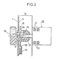
- La figure 3 montre, en coupe, le commutateur de sélection de la figure 2 monté sur le bandeau d'un appareil de cuisson.
- Dans la figure 1, il est représenté un bandeau 1 d'un appareil de cuisson, muni d'un dispositif d'affichage comportant un afficheur 2 et d'un autre dispositif d'affichage comportant un afficheur 3.
- L'afficheur 2 est composé d'un tube fluorescent 2A à secteurs 2' munis de raies lumineuses, ces secteurs étant visibles à travers une zone transparente du bandeau. Cet afficheur assure, par exemple, l'affichage des séquences.
- L'afficheur 3 est composé de voyants lumineux 3A éclairant des secteurs 3' translucides, munis de raies transparentes, et faisant partie du bandeau. Les raies sont alors éclairées par les voyants. Cet afficheur assure, par exemple, l'affichage de la température.
- Derrière le bandeau 1, chaque secteur 2' du tube fluorescent 2A comporte des connexions électriques 4 et chaque voyant lumineux 3A comporte des connexions électriques 5.
- Il est représenté en traits interrompus un commutateur de sélection 10 situé derrière le bandeau, entre un bouton de commande et un commutateur de puissance par exemple, non représentés. Le commutateur de sélection 10 sera décrit plus en détail dans les figures 2 et 3 et le bouton de commande et le commutateur de puissance y seront représentés.
- Sur ce bandeau 1 est également représenté un bouton de commande 6B manoeuvrant un commutateur thermostatique par exemple.
- Dans la figure 2, il est représenté un commutateur 20 qui peut être soit un commutateur de puissance, soit un commutateur thermostatique.
- Ce commutateur 20 comprend des connexions électriques 21 et un axe 22 comportant un méplat 23, cet axe s'engageant dans un bouton de commande 6A.
- Le commutateur de sélection 10 comporte une plaque-support 11 de circuit imprimé munie de pistes 12 reliées à des connexions électriques 13. Ces connexions électriques 13 sont bien entendu reliées électriquement aux connexions électriques 4 du tube 2A ou aux connexions électriques 5 des voyants lumineux 3A.
- Cette plaque-support 11 comporte également des balais 14 qui connectent les pistes 12 entre elles pour allumer les secteurs 2' à raies lumineuses ou les secteurs 3' à raies éclairées de manière appropriée. Ces balais sont enfichés dans une fente 16 d'une pièce porte-balais 15. Cette pièce 15 comporte une partie 17 qui permet de fixer par enclipsage la plaque support de circuit imprimé contre le bandeau 1 comme le montre la figure 3.
- Un crantage 30 poussé par un ressort 31 s'engage dans des rainures 19 de la pièce porte-balais 15, ceci étant également visible en figure 3.
- Une opération de sélection et d'affichage d'une séquence se passe de la manière suivante :
- Un opérateur tourne le bouton 6A qui commande dans ce cas le commutateur de puissance 20 assurant la sélection de la séquence. Le commutateur de sélection 10 commande l'affichage de la séquence par l'intermédiaire des balais 14 qui relient les pistes 12 correspondantes à la séquence choisie.
- Ces pistes alimentent le tube fluorescent 2A et le secteur 2' à raies lumineuses correspondant s'allume, les autres étant éteints.
- Une opération de sélection et d'affichage d'une température se passe de la manière suivante :
- Un opérateur tourne le bouton 6B qui commande dans ce cas le commutateur thermostatique réglant la température de l'appareil. Le commutateur de sélection 10 commande l'affichage de la température par l'intermédiaire des balais 14 qui relient les pistes 12 correspondantes à la température choisie. Ces pistes alimentent les voyants lumineux 3A et les secteurs 3' à raies éclairées s'allument graduellement, c'est-à-dire qu'à partir d'une extrémité et à une température basse aucun secteur n'est allumé et au fur et à mesure que la température augmente, le secteur adjacent s'allume puis le secteur adjacent à ce dernier et ainsi de suite pour réaliser une bande lumineuse de longueur variable. Chaque secteur représente, par exemple, une augmentation de température de 25 °C.
Claims (5)
Applications Claiming Priority (2)
| Application Number | Priority Date | Filing Date | Title |
|---|---|---|---|
| FR8403756 | 1984-03-12 | ||
| FR8403756A FR2561017B1 (fr) | 1984-03-12 | 1984-03-12 | Dispositif d'affichage des sequences ou de la temperature d'un appareil de cuisson |
Publications (2)
| Publication Number | Publication Date |
|---|---|
| EP0156717A1 EP0156717A1 (fr) | 1985-10-02 |
| EP0156717B1 true EP0156717B1 (fr) | 1989-01-11 |
Family
ID=9301921
Family Applications (1)
| Application Number | Title | Priority Date | Filing Date |
|---|---|---|---|
| EP19850400457 Expired EP0156717B1 (fr) | 1984-03-12 | 1985-03-08 | Dispositif d'affichage des séquences ou de la température d'un appareil de cuisson |
Country Status (3)
| Country | Link |
|---|---|
| EP (1) | EP0156717B1 (fr) |
| DE (1) | DE3567532D1 (fr) |
| FR (1) | FR2561017B1 (fr) |
Families Citing this family (10)
| Publication number | Priority date | Publication date | Assignee | Title |
|---|---|---|---|---|
| DE4318845C3 (de) * | 1993-06-07 | 1998-07-09 | Thielmann Ag Kg | Drehmomentübertragungseinrichtung für einen Herd |
| DE29502768U1 (de) * | 1995-02-20 | 1995-04-06 | Bosch-Siemens Hausgeräte GmbH, 81669 München | Einbauherd mit eigenständiger Kochmulde |
| DE10138888A1 (de) | 2001-08-08 | 2003-02-20 | Bsh Bosch Siemens Hausgeraete | Gargerät |
| DE10202049A1 (de) * | 2002-01-18 | 2003-07-31 | Faude Consulting Gmbh R | Schaltanordnung für eine Haushaltsmaschine oder dergleichen |
| DE10203509B4 (de) * | 2002-01-30 | 2005-01-13 | Whirlpool Corp., Benton Harbor | Rastvorrichtung für einen mehrstufigen Drehschalter |
| DE10234925A1 (de) * | 2002-07-31 | 2004-02-19 | BSH Bosch und Siemens Hausgeräte GmbH | Drehwähler |
| WO2014102043A1 (fr) | 2012-12-26 | 2014-07-03 | Arcelik Anonim Sirketi | Dispositif de cuisson contenant un élément de commande |
| WO2018007155A1 (fr) * | 2016-07-04 | 2018-01-11 | Arcelik Anonim Sirketi | Appareil ménager comportant un organe de commande rotatif étagé |
| TR201619833A1 (tr) * | 2016-12-28 | 2018-07-23 | Arcelik As | Düğme İçeren Bir Pişirici Cihaz |
| WO2023140800A1 (fr) * | 2021-12-27 | 2023-07-27 | Femas Metal San. Ve Tic. A.S. | Four doté d'un élément d'éclairage |
Family Cites Families (4)
| Publication number | Priority date | Publication date | Assignee | Title |
|---|---|---|---|---|
| FR2161167A5 (fr) * | 1971-11-16 | 1973-07-06 | Thomson Brandt | |
| US4121204A (en) * | 1976-12-14 | 1978-10-17 | General Electric Company | Bar graph type touch switch and display device |
| DE2848824C2 (de) * | 1978-11-10 | 1990-02-15 | Diehl Gmbh & Co, 8500 Nuernberg | Anordnung zur Leistungssteuerung |
| FR2489485A1 (fr) * | 1980-08-28 | 1982-03-05 | Martin Usines Fonderie Arthur | Dispositif de commande d'un four domestiq ue |
-
1984
- 1984-03-12 FR FR8403756A patent/FR2561017B1/fr not_active Expired
-
1985
- 1985-03-08 DE DE8585400457T patent/DE3567532D1/de not_active Expired
- 1985-03-08 EP EP19850400457 patent/EP0156717B1/fr not_active Expired
Also Published As
| Publication number | Publication date |
|---|---|
| FR2561017B1 (fr) | 1987-11-27 |
| EP0156717A1 (fr) | 1985-10-02 |
| DE3567532D1 (en) | 1989-02-16 |
| FR2561017A1 (fr) | 1985-09-13 |
Similar Documents
| Publication | Publication Date | Title |
|---|---|---|
| EP0156717A1 (fr) | Dispositif d'affichage des séquences ou de la température d'un appareil de cuisson | |
| JP5963084B2 (ja) | スイッチ | |
| JP2000508776A (ja) | 指針計器 | |
| US6572245B2 (en) | Nightlight with dynamic image effect | |
| EP0484795A1 (fr) | Rasoir électrique | |
| US20030184999A1 (en) | Light emitting diode (LED) flashlight | |
| US5826969A (en) | Illuminating screw driver | |
| FR2486856A1 (fr) | Appareil electrique, par exemple un rasoir, muni d'un mecanisme de comptage | |
| US4105314A (en) | Hand crank generator-powered rotary slide projector | |
| EP0756967A1 (fr) | Indicateur pour tableau de bord | |
| US2694338A (en) | Clock face projecting device | |
| US2604814A (en) | Lighting attachment for stereoscopic viewers | |
| EP2535785A1 (fr) | Dispositif de commande d'un appareil électroménager | |
| FR2580423A1 (fr) | Dispositif eclaire pour le reglage d'une grandeur electrique | |
| US2066145A (en) | Changeable color electric lamp | |
| US4459448A (en) | Double pull double throw switch | |
| FR2810722A1 (fr) | Dispositif lumineux associe a la position des mains d'un utilisateur | |
| JP6168455B2 (ja) | スイッチ | |
| FR2591720A1 (fr) | Commutateur rotatif pour cuisinieres a gaz | |
| ATE104419T1 (de) | Automatische zuendvorrichtung fuer geraete mit gaskochmulde. | |
| US2498943A (en) | Illuminated switch socket | |
| BE1015041A3 (fr) | Plaque-chassis pour mecanismes electriques et electroniques. | |
| FR2799627A3 (fr) | Miroir, en particulier a usage domestique | |
| JP4079846B2 (ja) | システムキッチン | |
| KR910001256Y1 (ko) | 전자기기용 모드 선택스위치의 발광다이오드 표시장치 |
Legal Events
| Date | Code | Title | Description |
|---|---|---|---|
| PUAI | Public reference made under article 153(3) epc to a published international application that has entered the european phase |
Free format text: ORIGINAL CODE: 0009012 |
|
| AK | Designated contracting states |
Designated state(s): BE DE FR GB IT NL |
|
| 17P | Request for examination filed |
Effective date: 19860319 |
|
| 17Q | First examination report despatched |
Effective date: 19860721 |
|
| D17Q | First examination report despatched (deleted) | ||
| GRAA | (expected) grant |
Free format text: ORIGINAL CODE: 0009210 |
|
| AK | Designated contracting states |
Kind code of ref document: B1 Designated state(s): BE DE FR GB IT NL |
|
| ITF | It: translation for a ep patent filed | ||
| REF | Corresponds to: |
Ref document number: 3567532 Country of ref document: DE Date of ref document: 19890216 |
|
| GBT | Gb: translation of ep patent filed (gb section 77(6)(a)/1977) | ||
| PLBE | No opposition filed within time limit |
Free format text: ORIGINAL CODE: 0009261 |
|
| STAA | Information on the status of an ep patent application or granted ep patent |
Free format text: STATUS: NO OPPOSITION FILED WITHIN TIME LIMIT |
|
| 26N | No opposition filed | ||
| PGFP | Annual fee paid to national office [announced via postgrant information from national office to epo] |
Ref country code: GB Payment date: 19930225 Year of fee payment: 9 Ref country code: DE Payment date: 19930225 Year of fee payment: 9 |
|
| PGFP | Annual fee paid to national office [announced via postgrant information from national office to epo] |
Ref country code: BE Payment date: 19930301 Year of fee payment: 9 |
|
| ITTA | It: last paid annual fee | ||
| PGFP | Annual fee paid to national office [announced via postgrant information from national office to epo] |
Ref country code: NL Payment date: 19930331 Year of fee payment: 9 |
|
| PG25 | Lapsed in a contracting state [announced via postgrant information from national office to epo] |
Ref country code: GB Effective date: 19940308 |
|
| PG25 | Lapsed in a contracting state [announced via postgrant information from national office to epo] |
Ref country code: BE Effective date: 19940331 |
|
| BERE | Be: lapsed |
Owner name: CIE EUROPEENNE POUR L'EQUIPEMENT MENAGER CEPEM Effective date: 19940331 |
|
| PG25 | Lapsed in a contracting state [announced via postgrant information from national office to epo] |
Ref country code: NL Effective date: 19941001 |
|
| GBPC | Gb: european patent ceased through non-payment of renewal fee |
Effective date: 19940308 |
|
| NLV4 | Nl: lapsed or anulled due to non-payment of the annual fee | ||
| PG25 | Lapsed in a contracting state [announced via postgrant information from national office to epo] |
Ref country code: DE Effective date: 19941201 |
|
| PGFP | Annual fee paid to national office [announced via postgrant information from national office to epo] |
Ref country code: FR Payment date: 19950324 Year of fee payment: 11 |
|
| PG25 | Lapsed in a contracting state [announced via postgrant information from national office to epo] |
Ref country code: FR Effective date: 19961129 |
|
| REG | Reference to a national code |
Ref country code: FR Ref legal event code: ST |