EP0156074A2 - Positive displacement diaphragm pump employing displacer valves - Google Patents
Positive displacement diaphragm pump employing displacer valves Download PDFInfo
- Publication number
- EP0156074A2 EP0156074A2 EP84308711A EP84308711A EP0156074A2 EP 0156074 A2 EP0156074 A2 EP 0156074A2 EP 84308711 A EP84308711 A EP 84308711A EP 84308711 A EP84308711 A EP 84308711A EP 0156074 A2 EP0156074 A2 EP 0156074A2
- Authority
- EP
- European Patent Office
- Prior art keywords
- pump
- diaphragm
- pumping
- chamber
- chambers
- Prior art date
- Legal status (The legal status is an assumption and is not a legal conclusion. Google has not performed a legal analysis and makes no representation as to the accuracy of the status listed.)
- Granted
Links
Images

Classifications
-
- F—MECHANICAL ENGINEERING; LIGHTING; HEATING; WEAPONS; BLASTING
- F04—POSITIVE - DISPLACEMENT MACHINES FOR LIQUIDS; PUMPS FOR LIQUIDS OR ELASTIC FLUIDS
- F04B—POSITIVE-DISPLACEMENT MACHINES FOR LIQUIDS; PUMPS
- F04B45/00—Pumps or pumping installations having flexible working members and specially adapted for elastic fluids
- F04B45/04—Pumps or pumping installations having flexible working members and specially adapted for elastic fluids having plate-like flexible members, e.g. diaphragms
-
- F—MECHANICAL ENGINEERING; LIGHTING; HEATING; WEAPONS; BLASTING
- F04—POSITIVE - DISPLACEMENT MACHINES FOR LIQUIDS; PUMPS FOR LIQUIDS OR ELASTIC FLUIDS
- F04B—POSITIVE-DISPLACEMENT MACHINES FOR LIQUIDS; PUMPS
- F04B43/00—Machines, pumps, or pumping installations having flexible working members
- F04B43/02—Machines, pumps, or pumping installations having flexible working members having plate-like flexible members, e.g. diaphragms
- F04B43/06—Pumps having fluid drive
- F04B43/073—Pumps having fluid drive the actuating fluid being controlled by at least one valve
- F04B43/0733—Pumps having fluid drive the actuating fluid being controlled by at least one valve with fluid-actuated pump inlet or outlet valves; with two or more pumping chambers in series
Landscapes
- Engineering & Computer Science (AREA)
- Mechanical Engineering (AREA)
- General Engineering & Computer Science (AREA)
- Reciprocating Pumps (AREA)
- Separation Using Semi-Permeable Membranes (AREA)
- Details Of Reciprocating Pumps (AREA)
Abstract
Description
- As background to the present invention, reference may be made to our co-pending European patent application EP-A-111540 (W083/04242) claiming the priority of U.S. patent application Serial No.385,176.
- The present invention relates generally to air operated, positive displacement diaphragm pumps that are submerged in the liquid to be discharged, and more particularly to diaphragm pumps employing a plurality of displacer valves.
- Diverse diaphragm pumps have been used in the prior art to withdraw liquid from a receptacle through an inlet port and discharge same through an outlet port. The diaphragm usually divides the pump housing into a supply chamber and a pressure chamber. A first check valve regulates flow into the supply chamber, and a second check valve controls the flow therefrom. Electrical or hydraulic signals are supplied to an externally situated operator, such as a piston, for controlling the movement of a diaphragm or membrane within the pump casing. The movement of the diaphragm forces the pressurized fluid out of the supply chamber and past the second check valve. Representative reciprocating diaphragm pumps are shown in U.S. Patents 3,285,182, granted November 15, 1966 to H.E. Pinkerton, U.S. Patent 3,814,548, granted June 4, 1974 to Warren E. Rupp, and U.S. Patent 4,021,164, granted May 3, 1977 to Hans Peter Tell,
- Known reciprocating diaphragm pumps of low capacity, however, have very little, if any, self-priming action. Such pumps therefore must be kept at a level close to, or below, the liquid level of the container from which the liquid is being pumped. Also, check valves of known reciprocating pumps exhibit a tendency to leak. While the leakage is a minor problem when relatively large quantities of liquid are being pumped, the problem assumes far greater importance when the quantities being pumped are but a few milliliters over an extended period of time and when exact metering is required.
- The first of the aforementioned shortcomings of known reciprocating diaphragm pumps was remedied by the diaphragm pump, shown in detail in FIGS. 2-5 of aforementioned, co-pending patent application Serial No. 385,176. To illustrate, the diaphragm pump shown and described in the co-pending application responds to control pulses of low pressure air delivered from a pulse generator controlled by pneumatic logic circuitry; the low pressure air is readily available in industrial plants and represents a marked cost saving over known electrical and hydraulic control systems. Also, the driving membrane, pumping membrane, and displacer of the co-pending application function effectively to discharge small quantities of liquid at a selected rate; by manipulation of a resistor in the logic circuitry, the rate can be varied. Additionally, the diaphragm pump of the co-pending application can be submerged in the liquid to be discharged, even a corrosive liquid, and function satisfactorily over extended periods of time and with constant, reproducible discharge rates.
- While the diaphragm pump of the aforesaid co-pending application represents a significant advance over known diaphragm pumps, extensive field tests of said pump, while handling corrosive liquids such as tin compounds for hot coating glass bottles, suggested even further refinements in the pump design would be desirable. For example, the instant diaphragm pump obviates the use of an inlet check valve and an outlet check valve, replacing such valves by a pair of positively driven displacer valves. The pair of positively driven valves, when coupled with the conventional positively driven diaphragm valve, coact to force a metered amount of corrosive liquid through the pump body in a sequence of steps. The concept of the three positively driven displacer valves used in the instant diaphragm pump can be extended to four or more displacer valves, as desired or as needed, for successfully low volume operation.
- Additionally, the instant positive displacement diaphragm pump can be controlled by a pneumatic pulse generator comprising a logic circuit of simplified design. The instant positive displacement diaphragm pump is compatible with the logic circuit shown in"FIG. 6 of co-pending application S.N. 385,176, and can function in concert with other pneumatic and pure-fluid logic circuits with equal facility.
- The present invention contemplates a positive displacement diaphragm pump employing three, or more, displacer valves for drawing liquid into the pump body, pressurizing same, and discharging same at a constant, low volume flow rate over extended periods of time.
- The present positive displacement diaphragm pump is reliable, leak-proof, and can withstand submersion in corrosive liquids. The problem of leakage associated with known check valves, such as spring loaded ball valves, has been obviated.
- Furthermore, the present positive displacement diaphragm pump is substantially self-priming in operation, provides reproducible results over extended periods of time, operates reliably with a low pressure head, and yet discharges minutes quantities of liquid in a series of discrete pulses.
- Lastly, the present positive displacement diaphragm pump can be operated by low pressure air pulses supplied thereto from known pulse generators comprising a pneumatic logic circuit of simplified design. Additionally, even in the unlikely instance of membrane failure, the air pressure is sufficient to keep the corrosive liquid from entering the pulse generator and destroying same.
- Yet other advantages of the present positive displacement diaphragm pump will become readily apparent to the skilled artisan from the appended drawings and the accompanying detailed description.
- In the accompanying drawings :-
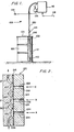
- FIG. 1 is a side elevational view of an air operated diaphragm pump system constructed in accordance with the principles of the instant invention, said system being shown in operative association with a drum filled with liquid;
- FIG. 2 is a vertical cross-sectional view of a first embodiment of a unique diaphragm pump utilized in the system of FIG. 1, such view being taken on an enlarged scale;
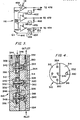
- FIG. 3 is a full scale vertical cross-sectional view of a second embodiment of a unique diaphragm pump utilized in the system of FIG. 1;
- FIG. 4 is a top plan view of the diaphragm pump of FIG. 3;
- FIG. 5 is an exploded perspective view of a displacer valve utilized within the diaphragm pump shown in FIGS. 3-4;
- FIG. 6 is a vertical cross-sectional view of a third embodiment of a unique diaphragm pump utilized in the system of FIG. 1;
- FIG. 7 is a top plan view of the diaphragm pump shown in FIG. 6; and
- FIG. 8 is a schematic representation of the pneumatic logic circuitry that forms a pulse generator for operating the various embodiments of the diaphragm pump.
- Turning now to the drawings, FIG. 1 depicts a large
metallic drum 100 having a capacity of 80 gallons. The liquid level line is indicated bydotted line 102, and a fragment of the drum has been removed to show the interior thereof. Alid 104 seals the open upper end of thedrum 100, and anaperture 106 is formed through the lid. - An air operated, diaphragm pump assembly, indicated generally by
reference numeral 108, is operatively connected to the drum for draining its contents. Theassembly 108 comprises aconventional diaphragm pump 110 positioned on, or closely adjacent to, the bottom ofdrum 100, anextension sleeve 112 projecting upwardly from the pump through theaperture 106, and a-collar 114 secured to the upper end of the extension sleeve. The diaphragm pump assembly further includes apulse generator 116, anair supply line 118 for delivering pressurized or compressed air to the pulse generator, and aconduit 120 which extends from the pulse generator, to collar 114 onextension sleeve 112, and into communication withpump 110.Conduit 120 andsleeve 112 contain three air pulse hoses, one return-pressure hose and the pump delivery hose. The last hose is connected tosight glass 126, and terminates atdelivery point 128.Extension sleeve 112 is more or less rigid and has a liquid tight connection to pump 110. The sleeve protects the hoses in it from attack by the liquid indrum 100.Conduit 120 is flexible and allows the pump to be moved into, and from, the drum. - FIG. 2 depicts schematically a first embodiment of a
diaphragm pump 210 that was intended to be substituted for conventional pump l10 in the air operated pump system of FIG. 1.Pump 210 comprises a body composed of a left hand segment 212 and aright hand segment 214 with a single,flexible membrane 216 disposed therebetween. Three spacedhemispherical chambers channels segment 214. Threadedconnections inlet conduit 236 extends from the lower edge of segment 212 tochamber 218, a first internal conduit 238 extends fromchamber 218 upwardly tochamber 220, a secondinternal conduit 240 extends fromchamber 220 upwardly to chamber 222, and an outlet conduit 242 leads from chamber 222 to the upper edge of segment 212. - The
pump 210 is submerged in the liquid to be pumped, such liquid being retained in a drum or other suitable receptacle. Pulses of air, at a pressure slightly greater than atmospheric air, are delivered in a predetermined sequence to the conduits insegment 214. More specifically, the submersion ofpump 210 forces at least a limited quantity of liquid intochamber 218. Then, when a first pulse of air is delivered from a pulse generator, such as pulse,generator 116, to conduit 224, themembrane 216 is forced to assume a concave shape and force the liquid inchamber 218 through conduit 238 intosecond cavity 220. For the duration of pulse A, the membrane flexing inchamber 218 serves as a check valve to prevent the liquid from flowing back downinlet conduit 236. - When a second pulse B of air is delivered from the pulse generator to conduit 226, the membrane assumes a concave shape and forces the fluid in
chamber 220 throughconduit 240 into a third chamber 222. For the duration of pulse B, the membrane flexing inchamber 220 serves as a check valve to prevent the liquid from flowing downwardly in the pump body. The pulse A may be terminated while B is still operational. - When a third pulse C of air is delivered from the
pulse generator 116 to conduit 228 over one of the three air pulse hoses retained inconduit 120, the membrane assumes a concave shape and forces the fluid in chamber 222 upwardly through conduit 242 for discharge at a remote discharge point. Here again, for the duration of pulse C, the membrane flexing in chamber 222 serves as a check valve to prevent the liquid from flowing downwardly in the pump body. - When the pressure produced by the delivery of air pulses to
conduit 224 is removed, themembrane 216 returns to its unstressed condition andchamber 218 becomes filled with liquid again. Removal of the pressure fromconduit 226 will similarly allow the membrane to return to its unstressed condition andcause chamber 220 to fill with liquid. To complete the pumping cycle, pulses of air are again delivered toconduit 224, removed fromconduit 228, and subsequently delivered toconduit 226. Each operational cycle ofpump 210 will deliver an amount of liquid governed by the volume ofchamber 220. - Whereas
chambers pump 210 shown in FIG. 2 are equal in volume, it should be noted that this size relationship may be altered to fit different operational requirements. To illustrate, if chamber 222 were made to be one-half the volume ofchamber 220, the pump would deliver one-half of its liquid output upon the delivery of pulses of air pressure toconduit 226, and the other half of its liquid output (for each cycle of operation) upon the delivery of pulses of air pressure toconduit 230. In the event that the pump was formed with more than three chambers, for example "n" chambers, the liquid output for each cycle of operation could be divided into n-1 pulses per pump cycle, by the judicious selection of the chamber volumes. - Whereas the
pump 210 functions satisfactorily, and is superior to known diaphragm operated pumps, themembrane 216 poses some problems. Thus, when themembrane 216 is fabricated of natural rubber, the pump works well for several days, but the pump capacity diminishes gradually thereafter as slack in the membrane increases. When themembrane 216 is fabricated from a plastic, such as Viton , the membrane stretches even more quickly and the pump capacity diminishes in the same fashion. Techniques such as pre-stretching the membrane and/or providing a spring return arrangement for the membrane failed to solve this problem. - FIG. 3 depicts schematically a second embodiment of a
diaphragm pump 310 that was substituted forpump 110 in the air operated pump system of FIG. 1.Pump 310 represents an improvement overpump 210 and solves the longevity problem associated with thediaphragm 216 inpump 210. Additionally, pump 310 positively returns the diaphragm to its unstressed, at rest position, without resorting to metal biasing springs or pre-stretched membranes. -
Pump 310 comprises a body composed of aleft hand segment 312 and aright hand segment 314 with a single,flexible pumping membrane 316 disposed therebetween. First, second and third spaced pumpingchambers segment 314. Aninlet conduit 324 extends from the lower edge ofsegment 314 upwardly tofirst pumping chamber 318, and a firstinternal conduit 326 extends betweenchamber 318 andsecond pumping chamber 320. A secondinternal conduit 328 extends betweenchamber 320 andthird pumping chamber 322, and anoutlet conduit 330 extends betweenchamber 322 and the upper end of the pump housing. An enlarged threadedport 332 is formed at the end ofconduit 330 to receive a threaded hose or pipe (not shown) to transmit the liquid to a remote location for discharge. - A first
intermediate chamber 334 is defined in the lower end ofsegment 312 between small drivingmembrane 336 and pumpingmembrane 316. Second and thirdintermediate chambers segment 312 respectively between small drivingmembranes membrane 316. A vertically orientedpassage 346 extends downwardly from the upper end ofsegment 312 throughchambers passage 346, all of the membranes are subjected to the same pressure. Thesmall driving membranes - A
first pressure chamber 348 is defined between drivingmembrane 336 and a cavity formed in the lower end ofsegment 312; afirst control conduit 350 extends from the top ofsegment 312 directly into the cavity.Control conduit 350 is not shown in FIG. 3, but is shown in FIG. 4. Asecond pressure chamber 352 is defined between drivingmembrane 340 and a cavity formed in the middle ofsegment 312; asecond control conduit 354 extends from the top ofsegment 312 directly into the cavity.Control conduit 354 is not shown in FIG. 3, but is shown in FIG. 4. Athird pressure chamber 356 is defined between drivingmembrane 344 and a cavity formed in the upper end ofsegment 312. Athird control conduit 358 extends from the top ofsegment 312 directly into the upper cavity, as shown in FIG. 3. - A first displacer valve, indicated generally by
reference number 360, is utilized to force the liquid from pumpingchamber 318 viainternal conduit 326 intosecond pumping chamber 320. A second, identical displacer valve, indicated generally byreference numeral 362, is utilized to force the liquid from pumpingchamber 320 viainternal conduit 328 intothird pumping chamber 322. A third identical displacer valve, indicated generally byreference numeral 364, is utilized to force the liquid fromchamber 322 viaconduit 330 throughport 332 into a hose or pipe (not shown) for discharge at a remote location. - FIG. 5 shows an exploded perspective view of
representative displacer valve 360.Displacer valves aud 364 are identical in construction and function. -
Displacer valve 360 includes acylindrical cap 366 with an enlargedannular shoulder 368 that guides the movement of the cap within pumpingchamber 318. Abutton 370 of a resilient, chemically inert material fits within anaperture 375 in the working face of the valve, and acentral bore 374 extends into, but not through, thecap 366; the bore is shown in dotted outline. The valve also comprises aspacer 377 with abore 376 extending therethrough, anannular clamping plate 378 with ahole 379 therethrough, and anelongated screw 380 with an enlarged head. Aslot 381 is formed in the head to admit a screwdriver or similar tool. - The shank of
screw 380 extends through theaperture 379 in clampingplate 378, through a smallcentral aperture 384 in drivingdiaphragm 336, throughbore 376 inspacer 377, through a small aperture in pumpingdiaphragm 316, and into thebore 374 incap 366. Thedisplacer valve 360 employs thescrew 380 to secure the valve to the diaphragms, as well as to join the components of the valve into a unitary structure. -
Pump 310, as shown in FIGS. 3-5, functions in the following manner. A reference pressure is introduced overpassage 346 to pressurize theintermediate chambers lower pumping chamber 318 to prime same. A first control pulse of air is then introduced atconduit 350, which momentarily raises the pressure in thefirst pressure chamber 348 to a level greater than that of the intermediate, or reference,chamber 334. The drivingdiaphragm 336 flexes towarddiaphragm 316 and the cap moves rightward withinchamber 318 until thebutton 370 abuts against the wall defining the chamber. The liquid previously retained within pumpingchamber 318 is forced throughinternal conduit 326 intosecond pumping chamber 320. The control pulse is of sufficient duration to retain the button against the chamber wall to prevent leakage back intofirst pumping chamber 318 andinlet conduit 324. - After the
second pumping chamber 320 is filled, a second control pulse of air is introduced atconduit 354, which momentarily raises the pressure in thesecond pressure chamber 352 to a level greater than that of the intermediate, or reference,chamber 338. The drivingdiaphragm 340 flexes toward pumpingdiaphragm 316 and thecap 366 moves rightward withinchamber 320 until the button abuts against the wall defining the chamber. The liquid previously retained within pumpingchamber 320 is forced throughinternal conduit 328 intothird pumping chamber 322. The control pulse appearing atconduit 324 is of sufficient duration to retain the button against the chamber wall to prevent leakage; the control pulse appearing atconduit 350 may be terminated. - After the
third pumping chamber 322 is filled, a third control pulse of air is introduced atconduit 358, which momentarily raises the pressure in thethird pressure chamber 356 to a level greater than that of the intermediate, or reference,chamber 342. The drivingdiaphragm 344 flexes toward pumpingdiaphragm 316 and thecap 366 moves rightward withinchamber 322 until the button abuts against the wall defining the chamber. The liquid previously retained withinthird pumping chamber 322 is forced throughoutlet conduit 330 andoutlet port 332 into a hose (not shown) to be discharged at a remote location. - FIGS. 6-7 depict a
third embodiment 410 of a diaphragm operated pump that can be substituted forpump 110 in the air operated pump system of FIG. 1. Pump 410 functions in much the same manner aspump 310, described in detail above with particular reference to FIGS. 3-5. However, whilepump 310 relies upon onepumping diaphragm 316 extending throughout the pump housing, pump 410 utilizes threesmaller pumping diaphragms diaphragms pump 310 relies upon a pump body formed of but twosegments pump 410 is formed of a plurality ofsmaller segments gasket 432 is located betweenadjacent segments Nuts 436 are advanced on the opposed ends of the rods to draw the multiplicity of segments together, and acollar 438 at the upper end ofsegment 430 is secured to theextension sleeve 112 shown in FIG. 1. - While
pump 310 has its unitary pumping diaphragm oriented vertically, pump 410 employes three horizontally disposed, and smaller, pumpingdiaphragms diaphragms pump 310 has pumpingchambers chambers chamber 444 is oriented 180° out of phase with the other two pumping chambers. - While
pump 310 functions satisfactorily, a problem was encountered during field tests with leakage between the pump andextension sleeve 112. The leakage problem was compounded by the corrosive nature of the liquid being pumped. Thus, the preferred configuration ofpump 410 was evolved, which overcame the leakage problem yet functioned with results comparable to those obtained withpump 310. - Since
pumps - FIG. 8 reveals the logic circuit that functions as a
pulse generator 116 for the air operated pump system. The pulse generator delivers low pressure air pulses of the requisite duration, and magnitude, to knownpumps 110, as well as to theunique pumps -
Pulse generator 116, is comprised of well known, commercially available fluid logic elements, such as those sold by Samsomatic Ltd., Fairfield, New Jersey of Samson AG of Frankfort, W. Germany. Amanual switch 446 is incorporated into the pulse generator; such switch, which is shown in its operative position, is moved to either a venting position or a closed position (as shown) when the contents of areceptacle 100 have been drained and a new receptacle is being positioned to receivepump -
Pulse generator 116 which is pressurized overair supply line 118, includes pneumatic switches 448 and 466 and also a so-called Schmitt-trigger 458. Switches 448 and 466 change state at a pressure somewhat above zero pressure and somewhat below the maximum system pressure. The Schmitt-trigger 458 changes state at exactly the predetermined low and high pressure levels. High pressure at the control port of these switches causes pressure venting at the switch outlet whereas no pressure at the control port means ,full, pressure at the outlet. Switch 448 supplies pressure tochamber 454 in pump 410 (or tochamber 348 in pump 310). - The fluid under pressure enters
volume 452 through avariable resistor 450 and is connected overconduit 456 to Schmitt-trigger 458. After a certain time lapse (as determined byresistor 450 and volume 452), the pressure involume 452 reaches a sufficient level and this pressure is reflected at the control port of the Schmitt-trigger. This increased pressure signal causes the trigger to change state so that the air pressure inchamber 476 ofpump 410 will be vented through the Schmitt-trigger. Also, the air fromvolume 462 now vents through fixedresistor 460 causing the pressure involume 462 and at the control port of switch 466 to drop to zero. - Switch 466 now provides a pressurized discharge at its outlet, causing pressure in
chamber 472 in pump 410 (orchamber 352 in pump 310) to increase. Pressure will now build up withinvolume 470 throughresistor 468, which after a time period determined byresistor 468 andvolume 470, will produce sufficient air pressure at the control port of switch 448 to change its state. This will vent air pressure frompump chamber 454 inpump 410. - The above-described half cycle is now repeated, however with the pressurizing and venting steps reversed, to complete a full cycle and to cause the pumping action of pump 410 (or 310).
- Of course, it will be appreciated that all the switches might be Schmitt-triggers and all of the resistors might be variable resistors. Additionally, when a high speed of the pulse cycle is needed, it may be advantageous to bypass
resistor 450 with a pneumatic check valve (indicated in dotted lines in FIG. 8) which allows unrestricted air flow fromvolume 456 to the outlet of switch 448, but restricted flow in the opposite direction. This check valve will cause an overlap in pressure-release fromchamber 454 and pressure build-up inchamber 476. This does not cause pump valve leakage, as the middle valve is closed at this moment. - The
sight glass 126 on the side of the cabinet housing thepulse generator 116 provides a visual indication that the system is functioning properly. - Numerous modifications and revisions may occur to the skilled artisan. For example, the logic circuitry may assume diverse forms, including pure fluid components with the necessary number of amplifiers. Furthermore, although three displacer valves are disclosed, four or more may be utilized in conjunction with pneumatic logic circuitry capable of delivering four or more control pulses in the proper sequence and with the proper timing.
- The diaphragm pump of the present invention can be used for a wide variety of purposes. As already. indicated, one such purpose is the supply of coating material for the hot coating of glass bottles. Reference may be made in this connection to US-A-4130673, US-A-4144362, EP-A-0103019 and EP-A-0132024. The invention also embraces a method of coating glass which includes the step of supplying coating material with a pump according to this invention.
Claims (8)
Priority Applications (1)
| Application Number | Priority Date | Filing Date | Title |
|---|---|---|---|
| AT84308711T ATE54196T1 (en) | 1983-12-28 | 1984-12-14 | POSITIVE DISPLACEMENT DIAPHRAGM PUMP USING DISPLACEMENT VALVES. |
Applications Claiming Priority (2)
| Application Number | Priority Date | Filing Date | Title |
|---|---|---|---|
| US06/566,363 US4583920A (en) | 1983-12-28 | 1983-12-28 | Positive displacement diaphragm pumps employing displacer valves |
| US566363 | 1983-12-28 |
Publications (3)
| Publication Number | Publication Date |
|---|---|
| EP0156074A2 true EP0156074A2 (en) | 1985-10-02 |
| EP0156074A3 EP0156074A3 (en) | 1986-12-17 |
| EP0156074B1 EP0156074B1 (en) | 1990-06-27 |
Family
ID=24262572
Family Applications (1)
| Application Number | Title | Priority Date | Filing Date |
|---|---|---|---|
| EP84308711A Expired - Lifetime EP0156074B1 (en) | 1983-12-28 | 1984-12-14 | Positive displacement diaphragm pump employing displacer valves |
Country Status (21)
| Country | Link |
|---|---|
| US (1) | US4583920A (en) |
| EP (1) | EP0156074B1 (en) |
| JP (1) | JPS60228781A (en) |
| KR (1) | KR920002157B1 (en) |
| AT (1) | ATE54196T1 (en) |
| AU (1) | AU571297B2 (en) |
| BR (1) | BR8406716A (en) |
| CA (1) | CA1239831A (en) |
| DE (1) | DE3482600D1 (en) |
| DK (1) | DK626684A (en) |
| ES (1) | ES538879A0 (en) |
| GR (1) | GR82495B (en) |
| IL (1) | IL73612A (en) |
| IN (1) | IN161810B (en) |
| MX (1) | MX163116B (en) |
| NO (1) | NO168265C (en) |
| NZ (1) | NZ210692A (en) |
| PH (1) | PH21305A (en) |
| PT (1) | PT79636B (en) |
| TR (1) | TR23305A (en) |
| ZA (1) | ZA849437B (en) |
Cited By (1)
| Publication number | Priority date | Publication date | Assignee | Title |
|---|---|---|---|---|
| GB2235256A (en) * | 1989-06-22 | 1991-02-27 | Thomas John Mcneel Robertson | Flexible chamber pump |
Families Citing this family (39)
| Publication number | Priority date | Publication date | Assignee | Title |
|---|---|---|---|---|
| IL77935A (en) * | 1986-02-19 | 1990-04-29 | Tmb Fertilizer Pumps | Liquid driven reciprocating pump |
| US5098377A (en) * | 1988-09-06 | 1992-03-24 | Baxter International Inc. | Multimodal displacement pump and dissolution system for same |
| US4874297A (en) * | 1988-12-19 | 1989-10-17 | Collins Arthur R | Radial pump |
| US5205722A (en) * | 1991-06-04 | 1993-04-27 | Hammond John M | Metering pump |
| US5371828A (en) * | 1991-08-28 | 1994-12-06 | Mks Instruments, Inc. | System for delivering and vaporizing liquid at a continuous and constant volumetric rate and pressure |
| AT399026B (en) * | 1992-10-13 | 1995-03-27 | Avl Verbrennungskraft Messtech | DEVICE FOR CONTROLLING AND / OR MOVING FLUIDS |
| US5499909A (en) * | 1993-11-17 | 1996-03-19 | Aisin Seiki Kabushiki Kaisha Of Kariya | Pneumatically driven micro-pump |
| US5934885A (en) * | 1994-10-07 | 1999-08-10 | Bayer Corporation | Reagent pump assembly |
| IL115327A (en) * | 1994-10-07 | 2000-08-13 | Bayer Ag | Diaphragm pump |
| US5698262A (en) * | 1996-05-06 | 1997-12-16 | Libbey-Owens-Ford Co. | Method for forming tin oxide coating on glass |
| US6350110B1 (en) * | 2000-03-31 | 2002-02-26 | B&G International | Multiport metering pump |
| DE10224750A1 (en) | 2002-06-04 | 2003-12-24 | Fresenius Medical Care De Gmbh | Device for the treatment of a medical fluid |
| US7458222B2 (en) * | 2004-07-12 | 2008-12-02 | Purity Solutions Llc | Heat exchanger apparatus for a recirculation loop and related methods and systems |
| US7717682B2 (en) * | 2005-07-13 | 2010-05-18 | Purity Solutions Llc | Double diaphragm pump and related methods |
| US8197231B2 (en) | 2005-07-13 | 2012-06-12 | Purity Solutions Llc | Diaphragm pump and related methods |
| US10537671B2 (en) | 2006-04-14 | 2020-01-21 | Deka Products Limited Partnership | Automated control mechanisms in a hemodialysis apparatus |
| CA2970214C (en) * | 2006-04-14 | 2021-08-17 | Deka Products Limited Partnership | System for pumping a biological fluid |
| JP2008002335A (en) * | 2006-06-21 | 2008-01-10 | Kimoto Denshi Kogyo Kk | Liquid feed pump |
| US8409441B2 (en) | 2007-02-27 | 2013-04-02 | Deka Products Limited Partnership | Blood treatment systems and methods |
| US8042563B2 (en) | 2007-02-27 | 2011-10-25 | Deka Products Limited Partnership | Cassette system integrated apparatus |
| EP2131889B1 (en) | 2007-02-27 | 2019-01-02 | Deka Products Limited Partnership | Hemodialysis systems and methods |
| US20080253911A1 (en) | 2007-02-27 | 2008-10-16 | Deka Products Limited Partnership | Pumping Cassette |
| US8038640B2 (en) * | 2007-11-26 | 2011-10-18 | Purity Solutions Llc | Diaphragm pump and related systems and methods |
| US8192401B2 (en) | 2009-03-20 | 2012-06-05 | Fresenius Medical Care Holdings, Inc. | Medical fluid pump systems and related components and methods |
| CA2767668C (en) | 2009-07-15 | 2017-03-07 | Fresenius Medical Care Holdings, Inc. | Medical fluid cassettes and related systems and methods |
| EP2290354B1 (en) | 2009-08-25 | 2019-07-24 | Hach Lange GmbH | Process analyser |
| US9624915B2 (en) | 2011-03-09 | 2017-04-18 | Fresenius Medical Care Holdings, Inc. | Medical fluid delivery sets and related systems and methods |
| EP3006059B1 (en) | 2011-04-21 | 2017-09-27 | Fresenius Medical Care Holdings, Inc. | Medical fluid pumping systems and related devices and methods |
| EP2714134B1 (en) | 2011-05-24 | 2017-05-10 | DEKA Products Limited Partnership | Hemodialysis system |
| US9610392B2 (en) | 2012-06-08 | 2017-04-04 | Fresenius Medical Care Holdings, Inc. | Medical fluid cassettes and related systems and methods |
| US9500188B2 (en) | 2012-06-11 | 2016-11-22 | Fresenius Medical Care Holdings, Inc. | Medical fluid cassettes and related systems and methods |
| US9561323B2 (en) | 2013-03-14 | 2017-02-07 | Fresenius Medical Care Holdings, Inc. | Medical fluid cassette leak detection methods and devices |
| US10117985B2 (en) | 2013-08-21 | 2018-11-06 | Fresenius Medical Care Holdings, Inc. | Determining a volume of medical fluid pumped into or out of a medical fluid cassette |
| EP3155263B1 (en) | 2014-06-16 | 2021-03-17 | Flow Control LLC. | Diaphragm pump utilizing duckbill valves, multi-directional ports and flexible electrical connectivity |
| US11125223B2 (en) * | 2014-09-29 | 2021-09-21 | Volvo Truck Corporation | Reciprocating machine with cylinder having collector groove |
| DE102016015207A1 (en) * | 2016-12-21 | 2018-06-21 | Fresenius Medical Care Deutschland Gmbh | Actuating device and method for operating an actuating device and diaphragm pump with an actuating device and a diaphragm pump device and a blood treatment device with a diaphragm pump |
| EP3559464B1 (en) * | 2016-12-21 | 2020-11-25 | Fresenius Medical Care Deutschland GmbH | Diaphragm pump device and diaphragm pump having a diaphragm pump device and an actuation device |
| MX2020010294A (en) | 2018-03-30 | 2020-10-28 | Deka Products Lp | Liquid pumping cassettes and associated pressure distribution manifold and related methods. |
| CN112955655A (en) * | 2019-05-17 | 2021-06-11 | 伊鲁米纳公司 | Linear peristaltic pump for use with a fluid cartridge |
Citations (9)
| Publication number | Priority date | Publication date | Assignee | Title |
|---|---|---|---|---|
| US2821930A (en) * | 1953-06-12 | 1958-02-04 | Ici Ltd | Diaphragm operated delivery pumps |
| US3387566A (en) * | 1966-01-10 | 1968-06-11 | Ici Australia Ltd | Fluid operated prime mover |
| US3467021A (en) * | 1968-02-12 | 1969-09-16 | Mec O Matic Inc | Fluid pressure operated pump |
| US3702743A (en) * | 1970-09-04 | 1972-11-14 | Hart Brown | Contact process and apparatus |
| FR2177181A5 (en) * | 1972-03-22 | 1973-11-02 | Skm Sa | |
| NL7606714A (en) * | 1975-06-27 | 1976-12-29 | Hoffmann La Roche | PIPETERING EQUIPMENT. |
| DE2701171A1 (en) * | 1977-01-13 | 1978-07-20 | Hartmut Kowalzik | Peristaltic mud and thick material membrane pump - has membranes screwed tightly on inner wall of half shell of housing |
| FR2379055A1 (en) * | 1977-01-27 | 1978-08-25 | Commissariat Energie Atomique | Four-stage liq. dose dispenser - has membrane pumping chambers radially disposed around common actuating cam |
| WO1983004242A1 (en) * | 1982-06-04 | 1983-12-08 | M&T Chemicals Inc. | Air operated diaphragm pump system |
Family Cites Families (24)
| Publication number | Priority date | Publication date | Assignee | Title |
|---|---|---|---|---|
| US1029232A (en) * | 1911-10-24 | 1912-06-11 | Frederick J Schaefer | Air-pump. |
| US2383193A (en) * | 1943-11-01 | 1945-08-21 | Oliver United Felters Inc | Diaphragm pump |
| US2711134A (en) * | 1950-07-26 | 1955-06-21 | Infilco Inc | Chemical feeder |
| US3013575A (en) * | 1959-09-25 | 1961-12-19 | Persson Gustav Folke | Siphon pump |
| US3148624A (en) * | 1961-06-21 | 1964-09-15 | Alan W Baldwin | Hydraulic pump |
| US3240152A (en) * | 1964-02-21 | 1966-03-15 | Panther Pumps & Equipment Co | Valve apparatus |
| US3256825A (en) * | 1964-09-04 | 1966-06-21 | Alexander S Limpert | Slurry pump |
| US3285182A (en) * | 1964-12-17 | 1966-11-15 | Harry E Pinkerton | Diaphragm metering pump |
| US3386388A (en) * | 1966-06-22 | 1968-06-04 | Rosenberg David | Hydraulically actuated pump |
| US3461808A (en) * | 1967-07-03 | 1969-08-19 | Wood John Co | Diaphragm hand pumps |
| US3514227A (en) * | 1968-02-14 | 1970-05-26 | Rupp Co Warren | Pump |
| US3666379A (en) * | 1970-07-17 | 1972-05-30 | Pennwalt Corp | Tandem diaphragm metering pump for corrosive fluids |
| US3816034A (en) * | 1971-03-12 | 1974-06-11 | Dorr Oliver Inc | Diaphragm pumps and actuating system therefor |
| US3781141A (en) * | 1971-07-12 | 1973-12-25 | Dorr Oliver Inc | Air pressure actuated single-acting diaphragm pump |
| US3814548A (en) * | 1971-08-05 | 1974-06-04 | Rupp Co Warren | Diaphragm pump apparatus |
| SE7413016L (en) * | 1974-10-16 | 1976-04-20 | Piab Ab | PUMP WITH FORWARD AND REVERSE PUMP ORGAN |
| JPS5540761B2 (en) * | 1975-03-08 | 1980-10-20 | ||
| CH608115A5 (en) * | 1975-07-04 | 1978-12-15 | Welp Microbox Dr Gmbh & Co | |
| US4047844A (en) * | 1975-12-08 | 1977-09-13 | Searle Cardio-Pulmonary Systems Inc. | Blood pumping system |
| US4021149A (en) * | 1975-12-15 | 1977-05-03 | Tmb Industrial Maintenance Ltd. | Fluid driven reciprocating pump |
| DE2626954C2 (en) * | 1976-06-16 | 1985-04-11 | Schmidt, Kranz & Co Gmbh, Zweigniederlassung Maschinenbau, 3421 Zorge | Control slide arrangement for a hydraulic pump driven by compressed air |
| US4093406A (en) * | 1976-08-25 | 1978-06-06 | Applied Power Inc. | Fluid operated hydraulic pump including noise reduction means |
| GB2112870B (en) * | 1981-12-23 | 1985-05-09 | Champion Spark Plug Co | Diaphragm pumps |
| AU1773383A (en) * | 1982-06-04 | 1983-12-16 | M And T Chemicals Inc. | Air operated diaphragm pump system |
-
1983
- 1983-12-28 US US06/566,363 patent/US4583920A/en not_active Expired - Fee Related
-
1984
- 1984-11-23 IN IN890/DEL/84A patent/IN161810B/en unknown
- 1984-11-23 IL IL73612A patent/IL73612A/en unknown
- 1984-12-03 KR KR1019840007620A patent/KR920002157B1/en not_active IP Right Cessation
- 1984-12-04 ZA ZA849437A patent/ZA849437B/en unknown
- 1984-12-05 MX MX203589A patent/MX163116B/en unknown
- 1984-12-07 PT PT79636A patent/PT79636B/en unknown
- 1984-12-14 DE DE8484308711T patent/DE3482600D1/en not_active Expired - Fee Related
- 1984-12-14 EP EP84308711A patent/EP0156074B1/en not_active Expired - Lifetime
- 1984-12-14 AT AT84308711T patent/ATE54196T1/en not_active IP Right Cessation
- 1984-12-18 GR GR82495A patent/GR82495B/en unknown
- 1984-12-19 TR TR9658/84A patent/TR23305A/en unknown
- 1984-12-20 ES ES538879A patent/ES538879A0/en active Granted
- 1984-12-21 NO NO845165A patent/NO168265C/en unknown
- 1984-12-21 DK DK626684A patent/DK626684A/en not_active Application Discontinuation
- 1984-12-21 NZ NZ210692A patent/NZ210692A/en unknown
- 1984-12-24 AU AU37167/84A patent/AU571297B2/en not_active Ceased
- 1984-12-24 JP JP59272702A patent/JPS60228781A/en active Granted
- 1984-12-26 BR BR8406716A patent/BR8406716A/en unknown
- 1984-12-27 CA CA000471021A patent/CA1239831A/en not_active Expired
- 1984-12-28 PH PH31672A patent/PH21305A/en unknown
Patent Citations (9)
| Publication number | Priority date | Publication date | Assignee | Title |
|---|---|---|---|---|
| US2821930A (en) * | 1953-06-12 | 1958-02-04 | Ici Ltd | Diaphragm operated delivery pumps |
| US3387566A (en) * | 1966-01-10 | 1968-06-11 | Ici Australia Ltd | Fluid operated prime mover |
| US3467021A (en) * | 1968-02-12 | 1969-09-16 | Mec O Matic Inc | Fluid pressure operated pump |
| US3702743A (en) * | 1970-09-04 | 1972-11-14 | Hart Brown | Contact process and apparatus |
| FR2177181A5 (en) * | 1972-03-22 | 1973-11-02 | Skm Sa | |
| NL7606714A (en) * | 1975-06-27 | 1976-12-29 | Hoffmann La Roche | PIPETERING EQUIPMENT. |
| DE2701171A1 (en) * | 1977-01-13 | 1978-07-20 | Hartmut Kowalzik | Peristaltic mud and thick material membrane pump - has membranes screwed tightly on inner wall of half shell of housing |
| FR2379055A1 (en) * | 1977-01-27 | 1978-08-25 | Commissariat Energie Atomique | Four-stage liq. dose dispenser - has membrane pumping chambers radially disposed around common actuating cam |
| WO1983004242A1 (en) * | 1982-06-04 | 1983-12-08 | M&T Chemicals Inc. | Air operated diaphragm pump system |
Cited By (1)
| Publication number | Priority date | Publication date | Assignee | Title |
|---|---|---|---|---|
| GB2235256A (en) * | 1989-06-22 | 1991-02-27 | Thomas John Mcneel Robertson | Flexible chamber pump |
Also Published As
| Publication number | Publication date |
|---|---|
| ES8600466A1 (en) | 1985-10-01 |
| PH21305A (en) | 1987-09-28 |
| AU3716784A (en) | 1985-07-04 |
| IN161810B (en) | 1988-02-06 |
| JPH045831B2 (en) | 1992-02-03 |
| NO168265C (en) | 1992-01-29 |
| NO845165L (en) | 1985-07-01 |
| US4583920A (en) | 1986-04-22 |
| TR23305A (en) | 1989-10-10 |
| PT79636A (en) | 1985-01-01 |
| AU571297B2 (en) | 1988-04-14 |
| KR850004304A (en) | 1985-07-11 |
| ATE54196T1 (en) | 1990-07-15 |
| PT79636B (en) | 1986-08-05 |
| GR82495B (en) | 1985-04-19 |
| BR8406716A (en) | 1985-10-22 |
| ZA849437B (en) | 1985-07-31 |
| ES538879A0 (en) | 1985-10-01 |
| MX163116B (en) | 1991-08-28 |
| EP0156074B1 (en) | 1990-06-27 |
| NO168265B (en) | 1991-10-21 |
| CA1239831A (en) | 1988-08-02 |
| KR920002157B1 (en) | 1992-03-12 |
| DK626684D0 (en) | 1984-12-21 |
| NZ210692A (en) | 1986-11-12 |
| JPS60228781A (en) | 1985-11-14 |
| DE3482600D1 (en) | 1990-08-02 |
| DK626684A (en) | 1985-06-29 |
| IL73612A (en) | 1991-11-21 |
| IL73612A0 (en) | 1985-02-28 |
| EP0156074A3 (en) | 1986-12-17 |
Similar Documents
| Publication | Publication Date | Title |
|---|---|---|
| US4583920A (en) | Positive displacement diaphragm pumps employing displacer valves | |
| US3524714A (en) | Pneumatic bellows pump | |
| US5141412A (en) | Double acting bellows-type pump | |
| US3945770A (en) | High pressure pump | |
| US4021149A (en) | Fluid driven reciprocating pump | |
| US3039272A (en) | Fluid actuating device | |
| US3016840A (en) | Fluid actuating device | |
| US2943765A (en) | Container mounted fluid pressure displacement pump | |
| EP0248514B1 (en) | System and method for dispensing metered quantities of a fluid | |
| US4500264A (en) | Air operated diaphragm pump system | |
| US3620649A (en) | Metering pump | |
| US11384749B2 (en) | Pump assembly | |
| RU1781464C (en) | Pneumatic displacement pump | |
| SU1045451A1 (en) | Apparatus for testing artificial heart valves | |
| SU1635165A1 (en) | Device for regulating level of liquid in tank | |
| SU467197A1 (en) | Submersible pneumatic pulsation pump | |
| GB1232271A (en) | ||
| SU859560A1 (en) | Apparatus for interrupting liquid jet | |
| SU1300196A1 (en) | Device for dispensing liquid to user | |
| SU911981A1 (en) | System for filtering working fluid of bubble chamber | |
| SU360741A1 (en) | DISCHARGE SYSTEM | |
| CN117587889A (en) | Biochemical analyzer water supply system |
Legal Events
| Date | Code | Title | Description |
|---|---|---|---|
| PUAI | Public reference made under article 153(3) epc to a published international application that has entered the european phase |
Free format text: ORIGINAL CODE: 0009012 |
|
| AK | Designated contracting states |
Designated state(s): AT BE CH DE FR GB IT LI LU NL SE |
|
| PUAL | Search report despatched |
Free format text: ORIGINAL CODE: 0009013 |
|
| AK | Designated contracting states |
Kind code of ref document: A3 Designated state(s): AT BE CH DE FR GB IT LI LU NL SE |
|
| 17P | Request for examination filed |
Effective date: 19870219 |
|
| 17Q | First examination report despatched |
Effective date: 19871002 |
|
| GRAA | (expected) grant |
Free format text: ORIGINAL CODE: 0009210 |
|
| AK | Designated contracting states |
Kind code of ref document: B1 Designated state(s): AT BE CH DE FR GB IT LI LU NL SE |
|
| REF | Corresponds to: |
Ref document number: 54196 Country of ref document: AT Date of ref document: 19900715 Kind code of ref document: T |
|
| REF | Corresponds to: |
Ref document number: 3482600 Country of ref document: DE Date of ref document: 19900802 |
|
| ITF | It: translation for a ep patent filed |
Owner name: MODIANO & ASSOCIATI S.R.L. |
|
| ET | Fr: translation filed | ||
| PLBE | No opposition filed within time limit |
Free format text: ORIGINAL CODE: 0009261 |
|
| STAA | Information on the status of an ep patent application or granted ep patent |
Free format text: STATUS: NO OPPOSITION FILED WITHIN TIME LIMIT |
|
| 26N | No opposition filed | ||
| ITTA | It: last paid annual fee | ||
| PGFP | Annual fee paid to national office [announced via postgrant information from national office to epo] |
Ref country code: FR Payment date: 19931110 Year of fee payment: 10 |
|
| PGFP | Annual fee paid to national office [announced via postgrant information from national office to epo] |
Ref country code: AT Payment date: 19931111 Year of fee payment: 10 |
|
| PGFP | Annual fee paid to national office [announced via postgrant information from national office to epo] |
Ref country code: SE Payment date: 19931116 Year of fee payment: 10 Ref country code: GB Payment date: 19931116 Year of fee payment: 10 |
|
| PGFP | Annual fee paid to national office [announced via postgrant information from national office to epo] |
Ref country code: CH Payment date: 19931117 Year of fee payment: 10 |
|
| PGFP | Annual fee paid to national office [announced via postgrant information from national office to epo] |
Ref country code: DE Payment date: 19931122 Year of fee payment: 10 |
|
| PGFP | Annual fee paid to national office [announced via postgrant information from national office to epo] |
Ref country code: BE Payment date: 19931129 Year of fee payment: 10 |
|
| PGFP | Annual fee paid to national office [announced via postgrant information from national office to epo] |
Ref country code: LU Payment date: 19931201 Year of fee payment: 10 |
|
| PGFP | Annual fee paid to national office [announced via postgrant information from national office to epo] |
Ref country code: NL Payment date: 19931231 Year of fee payment: 10 |
|
| EPTA | Lu: last paid annual fee | ||
| PG25 | Lapsed in a contracting state [announced via postgrant information from national office to epo] |
Ref country code: LU Free format text: LAPSE BECAUSE OF NON-PAYMENT OF DUE FEES Effective date: 19941214 Ref country code: GB Effective date: 19941214 Ref country code: AT Effective date: 19941214 |
|
| PG25 | Lapsed in a contracting state [announced via postgrant information from national office to epo] |
Ref country code: SE Effective date: 19941215 |
|
| PG25 | Lapsed in a contracting state [announced via postgrant information from national office to epo] |
Ref country code: LI Effective date: 19941231 Ref country code: CH Effective date: 19941231 Ref country code: BE Effective date: 19941231 |
|
| EAL | Se: european patent in force in sweden |
Ref document number: 84308711.5 |
|
| BERE | Be: lapsed |
Owner name: M & T CHEMICALS INC. Effective date: 19941231 |
|
| PG25 | Lapsed in a contracting state [announced via postgrant information from national office to epo] |
Ref country code: NL Effective date: 19950701 |
|
| GBPC | Gb: european patent ceased through non-payment of renewal fee |
Effective date: 19941214 |
|
| PG25 | Lapsed in a contracting state [announced via postgrant information from national office to epo] |
Ref country code: FR Effective date: 19950831 |
|
| REG | Reference to a national code |
Ref country code: CH Ref legal event code: PL |
|
| NLV4 | Nl: lapsed or anulled due to non-payment of the annual fee |
Effective date: 19950701 |
|
| PG25 | Lapsed in a contracting state [announced via postgrant information from national office to epo] |
Ref country code: DE Effective date: 19950901 |
|
| EUG | Se: european patent has lapsed |
Ref document number: 84308711.5 |
|
| REG | Reference to a national code |
Ref country code: CH Ref legal event code: AUV Free format text: LE BREVET CI-DESSUS EST TOMBE EN DECHEANCE, FAUTE DE PAIEMENT, DE LA 11E ANNUITE. |
|
| REG | Reference to a national code |
Ref country code: FR Ref legal event code: ST |