EP3155263B1 - Diaphragm pump utilizing duckbill valves, multi-directional ports and flexible electrical connectivity - Google Patents
Diaphragm pump utilizing duckbill valves, multi-directional ports and flexible electrical connectivity Download PDFInfo
- Publication number
- EP3155263B1 EP3155263B1 EP15808975.5A EP15808975A EP3155263B1 EP 3155263 B1 EP3155263 B1 EP 3155263B1 EP 15808975 A EP15808975 A EP 15808975A EP 3155263 B1 EP3155263 B1 EP 3155263B1
- Authority
- EP
- European Patent Office
- Prior art keywords
- outlet
- check valve
- inlet
- dual
- pump
- Prior art date
- Legal status (The legal status is an assumption and is not a legal conclusion. Google has not performed a legal analysis and makes no representation as to the accuracy of the status listed.)
- Active
Links
Images


Classifications
-
- F—MECHANICAL ENGINEERING; LIGHTING; HEATING; WEAPONS; BLASTING
- F04—POSITIVE - DISPLACEMENT MACHINES FOR LIQUIDS; PUMPS FOR LIQUIDS OR ELASTIC FLUIDS
- F04B—POSITIVE-DISPLACEMENT MACHINES FOR LIQUIDS; PUMPS
- F04B43/00—Machines, pumps, or pumping installations having flexible working members
- F04B43/02—Machines, pumps, or pumping installations having flexible working members having plate-like flexible members, e.g. diaphragms
- F04B43/025—Machines, pumps, or pumping installations having flexible working members having plate-like flexible members, e.g. diaphragms two or more plate-like pumping members in parallel
- F04B43/026—Machines, pumps, or pumping installations having flexible working members having plate-like flexible members, e.g. diaphragms two or more plate-like pumping members in parallel each plate-like pumping flexible member working in its own pumping chamber
-
- F—MECHANICAL ENGINEERING; LIGHTING; HEATING; WEAPONS; BLASTING
- F04—POSITIVE - DISPLACEMENT MACHINES FOR LIQUIDS; PUMPS FOR LIQUIDS OR ELASTIC FLUIDS
- F04B—POSITIVE-DISPLACEMENT MACHINES FOR LIQUIDS; PUMPS
- F04B15/00—Pumps adapted to handle specific fluids, e.g. by selection of specific materials for pumps or pump parts
- F04B15/02—Pumps adapted to handle specific fluids, e.g. by selection of specific materials for pumps or pump parts the fluids being viscous or non-homogeneous
-
- F—MECHANICAL ENGINEERING; LIGHTING; HEATING; WEAPONS; BLASTING
- F04—POSITIVE - DISPLACEMENT MACHINES FOR LIQUIDS; PUMPS FOR LIQUIDS OR ELASTIC FLUIDS
- F04B—POSITIVE-DISPLACEMENT MACHINES FOR LIQUIDS; PUMPS
- F04B43/00—Machines, pumps, or pumping installations having flexible working members
- F04B43/02—Machines, pumps, or pumping installations having flexible working members having plate-like flexible members, e.g. diaphragms
- F04B43/04—Pumps having electric drive
-
- F—MECHANICAL ENGINEERING; LIGHTING; HEATING; WEAPONS; BLASTING
- F04—POSITIVE - DISPLACEMENT MACHINES FOR LIQUIDS; PUMPS FOR LIQUIDS OR ELASTIC FLUIDS
- F04B—POSITIVE-DISPLACEMENT MACHINES FOR LIQUIDS; PUMPS
- F04B53/00—Component parts, details or accessories not provided for in, or of interest apart from, groups F04B1/00 - F04B23/00 or F04B39/00 - F04B47/00
- F04B53/10—Valves; Arrangement of valves
- F04B53/1037—Flap valves
- F04B53/1047—Flap valves the valve being formed by one or more flexible elements
- F04B53/1057—Flap valves the valve being formed by one or more flexible elements the valve being a tube, e.g. normally closed at one end
-
- F—MECHANICAL ENGINEERING; LIGHTING; HEATING; WEAPONS; BLASTING
- F04—POSITIVE - DISPLACEMENT MACHINES FOR LIQUIDS; PUMPS FOR LIQUIDS OR ELASTIC FLUIDS
- F04B—POSITIVE-DISPLACEMENT MACHINES FOR LIQUIDS; PUMPS
- F04B53/00—Component parts, details or accessories not provided for in, or of interest apart from, groups F04B1/00 - F04B23/00 or F04B39/00 - F04B47/00
- F04B53/16—Casings; Cylinders; Cylinder liners or heads; Fluid connections
Definitions
- the present invention relates to a pump for providing fluid and particulate; and more particularly relates to a diaphragm pump having a manifold assembly for pumping viscous fluid having solids and particulates.
- a diaphragm pump having a manifold assembly for pumping viscous fluid having solids and particulates.
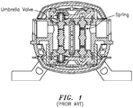
- Figure 1 shows a diaphragm pump having a pump manifold with springloaded or 'umbrella' valves, which is known in the art.
- the spring is arranged between upper and lower umbrella valves.
- Pump are also known in the art having fixed wiring. Shortcomings of the known diaphragm pump configurations may include one or more of the following:
- the present invention relates to a dual diaphragm pump as claimed in claim 1.
- the present invention may include one or more of the following features:
- the at least one inlet port may include dual inlet ports configured to receive inlet port fitting connections, and the at least one outlet port may include dual outlet ports configured to receive outlet port fitting connections.
- the inlet duckbill check valve assembly may include two duckbill check valves, and the outlet duckbill check valve assembly comprises two duckbill check valves.
- the manifold assembly may include two manifold assembly covers or plates attached to upper and lower surfaces of the manifold body and configured with the first and second upper and lower manifold conduits for providing fluid from the inlet check valve assembly channel to the outlet check valve assembly channel.
- the manifold body may include, or take the form of, a plastic injection molded integral structure.
- the dual inlet ports may be configured or oriented orthogonal to one another; and the dual outlet ports are configured or oriented orthogonal to one another.
- the dual inlet ports and the inlet chamber may be configured to receive the fluid from two fluid sources for mixing together in the inlet chamber; and the dual outlet ports and the outlet chamber may be configured to provide a mixed fluid to the at least one fluid outlet source, including where the at least one fluid outlet source includes two fluid outlet sources.
- the inlet duckbill check valve assembly and the outlet duckbill check valve assembly may be configured to process a particle medium having up to 4 millimeters (mm) in diameter.
- Either the dual inlet ports, or the dual outlet ports, or both the dual inlet ports and the dual outlet ports may be configured to receive different port fitting connections, including where the different port fitting connections include a port fitting connection that allows the passage of the fluid either to or from the respective port, and a corresponding port fitting connection that does not allow the passage of the fluid either to or from the respective port.
- the pump having the aforementioned diaphragm pumping and manifold assemblies according to the present invention solves problems that have plagued the prior art pump shown in Figure 1 , and provides an important contribution to the state of the art.
- Figures 2-8 show a dual diaphragm pump generally indicated as 10, according to some embodiments of the present invention.
- Figures 1-5 show the dual diaphragm pump generally indicated as 10 having a single inlet/outlet configuration.
- Figures 6-8 show configurations for a dual diaphragm pump having a multiple inlet/outlet configuration.
- the dual diaphragm pump may be configured with a multipart pump housing, e.g., having a motor housing 11a and a removable front cover 11b, and may also include a pump stand or mount 11c.
- Figure 2A shows a motor 13 and a motor shaft/diaphragm actuator assembly 15 arranged in the multipart pump housing, which couples to upper and lower diaphragm pumping assemblies generally indicated as 12, 14 (see Figures 7A , 7B and 7C ), e.g., that cooperate consistent with that described below.
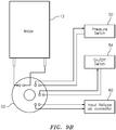
- Figures 7A , 7B, 7C also shows the dual diaphragm pump configured with a pressure sensor or switch module 50 (see also Fig. 9B ) that senses the pressure of the fluid being pumped, and provides a suitable pressure sensing signal containing information about the pressure sensed.
- Pressure sensors and/or switches are known in the art, and the scope of the invention is not intended to be limited to any particular type or kind thereof either now known or later developed in the future.
- FIGS 7A , 7B and 7C the front pump housing for covering the configuration of the multiport manifold assembly is not shown, e.g., which is analogous to element 11b in Figures 1-5 .
- the scope of the invention is not intended to be limited to how the multipart pump housing may be configured, combined or assembled together, etc., e.g., including the number of discrete parts in the configuration, combination or assembly.
- Figures 2 through 4A and 8 show that the dual diaphragm pump may also be configured with a quick connector 60 (see also Fig. 9B ) for coupling to a corresponding connector for providing electrical power to the pump, e.g., including from a wall mounted transformer (not shown).
- the quick connector 60 configured on the pump wiring allows a user to specify the connector they require, and the wiring from their system would be configured with a suitable mating connector and plug for coupling directly into the pump.
- This quick connector configuration 60 allows for a quick and safe removal of a pump for a power source for the purpose of servicing.
- Flexible wiring options may also be configured that also allow for remote mounting of signal input/output devices and a power input.
- the diaphragm pump may include a manifold assembly like elements 20 and 20', e.g., as shown in Figures 6 and 7 .
- Figure 7 shows the manifold assembly 20 equipped with internal input and output duckbill valves 30, 32, 40, 42 that allow for the passing of solids and particulate in the liquid being pumped without fouling or clogging the internal duckbill valves 30, 32, 40, 42.
- the integration of the internal duckbill valves 30, 32, 40, 42 allows the diaphragm pump 10 to handle higher viscosity fluids with less restriction and is capable of passing a larger particle medium of sizes up to 4 millimeters (mm) in diameter, especially when compared to the prior art pump shown in Figure 1 .
- the internal input and output duckbill valves 30, 32, 40, 42 can be reinforced with an internal support to prevent the respective valve from collapsing in applications that will generate higher back pressures during operation or when the pump is not running, e.g., consistent with that disclosed in Patent No. US 8,276,616 and US 8,690,554 , which are assigned to the assignee of the present application.
- the diaphragm pump may include the upper and lower diaphragm pumping assemblies generally indicated as 12, 14 in combination with the manifold assembly 20, e.g., as shown in Figure 4A and 5 .
- the upper and lower diaphragm pumping assemblies 12, 14 may be configured with upper and lower diaphragm 12a, 14a, and upper and lower diaphragm assembly covers or plates 12b, 14b that are respectively fastened to the manifold assembly 20, as shown. See the five (5) fasteners/screws like element f1 in Figures 7A , 7B and 7C , and the corresponding five (5) fastener openings like element o1 configured or formed in the manifold assembly 20 in Figure 7 . See also Figures 7A , 7B and 7C , which show the upper diaphragm pumping assembly 12.
- the upper and lower diaphragm pumping assemblies 12, 14 may be configured for pumping fluid through the dual diaphragm pump 10.
- the upper diaphragm pumping assembly 12 may be configured to draw the fluid from the inlet chamber 20a into the manifold assembly 20, through the upper input duckbill valve 30, through the upper output duckbill valve 40, to the outlet chamber 20b and from the manifold assembly 20; and the lower diaphragm pumping assembly 14 may be configured to draw the fluid from the inlet chamber 20a into the manifold assembly 20, through the lower input duckbill valve 32, through the lower output duckbill valve 42, to the outlet chamber 20b and from the manifold assembly 20, e.g., consistent with that shown in Figure 5 .
- the manifold assembly 20 may be configured or arranged between the upper and lower diaphragm pumping assemblies 12, 14 and have components configured to operate as follows: As best shown in Figures 5 and 7 , in addition to the inlet chamber 20a, and the outlet chamber 20b, the manifold assembly 20 may also include or be configured with a combination of a one-piece integral manifold body 20c, an inlet check valve assembly channel 20d having upper diaphragm pumping assembly orifices, one such inlet orifice which is labeled 20d(1), and an outlet check valve assembly channel 20e having upper and lower diaphragm pumping assembly orifices, one such outlet orifice which is labeled 20e(1).
- the inlet 20a may be configured with dual inlet ports generally indicated as 20a(1), 20a(2) to receive the fluid from at least one fluid source (not shown).
- the dual inlet ports 20a(1), 20a(2) may be configured with inlet port channels 20a(3), 20a(4) to slidably receive inlet fitting couplers 20a(5), 20a(6) that couple inlet fittings 20a(7), 20a(8) to the dual inlet ports 20a(1), 20a(2) of the manifold assembly 20.
- the inlet check valve assembly channel 20d may include an inlet duckbill check valve assembly arranged therein that may include the inlet duckbill check valve 30, 32, as well as one or more other inlet duckbill check valve assembly components like valve receiving members 30(1), 32(1), and internal supports (not shown) to prevent the valve from collapsing in applications that will generate higher back pressures during operation or when the pump is not running, e.g., consistent with that disclosed in Patent No. US 8,276,616 and US 8,690,554 .
- the manifold body 20c may include, or take the form of, a plastic injection molded integral structure, although embodiments are envisioned using other structures or configuration falling within the scope of the appended claims.
- Figure 5 shows a flowpath of fluid through the dual diaphragm pump, including an input partway of a fluid flow path FP in for fluid flowing into the inlet 20a, an internal part for fluid flowing through the inlet check valve assembly channel 20d, through the upper and lower diaphragm pumping assemblies 12, 14, and through the outlet check valve assembly channel 20e, and an output flowpath FP out for fluid flowing from the outlet 20b, e.g., consistent with that set forth herein.
- the upper diaphragm pumping assembly inlet orifice 20d(1) may be configured to be in fluidic communication with the upper diaphragm pumping assembly like element 12 arranged therein to receive the fluid from the inlet duckbill check valve 30, as well as one or more other inlet duckbill check valve assembly components like valve receiving members 30(1), provide (i.e. pump) the fluid via upper manifold conduits indicated by reference label 12b', 12b", 12"', to the upper diaphragm pumping assembly orifice 20e(1).
- the motor shaft/diaphragm actuator assembly 15 together with the diaphragm 12a may be configured in order to provide the liquid from the upper manifold conduit 12b', through the upper manifold conduits 12b", and to the upper manifold conduit 12"'.
- the upper diaphragm pumping assembly outlet orifice 20e(1) may be configured to be in fluidic communication with the outlet check valve assembly channel 20e, for providing fluid to the outlet duckbill check valve 40, as well as one or more other outlet duckbill check valve assembly components like valve receiving members 40(1), and provide (i.e. pump) the fluid to the outlet 20b.
- the lower diaphragm pumping assembly 14 is configured to operate in a similar manner to the upper diaphragm pumping assembly 12.
- the outlet 20b may be configured with dual outlet ports generally indicated as 20b(1), 20b(2) to provide the fluid the pump 10 to at least one fluid outlet source (not shown).
- the dual outlet ports 20b(1), 20b(2) may be configured with outlet port channels 20b(3), 20b(4) to slidably receive outlet fitting couplers 20b(5), 20b(6) that couple outlet fittings 20b(7), 20b(8) to the dual outlet ports 20b(1), 20b(2) of the manifold assembly 20.
- Figures 7, 7A , 7B and 7C show multi-directional port configurations.
- the present invention allows for many different inlet/outlet port connections which provide for flexibility in certain tight, fixed spaces.
- mixing of two (2) different fluids may be made possible as well; and the dual discharge ports allow for two (2) dispensing valves/faucets.
- the dual inlet ports 20a(1), 20a(2) may be configured or oriented orthogonal to one another; and the dual outlet ports 20b(1), 20b(2) are configured or oriented orthogonal to one another, although embodiments are envisioned using other types or kinds of geometric relationship between the dual inlet ports, the dual output ports, or both.
- the dual inlet ports 20a(1), 20a(2) and the inlet chamber 20a may be configured to receive the fluid from two fluid sources (not shown) for mixing together in the inlet chamber 20a; and the dual outlet ports 20b(1), 20b(2) and the outlet chamber 20b are configured to provide a mixed fluid to at least one fluid outlet source (not shown).
- the inlet duckbill check valve assembly 20d and the outlet duckbill check valve assembly 20e may be configured to process a particle medium having up to 4 millimeters (mm) in diameter.
- Either the dual inlet ports 20a(1), 20a(2), or the dual outlet ports 20b(1), 20b(2), or both the dual inlet ports 20a(1), 20a(2) and the dual outlet ports 20b(1), 20b(2), may be configured to receive different port fitting connections.
- Figure 6 shows an alternative embodiment of the manifold assembly 20', having parts and components thereof labeled similar to the parts and components of the manifold assembly 20 in Figure 7 with the additional of a single quote " ' ".
- the manifold assembly 20' is configured to operate in a manner substantially similar to the manifold assembly 20 ( Figure 7 ).
- Figure 9A shows a flowchart generally indicated as 100 having steps 100a through 100k for implementing control functionality according to the present invention for operating a pump, e.g., having at least some combination of the components shown in Figure 9B , consistent with that set forth herein.
- the electronics controller may include, or take the form of, an electronic PCBA 52, e.g., that may be internal to the pump, as shown in Fig. 9B .
- Food and Beverage dispensing/processing Fluid and chemical transfer and mixing, any application that may require moving liquid with high viscosity, particulates and/or solids.
Landscapes
- Engineering & Computer Science (AREA)
- Mechanical Engineering (AREA)
- General Engineering & Computer Science (AREA)
- Reciprocating Pumps (AREA)
- Details Of Reciprocating Pumps (AREA)
Description
- The present invention relates to a pump for providing fluid and particulate; and more particularly relates to a diaphragm pump having a manifold assembly for pumping viscous fluid having solids and particulates. Features related to the subject-matter of
claim 1 are known fromEP 1 437 178 A2 -
Figure 1 shows a diaphragm pump having a pump manifold with springloaded or 'umbrella' valves, which is known in the art. InFigure 1 , the spring is arranged between upper and lower umbrella valves. Pump are also known in the art having fixed wiring. Shortcomings of the known diaphragm pump configurations may include one or more of the following: - a. Valve Types - Spring loaded and umbrella style valves are limited to pumping low viscosity and "debris free" fluids. Liquids with high viscosity and/or particulates cause priming and performance issues on existing valve types.
- i. Umbrella type valves - Consistent with that shown in
Figure 1 , these umbrella type valves typically easily clog due to particulates in the fluid.
When the umbrella type valves are clogged/fouled, they will not seal properly and this prevents the pump from priming and building pressure. - ii. Spring loaded valves - Consistent with that shown in
Figure 1 , the solids in the liquid being pumped typically become entangled in the spring mechanism and prevent the valve from opening and closing.
- i. Umbrella type valves - Consistent with that shown in
- b. Pumps having fixed wiring do not have the flexibility to quick connect/disconnect for servicing. Typical pumps have fixed wiring extending from the motor. If the user requires a connector that must be attached to the existing wires.
- c. Most pumps in the marketplace today usually have 1 inlet and 1 discharge ports from the left and right side of pump head. Therefore, they are limited to only 1 way of connecting the inlet/outlet fittings.
- In view of this, there is a need in the industry for a pump that solves these shortcomings in the pumps that are known in art.
- The present invention relates to a dual diaphragm pump as claimed in
claim 1. - The present invention may include one or more of the following features:
The at least one inlet port may include dual inlet ports configured to receive inlet port fitting connections, and the at least one outlet port may include dual outlet ports configured to receive outlet port fitting connections. - The inlet duckbill check valve assembly may include two duckbill check valves, and the outlet duckbill check valve assembly comprises two duckbill check valves.
- The manifold assembly may include two manifold assembly covers or plates attached to upper and lower surfaces of the manifold body and configured with the first and second upper and lower manifold conduits for providing fluid from the inlet check valve assembly channel to the outlet check valve assembly channel.
- The manifold body may include, or take the form of, a plastic injection molded integral structure.
- The dual inlet ports may be configured or oriented orthogonal to one another; and the dual outlet ports are configured or oriented orthogonal to one another.
- The dual inlet ports and the inlet chamber may be configured to receive the fluid from two fluid sources for mixing together in the inlet chamber; and the dual outlet ports and the outlet chamber may be configured to provide a mixed fluid to the at least one fluid outlet source, including where the at least one fluid outlet source includes two fluid outlet sources.
- The inlet duckbill check valve assembly and the outlet duckbill check valve assembly may be configured to process a particle medium having up to 4 millimeters (mm) in diameter.
- Either the dual inlet ports, or the dual outlet ports, or both the dual inlet ports and the dual outlet ports, may be configured to receive different port fitting connections, including where the different port fitting connections include a port fitting connection that allows the passage of the fluid either to or from the respective port, and a corresponding port fitting connection that does not allow the passage of the fluid either to or from the respective port.
- Advantages of the present invention may include one or more of the following:
- a. Capability to pump high viscosity fluids.
- b. Capable of handling solids and particulates in the fluid being pumped.
- c. Reinforced duckbills prevent the check valve from collapsing during operations that generate higher back pressures.
- d. Flexible wiring options for quick connect/disconnect for servicing allowing easier installation, servicing and general maintenance.
- e. Multiple port pump housing or assembly that allows for flexibility of port fitting connections and dispensing/mixing.
- In effect, the pump having the aforementioned diaphragm pumping and manifold assemblies according to the present invention solves problems that have plagued the prior art pump shown in
Figure 1 , and provides an important contribution to the state of the art. - The drawing, which are not necessarily drawn to scale, includes the following Figures:
-
Figure 1 shows a front-to-back cross-sectional view of a pump that is known in the art. -
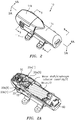
Figure 2 shows a perspective view of a pump having a single inlet and outlet, according to some embodiments of the present invention. -
Figure 2A shows a cross-sectional view of a lower half of the pump inFigure 2 along lines andarrows 2A-2A, according to some embodiments of the present invention. -
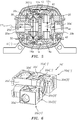
Figure 3 shows a top down plan view of the pump inFigure 2 , according to some embodiments of the present invention. -
Figure 4 shows a side view of the pump inFigure 2 , according to some embodiments of the present invention. -
Figure 4A shows a cross-sectional view of a left side of the pump inFigure 2 along lines andarrows 4A-4A, according to some embodiments of the present invention. -
Figure 5 shows a front-to-back cross-sectional view of the pump inFigure 2 along lines and arrows 5-5, according to some embodiments of the present invention. -
Figure 6 shows a top perspective view of a pump housing with multi-ports, including inlet ports and outlet ports, according to some embodiments of the present invention. -
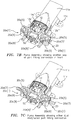
Figure 7 shows a top perspective view of a pump housing with multi-ports including inlet ports and outlet ports, according to other embodiments of the present invention. -
Figure 7(A) shows a top perspective view of part of a pump having a pump assembly with the pump housing inFigure 7 configured with inlet/outlet port fitting connections extending in left/right directions transverse to the longitudinal axis of the pump, according to other embodiments of the present invention. -
Figure 7(B) shows a top perspective view of part of a pump having a pump assembly with the pump housing inFigure 7 configured with inlet/outlet port fitting connections extending in a front direction along the longitudinal axis of the pump, according to other embodiments of the present invention. -
Figure 7(C) shows a top perspective view of part of a pump having a pump assembly with the pump housing inFigure 7 configured with inlet/outlet port fitting connections extending in the left/right directions and a dual outlet port fitting connection extending in a left/right direction and a front direction, according to other embodiments of the present invention. -
Figure 8 shows a back-to-front cross-sectional view of the pump inFigure 2 along lines and arrows 8-8, according to some embodiments of the present invention. -
Figure 9A shows a flowchart having steps for implementing control functionality for operating a pump arrangement or configuration like that shown inFigure 9B , according to some embodiments of the present invention. -
Figure 9B shows part of a pump arrangement or configuration having a motor coupled via a printed circuit board assembly (PCBA) to a pressure switch, an on/off switch and a connector for receiving an input, for operating a pump, according to some embodiments of the present invention. -
Figures 2-8 show a dual diaphragm pump generally indicated as 10, according to some embodiments of the present invention.Figures 1-5 show the dual diaphragm pump generally indicated as 10 having a single inlet/outlet configuration. In contrast,Figures 6-8 show configurations for a dual diaphragm pump having a multiple inlet/outlet configuration. In either case, the dual diaphragm pump may be configured with a multipart pump housing, e.g., having amotor housing 11a and a removablefront cover 11b, and may also include a pump stand or mount 11c.Figure 2A shows amotor 13 and a motor shaft/diaphragm actuator assembly 15 arranged in the multipart pump housing, which couples to upper and lower diaphragm pumping assemblies generally indicated as 12, 14 (seeFigures 7A ,7B and 7C ), e.g., that cooperate consistent with that described below.Figures 7A ,7B, 7C also shows the dual diaphragm pump configured with a pressure sensor or switch module 50 (see alsoFig. 9B ) that senses the pressure of the fluid being pumped, and provides a suitable pressure sensing signal containing information about the pressure sensed. Pressure sensors and/or switches are known in the art, and the scope of the invention is not intended to be limited to any particular type or kind thereof either now known or later developed in the future. InFigures 7A ,7B and 7C , the front pump housing for covering the configuration of the multiport manifold assembly is not shown, e.g., which is analogous toelement 11b inFigures 1-5 . The scope of the invention is not intended to be limited to how the multipart pump housing may be configured, combined or assembled together, etc., e.g., including the number of discrete parts in the configuration, combination or assembly. - Moreover,
Figures 2 through 4A and8 show that the dual diaphragm pump may also be configured with a quick connector 60 (see alsoFig. 9B ) for coupling to a corresponding connector for providing electrical power to the pump, e.g., including from a wall mounted transformer (not shown). Thequick connector 60 configured on the pump wiring allows a user to specify the connector they require, and the wiring from their system would be configured with a suitable mating connector and plug for coupling directly into the pump. Thisquick connector configuration 60 allows for a quick and safe removal of a pump for a power source for the purpose of servicing. Flexible wiring options may also be configured that also allow for remote mounting of signal input/output devices and a power input. - The diaphragm pump may include a manifold assembly like
elements 20 and 20', e.g., as shown inFigures 6 and7 . - By way of example,
Figure 7 shows themanifold assembly 20 equipped with internal input andoutput duckbill valves internal duckbill valves internal duckbill valves diaphragm pump 10 to handle higher viscosity fluids with less restriction and is capable of passing a larger particle medium of sizes up to 4 millimeters (mm) in diameter, especially when compared to the prior art pump shown inFigure 1 . The internal input andoutput duckbill valves US 8,276,616 andUS 8,690,554 , which are assigned to the assignee of the present application. - The diaphragm pump may include the upper and lower diaphragm pumping assemblies generally indicated as 12, 14 in combination with the
manifold assembly 20, e.g., as shown inFigure 4A and5 . By way of example, the upper and lowerdiaphragm pumping assemblies lower diaphragm plates manifold assembly 20, as shown. See the five (5) fasteners/screws like element f1 inFigures 7A ,7B and 7C , and the corresponding five (5) fastener openings like element o1 configured or formed in themanifold assembly 20 inFigure 7 . See alsoFigures 7A ,7B and 7C , which show the upperdiaphragm pumping assembly 12. - In operation, the upper and lower
diaphragm pumping assemblies dual diaphragm pump 10. By way of example, the upperdiaphragm pumping assembly 12 may be configured to draw the fluid from theinlet chamber 20a into themanifold assembly 20, through the upperinput duckbill valve 30, through the upperoutput duckbill valve 40, to theoutlet chamber 20b and from themanifold assembly 20; and the lowerdiaphragm pumping assembly 14 may be configured to draw the fluid from theinlet chamber 20a into themanifold assembly 20, through the lowerinput duckbill valve 32, through the loweroutput duckbill valve 42, to theoutlet chamber 20b and from themanifold assembly 20, e.g., consistent with that shown inFigure 5 . - The
manifold assembly 20 may be configured or arranged between the upper and lowerdiaphragm pumping assemblies
As best shown inFigures 5 and7 , in addition to theinlet chamber 20a, and theoutlet chamber 20b, themanifold assembly 20 may also include or be configured with a combination of a one-piece integralmanifold body 20c, an inlet checkvalve assembly channel 20d having upper diaphragm pumping assembly orifices, one such inlet orifice which is labeled 20d(1), and an outlet checkvalve assembly channel 20e having upper and lower diaphragm pumping assembly orifices, one such outlet orifice which is labeled 20e(1). - The
inlet 20a may be configured with dual inlet ports generally indicated as 20a(1), 20a(2) to receive the fluid from at least one fluid source (not shown). Thedual inlet ports 20a(1), 20a(2) may be configured withinlet port channels 20a(3), 20a(4) to slidably receive inletfitting couplers 20a(5), 20a(6) thatcouple inlet fittings 20a(7), 20a(8) to thedual inlet ports 20a(1), 20a(2) of themanifold assembly 20. - The inlet check
valve assembly channel 20d may include an inlet duckbill check valve assembly arranged therein that may include the inletduckbill check valve Patent No. US 8,276,616 andUS 8,690,554 . - By way of example, the
manifold body 20c may include, or take the form of, a plastic injection molded integral structure, although embodiments are envisioned using other structures or configuration falling within the scope of the appended claims. -
Figure 5 shows a flowpath of fluid through the dual diaphragm pump, including an input partway of a fluid flow path FPin for fluid flowing into theinlet 20a, an internal part for fluid flowing through the inlet checkvalve assembly channel 20d, through the upper and lowerdiaphragm pumping assemblies valve assembly channel 20e, and an output flowpath FPout for fluid flowing from theoutlet 20b, e.g., consistent with that set forth herein. - The upper diaphragm pumping
assembly inlet orifice 20d(1) may be configured to be in fluidic communication with the upper diaphragm pumping assembly likeelement 12 arranged therein to receive the fluid from the inletduckbill check valve 30, as well as one or more other inlet duckbill check valve assembly components like valve receiving members 30(1), provide (i.e. pump) the fluid via upper manifold conduits indicated byreference label 12b', 12b", 12"', to the upper diaphragm pumpingassembly orifice 20e(1). In operation, and as a person skilled in the art would appreciate, the motor shaft/diaphragm actuator assembly 15 together with thediaphragm 12a may be configured in order to provide the liquid from theupper manifold conduit 12b', through theupper manifold conduits 12b", and to theupper manifold conduit 12"'. The upper diaphragm pumpingassembly outlet orifice 20e(1) may be configured to be in fluidic communication with the outlet checkvalve assembly channel 20e, for providing fluid to the outletduckbill check valve 40, as well as one or more other outlet duckbill check valve assembly components like valve receiving members 40(1), and provide (i.e. pump) the fluid to theoutlet 20b. - As a person skilled in the art would appreciate, the lower
diaphragm pumping assembly 14 is configured to operate in a similar manner to the upperdiaphragm pumping assembly 12. - The
outlet 20b may be configured with dual outlet ports generally indicated as 20b(1), 20b(2) to provide the fluid thepump 10 to at least one fluid outlet source (not shown). Thedual outlet ports 20b(1), 20b(2) may be configured withoutlet port channels 20b(3), 20b(4) to slidably receive outletfitting couplers 20b(5), 20b(6) thatcouple outlet fittings 20b(7), 20b(8) to thedual outlet ports 20b(1), 20b(2) of themanifold assembly 20. -
Figures 7, 7A ,7B and 7C show multi-directional port configurations. In effect, the present invention allows for many different inlet/outlet port connections which provide for flexibility in certain tight, fixed spaces. By way of example, with the dual inlet ports, mixing of two (2) different fluids may be made possible as well; and the dual discharge ports allow for two (2) dispensing valves/faucets. - As shown, the
dual inlet ports 20a(1), 20a(2) may be configured or oriented orthogonal to one another; and thedual outlet ports 20b(1), 20b(2) are configured or oriented orthogonal to one another, although embodiments are envisioned using other types or kinds of geometric relationship between the dual inlet ports, the dual output ports, or both. - The
dual inlet ports 20a(1), 20a(2) and theinlet chamber 20a may be configured to receive the fluid from two fluid sources (not shown) for mixing together in theinlet chamber 20a; and thedual outlet ports 20b(1), 20b(2) and theoutlet chamber 20b are configured to provide a mixed fluid to at least one fluid outlet source (not shown). - The inlet duckbill
check valve assembly 20d and the outlet duckbillcheck valve assembly 20e may be configured to process a particle medium having up to 4 millimeters (mm) in diameter. - Either the
dual inlet ports 20a(1), 20a(2), or thedual outlet ports 20b(1), 20b(2), or both thedual inlet ports 20a(1), 20a(2) and thedual outlet ports 20b(1), 20b(2), may be configured to receive different port fitting connections. - It is noted that in
Figures 7A ,7B and 7C the part of the pump shown does not include, by way of example, the front pump housing analogous toelement 11b inFigure 2 . A person skilled in the art would appreciate how to configured such a front pump housing without undue experimentation, e.g., based on that disclosed herein. -
Figure 6 shows an alternative embodiment of the manifold assembly 20', having parts and components thereof labeled similar to the parts and components of themanifold assembly 20 inFigure 7 with the additional of a single quote " ' ". The manifold assembly 20' is configured to operate in a manner substantially similar to the manifold assembly 20 (Figure 7 ). -
Figure 9A shows a flowchart generally indicated as 100 havingsteps 100a through 100k for implementing control functionality according to the present invention for operating a pump, e.g., having at least some combination of the components shown inFigure 9B , consistent with that set forth herein. - Controller 52 - The electronics controller may include, or take the form of, an
electronic PCBA 52, e.g., that may be internal to the pump, as shown inFig. 9B . - i.
Steps integral connector 60, which allows for direct power to the pump via the end user's source or from a wall mount transformer (not shown), so the On/Off switch 54 can be turned On. - ii.
Steps control circuit 52 then applies power to themotor 13 and allows a pre-designated time for priming. If the pump exceeds that time and there is a low/no current draw condition, then thecontrol circuit 52 shuts the power off. Thecontrol circuit 52 then sends a signal indicating that the pump has shut down due to a run dry/no power condition. By way of example, the signal may take the form of an audio or visual alarm, as well as a wireless signal provided to a remote location, including a wifi signal transferred via the Internet to a remote (e.g., off site) access point. - iii.
Steps control circuit 52 monitors the current draw on the pump, and if the pump unit's current draw drops beneath a designated current range, whether by the fluid being pumped being exhausted or by some other issue, then thecontrol circuit 52 will remove power to themotor 13. Thecontrol circuit 52 then sends a signal indicating that the pump has shut down due to a run dry/no power condition or an out-of-product being dispensed condition. - iv.
Steps control circuit 52 will remove power to themotor 13 and then sends a signal indicating that the pump has shut down due to an over-current condition. - v. By way of further example, if the power to the
circuit board 52 should be removed by thepressure switch 50, e.g., due to an outlet (not shown) being shut off, then thecontrol circuit 52 may be configured to remove power form the pump until the pressure is relieved at which time thecontrol circuit 52 may be configured to automatically turn the pump back on and supply fluid. - vi. By way of further example, if the pump runs continuously for a specified period of time, then the
circuit board 52 may be configured to remove the power from the motor and sends a signal indicating the pump has shut down due to a continuous running or time-out condition. - vii. By way of further example, the
control circuit 52 may also be configured to precisely control the dispense amount and flow rate, e.g., by controlling the time and/or varying the voltage to themotor 13 using a pulse wave modulation (PWM) technique, or other method of motor speed control, including techniques both known in the art or later developed in the future. - viii. By way of further example, the
control circuit 52 may also be used for storing, communicating, and/or remotely adjusting the pump operating parameters/settings, pump performance profiles with various fluids and media, error codes, flow rate, and dispensed quantity information, power consumption, etc. - Food and Beverage dispensing/processing, Fluid and chemical transfer and mixing, any application that may require moving liquid with high viscosity, particulates and/or solids.
Claims (7)
- A dual diaphragm pump (10), comprising:upper and lower diaphragm pumping assemblies (12, 14); anda manifold assembly (20) arranged between the upper andlower diaphragm pumping assemblies (12, 14), the upper and lower diaphragm pumping assemblies (12, 14) configured to pump a particle medium having solids andparticulates with up to four millimeters in diameter through the manifold assembly (20) without fouling orclogging, the manifold assembly (20) having a manifold body that is a plastic injection molded integral structure and includes:an inlet having at least one inlet port (20a(1), 20a(2)) and an inlet chamber (20a) configured to receive the particle medium from at least one fluid source,an inlet check valve assembly channel formed therein and being in fluidic communication with the inlet chamber (20a) and both of the upper and lower diaphragm pumping assemblies (12, 14),an inlet duckbill check valve assembly having two input duckbill check valves (30, 32) arranged in the inlet check valve assembly channel (20d), each input duckbill check valve configured to allow the particle medium to pass from the inlet chamber (20a), through the inlet check valve assembly channel (20d), to a respective one of the upper and lower diaphragm pumping assemblies (12, 14),an outlet check valve assembly channel formed therein and being in fluidic communication with both of the upper and lower diaphragm pumping assemblies (12, 14),an outlet duckbill check valve assembly having two output duckbill check valves (40, 42) arranged in the outlet check valve assembly channel (20e), each output duckbill check valve configured to allow the particle medium to pass from the respective one of the upper and lower diaphragm pumping assemblies (12, 14) and through the outlet check valve assembly channel, andan outlet having an outlet chamber (20b) and at least one outlet port (20b(1), 20b(2)), the outlet chamber (20b) being in fluidic communication with the outlet check valve assembly channel (20e), and configured to allow the particle medium to pass from the outlet check valve assembly channel (20e), through the outlet chamber (20b), to the at least one outlet port (20b(1), 20b(2)) for providing to at least one fluid outlet source.
- A dual diaphragm pump (10) according to claim 1, wherein the at least one inlet port (20a(1), 20a(2)) comprises dual inlet ports (20a(1), 20a(2)) configured to receive inlet port fitting connections, and the at least one outlet port comprises dual outlet ports (20b(1), 20b(2)) configured to receive outlet port fitting connections.
- A dual diaphragm pump (10) according to claim 2, wherein the dual inlet ports (20a(1), 20a(2)) are configured or oriented orthogonal to one another; and the dual outlet ports (20b(1), 20b(2)) are configured or oriented orthogonal to one another.
- A dual diaphragm pump (10) according to claim 2, wherein the dual inlet ports (20a(1), 20a(2)) and the inlet chamber (20a) are configured to receive the particle medium from two fluid sources for mixing together in the inlet chamber (20a); and the dual outlet ports (20b(1), 20b(2)) and the outlet chamber (20b) are configured to provide a mixed fluid to the at least one fluid outlet source.
- A dual diaphragm pump (10) according to claim 2, wherein either the dual inlet ports (20a(1), 20a(2)), or the dual outlet ports (20b(1), 20b(2)), or both the dual inlet ports (20a(1), 20a(2)) and the dual outlet ports (20b(1), 20b(2)) are configured to receive different port fitting connections.
- A dual diaphragm pump (10) according to claim 1, wherein the manifold assembly (20) comprises two manifold assembly plates (12b, 14b) attached to upper and lower surfaces of the manifold body and configured with the first and second upper and lower manifold conduits.
- A dual diaphragm pump (10) according to claim 1, wherein the two input duckbill check valves (30, 32) include an upper input duckbill check valve configured to provide the particle medium from the inlet check valve assembly channel (20d) to an upper diaphragm pumping assembly, and include a lower input duckbill check valve configured to provide the particle medium from the inlet check valve assembly channel (20d) to a lower diaphragm pumping assembly; and
the two output duckbill check valves (40, 42) include an upper output duckbill check valve configured to provide the particle medium from an upper diaphragm pumping assembly via the outlet check valve assembly channel (20e) to the outlet chamber (20b), and include a lower output duckbill check valve configured to provide the particle medium from a lower diaphragm pumping assembly via the outlet check valve assembly channel (20e) to the outlet chamber (20b).
Applications Claiming Priority (2)
| Application Number | Priority Date | Filing Date | Title |
|---|---|---|---|
| US201462012526P | 2014-06-16 | 2014-06-16 | |
| PCT/US2015/035968 WO2015195624A1 (en) | 2014-06-16 | 2015-06-16 | Diaphragm pump utilizing duckbill valves, multi-directional ports and flexible electrical connectivity |
Publications (3)
| Publication Number | Publication Date |
|---|---|
| EP3155263A1 EP3155263A1 (en) | 2017-04-19 |
| EP3155263A4 EP3155263A4 (en) | 2018-01-24 |
| EP3155263B1 true EP3155263B1 (en) | 2021-03-17 |
Family
ID=54936030
Family Applications (1)
| Application Number | Title | Priority Date | Filing Date |
|---|---|---|---|
| EP15808975.5A Active EP3155263B1 (en) | 2014-06-16 | 2015-06-16 | Diaphragm pump utilizing duckbill valves, multi-directional ports and flexible electrical connectivity |
Country Status (10)
| Country | Link |
|---|---|
| US (2) | US20160017882A1 (en) |
| EP (1) | EP3155263B1 (en) |
| JP (1) | JP6813482B2 (en) |
| CN (1) | CN106662096B (en) |
| AU (2) | AU2015277372A1 (en) |
| CA (1) | CA2952616C (en) |
| ES (1) | ES2873199T3 (en) |
| MX (1) | MX389902B (en) |
| RU (1) | RU2717036C2 (en) |
| WO (1) | WO2015195624A1 (en) |
Families Citing this family (4)
| Publication number | Priority date | Publication date | Assignee | Title |
|---|---|---|---|---|
| US20170095757A1 (en) | 2015-05-27 | 2017-04-06 | Flow Control LLC | Cartridge Accumulator |
| JP6946195B2 (en) | 2015-05-27 | 2021-10-06 | フロー コントロール リミティド ライアビリティ カンパニー | Cartridge pump |
| EP3857077A4 (en) * | 2018-09-25 | 2022-05-25 | Sun Automation, Inc. | ELECTRICALLY POWERED DIAPHRAGM INK PUMP APPARATUS AND METHOD |
| US12544722B2 (en) | 2019-09-06 | 2026-02-10 | Flow Control LLC | Infusion/mixer pump system—pump with integrated gas liquid mixing valve in an enclosure |
Family Cites Families (48)
| Publication number | Priority date | Publication date | Assignee | Title |
|---|---|---|---|---|
| US2221071A (en) * | 1937-05-29 | 1940-11-12 | Bendix Prod Corp | Pump |
| US2764097A (en) * | 1953-03-04 | 1956-09-25 | Lindsay H Browne | Pump |
| US2922854A (en) | 1957-09-16 | 1960-01-26 | Axel L Nielsen | Sump pump control |
| US3775030A (en) * | 1971-12-01 | 1973-11-27 | Wanner Engineering | Diaphragm pump |
| US4478560A (en) * | 1982-09-23 | 1984-10-23 | The Warren Rupp Company | Fluid-operated reciprocating pump |
| US4583920A (en) | 1983-12-28 | 1986-04-22 | M&T Chemicals Inc. | Positive displacement diaphragm pumps employing displacer valves |
| US4605273A (en) | 1984-12-17 | 1986-08-12 | Horton Paul D | Parallel-blade/twist-lock adapter plug |
| JPS6270678A (en) * | 1985-09-20 | 1987-04-01 | Meiji Kikai Seisakusho:Kk | Diaphragm pump |
| US4597721A (en) * | 1985-10-04 | 1986-07-01 | Valco Cincinnati, Inc. | Double acting diaphragm pump with improved disassembly means |
| GB8708417D0 (en) | 1987-04-08 | 1987-05-13 | Eaton Sa Monaco | Electric pump |
| US4936753A (en) * | 1988-06-03 | 1990-06-26 | The Aro Corporation | Diaphragm pump with interchangeable valves and manifolds |
| US5071370A (en) | 1990-12-04 | 1991-12-10 | Metropolitan Pump Company | Connector system for use with electrically operable pumps |
| EP0524820A3 (en) | 1991-07-24 | 1993-10-27 | Binks Bullows Ltd | Diaphragm pump |
| CN2140463Y (en) * | 1992-03-27 | 1993-08-18 | 唐永奎 | Fluid mixer |
| US5332372A (en) * | 1992-04-20 | 1994-07-26 | Warren Rupp, Inc. | Modular double-diaphragm pump |
| US5304073A (en) | 1992-06-05 | 1994-04-19 | Carr-Griff, Inc. | Electrical connector and pump assembly utilizing same |
| US5391060A (en) * | 1993-05-14 | 1995-02-21 | The Aro Corporation | Air operated double diaphragm pump |
| US5368452A (en) * | 1993-07-20 | 1994-11-29 | Graco Inc. | Double diaphragm pump having two-stage air valve actuator |
| RU2068118C1 (en) * | 1993-08-10 | 1996-10-20 | Евгений Анатольевич Каушнян | Fluid-pressure-operated diaphragm pump |
| IL115327A (en) | 1994-10-07 | 2000-08-13 | Bayer Ag | Diaphragm pump |
| GB9423174D0 (en) * | 1994-11-17 | 1995-01-04 | Clarke Peter | Diaphragm pump |
| RU2101567C1 (en) | 1995-10-12 | 1998-01-10 | Научно-производственное объединение "Искра" | Double-action diaphragm pump |
| US5848878A (en) * | 1996-06-21 | 1998-12-15 | Ingersoll-Rand Company | Pump with improved manifold |
| JP4071334B2 (en) * | 1998-01-09 | 2008-04-02 | 本田技研工業株式会社 | Fluid pump |
| US6234823B1 (en) | 1999-03-29 | 2001-05-22 | Paul Martin Fuess | Plug adapter having eccentric ring driving cord retention wedge |
| US6325932B1 (en) | 1999-11-30 | 2001-12-04 | Mykrolis Corporation | Apparatus and method for pumping high viscosity fluid |
| US7156614B2 (en) * | 2000-01-26 | 2007-01-02 | The Gorman-Rupp Company | Centrifugal pump with multiple inlets |
| DE10300280A1 (en) * | 2003-01-08 | 2004-07-22 | Itw Gema Ag | Pump device for powder, process therefor and powder coating device |
| US7390175B2 (en) * | 2004-02-27 | 2008-06-24 | Hypro, Llc | Double action simplex plunger pump |
| US6863574B1 (en) | 2004-04-05 | 2005-03-08 | Johannes Cornelius N. Bosch | Plug assembly |
| US7670479B2 (en) | 2004-05-24 | 2010-03-02 | PUR Water Purification, Inc. | Fluid container having an additive dispensing system |
| US7572114B2 (en) * | 2005-06-21 | 2009-08-11 | Sonic Tractor Parts, Inc. | Structure of pump |
| US20090092507A1 (en) * | 2005-08-05 | 2009-04-09 | Ramirez Jr Emilio A | Fluid pump systems |
| WO2008021503A2 (en) * | 2006-08-18 | 2008-02-21 | L*Vad Technology, Inc. | Air supply mechanism for ventricular assist system |
| US7690342B2 (en) | 2007-01-05 | 2010-04-06 | Walbro Engine Management, L.L.C. | Priming circuit for a fuel system |
| EP2155084B1 (en) | 2007-04-03 | 2013-11-27 | Dfine, Inc. | Bone treatment systems |
| JP5695908B2 (en) * | 2007-12-10 | 2015-04-08 | バイエル メディカル ケア インコーポレーテッド | Continuous fluid transport system and fluid transport method |
| US8151885B2 (en) * | 2009-04-20 | 2012-04-10 | Halliburton Energy Services Inc. | Erosion resistant flow connector |
| US20110081265A1 (en) | 2009-10-06 | 2011-04-07 | Williams Hansford R | Pulse pump |
| US20110139825A1 (en) | 2009-12-10 | 2011-06-16 | Kao Brands Company | Diaphragm-style bottle pump |
| US20110171045A1 (en) * | 2010-01-14 | 2011-07-14 | Briggs & Stratton Corporation | Pressure washer pump |
| JP2012233465A (en) | 2011-05-09 | 2012-11-29 | Ricoh Co Ltd | Fluid transferer, fluid filling apparatus and fluid transfer method |
| US8690554B2 (en) * | 2011-07-15 | 2014-04-08 | Xylem Ip Holdings Llc | Diaphragm pump using duckbill and other types of valves |
| US20130094983A1 (en) | 2011-10-13 | 2013-04-18 | Gojo Industries, Inc. | Diaphragm foam pump for foam dispensers and refill units |
| US20130178826A1 (en) | 2011-11-18 | 2013-07-11 | Minipumps, Llc. | Accurate flow control in drug pump devices |
| US9427505B2 (en) * | 2012-05-15 | 2016-08-30 | Smith & Nephew Plc | Negative pressure wound therapy apparatus |
| CN104619426A (en) * | 2012-09-13 | 2015-05-13 | 格瑞克明尼苏达有限公司 | Accumulator for airless sprayer |
| PL3102829T3 (en) * | 2014-02-07 | 2019-07-31 | Graco Minnesota Inc. | Pulseless positive displacement pump and method of pulselessly displacing fluid |
-
2015
- 2015-06-16 AU AU2015277372A patent/AU2015277372A1/en not_active Abandoned
- 2015-06-16 CA CA2952616A patent/CA2952616C/en active Active
- 2015-06-16 ES ES15808975T patent/ES2873199T3/en active Active
- 2015-06-16 CN CN201580037557.5A patent/CN106662096B/en active Active
- 2015-06-16 WO PCT/US2015/035968 patent/WO2015195624A1/en not_active Ceased
- 2015-06-16 JP JP2017519214A patent/JP6813482B2/en active Active
- 2015-06-16 US US14/740,577 patent/US20160017882A1/en not_active Abandoned
- 2015-06-16 MX MX2016016757A patent/MX389902B/en unknown
- 2015-06-16 RU RU2016149520A patent/RU2717036C2/en active
- 2015-06-16 EP EP15808975.5A patent/EP3155263B1/en active Active
-
2019
- 2019-05-09 AU AU2019203247A patent/AU2019203247B2/en not_active Ceased
-
2020
- 2020-01-21 US US16/748,166 patent/US11898548B2/en active Active
Non-Patent Citations (1)
| Title |
|---|
| None * |
Also Published As
| Publication number | Publication date |
|---|---|
| RU2717036C2 (en) | 2020-03-17 |
| CA2952616C (en) | 2020-11-10 |
| US20160017882A1 (en) | 2016-01-21 |
| WO2015195624A1 (en) | 2015-12-23 |
| AU2015277372A1 (en) | 2017-01-12 |
| US11898548B2 (en) | 2024-02-13 |
| CN106662096B (en) | 2019-07-19 |
| JP2017519158A (en) | 2017-07-13 |
| EP3155263A4 (en) | 2018-01-24 |
| NZ727587A (en) | 2020-12-18 |
| CN106662096A (en) | 2017-05-10 |
| RU2016149520A3 (en) | 2018-11-13 |
| MX2016016757A (en) | 2017-06-26 |
| ES2873199T3 (en) | 2021-11-03 |
| US20200158105A1 (en) | 2020-05-21 |
| AU2019203247B2 (en) | 2021-03-25 |
| MX389902B (en) | 2025-03-20 |
| RU2016149520A (en) | 2018-07-16 |
| CA2952616A1 (en) | 2015-12-23 |
| EP3155263A1 (en) | 2017-04-19 |
| JP6813482B2 (en) | 2021-01-13 |
| AU2019203247A1 (en) | 2019-05-30 |
Similar Documents
| Publication | Publication Date | Title |
|---|---|---|
| US11898548B2 (en) | Diaphragm pump utilizing duckbill valves, multi-directional ports and flexible electrical connectivity | |
| KR101810719B1 (en) | Customizable dispense system with smart controller | |
| US11965496B2 (en) | Dosing pump system | |
| CN104632703B (en) | For heating and/or the circulation pump assembly of cooling system | |
| US6241487B1 (en) | Fluid powered diaphragm pump | |
| RU2009127538A (en) | INSTALLATION FOR FLUID SUPPLY AND RELATED METHODS | |
| WO2007109775A3 (en) | Liquid filtration systems | |
| EP3296447A1 (en) | Distributor and electrical appliance equipped with said distrubutor | |
| NZ727587B2 (en) | Diaphragm pump utilizing duckbill valves, multi-directional ports and flexible electrical connectivity | |
| JP2017519158A5 (en) | ||
| CA2973872A1 (en) | Electronic plumbing fixture fitting with electronic valve including piston and seat | |
| CN114367320A (en) | Micro-droplet preparation device and preparation method thereof | |
| CN215172490U (en) | Electromagnetic valve integrated assembly, structure and electric appliance | |
| CN110630484B (en) | A microfluidic pump control device and a multi-way valve microfluidic pump control system | |
| JP2023537113A (en) | Pump assembly and liquid dispensing device | |
| JPH04293536A (en) | Liquid preparing apparatus | |
| EP3117104A1 (en) | Submersible pump and method of pumping fluid |
Legal Events
| Date | Code | Title | Description |
|---|---|---|---|
| STAA | Information on the status of an ep patent application or granted ep patent |
Free format text: STATUS: THE INTERNATIONAL PUBLICATION HAS BEEN MADE |
|
| PUAI | Public reference made under article 153(3) epc to a published international application that has entered the european phase |
Free format text: ORIGINAL CODE: 0009012 |
|
| STAA | Information on the status of an ep patent application or granted ep patent |
Free format text: STATUS: REQUEST FOR EXAMINATION WAS MADE |
|
| 17P | Request for examination filed |
Effective date: 20161216 |
|
| AK | Designated contracting states |
Kind code of ref document: A1 Designated state(s): AL AT BE BG CH CY CZ DE DK EE ES FI FR GB GR HR HU IE IS IT LI LT LU LV MC MK MT NL NO PL PT RO RS SE SI SK SM TR |
|
| AX | Request for extension of the european patent |
Extension state: BA ME |
|
| DAV | Request for validation of the european patent (deleted) | ||
| DAX | Request for extension of the european patent (deleted) | ||
| A4 | Supplementary search report drawn up and despatched |
Effective date: 20180104 |
|
| RIC1 | Information provided on ipc code assigned before grant |
Ipc: F04B 15/02 20060101ALI20171221BHEP Ipc: F04B 43/02 20060101AFI20171221BHEP Ipc: F04B 43/04 20060101ALI20171221BHEP |
|
| GRAP | Despatch of communication of intention to grant a patent |
Free format text: ORIGINAL CODE: EPIDOSNIGR1 |
|
| STAA | Information on the status of an ep patent application or granted ep patent |
Free format text: STATUS: GRANT OF PATENT IS INTENDED |
|
| RIC1 | Information provided on ipc code assigned before grant |
Ipc: F04B 43/04 20060101ALI20201005BHEP Ipc: F04B 43/02 20060101AFI20201005BHEP Ipc: F04B 15/02 20060101ALI20201005BHEP |
|
| INTG | Intention to grant announced |
Effective date: 20201027 |
|
| GRAS | Grant fee paid |
Free format text: ORIGINAL CODE: EPIDOSNIGR3 |
|
| GRAA | (expected) grant |
Free format text: ORIGINAL CODE: 0009210 |
|
| STAA | Information on the status of an ep patent application or granted ep patent |
Free format text: STATUS: THE PATENT HAS BEEN GRANTED |
|
| AK | Designated contracting states |
Kind code of ref document: B1 Designated state(s): AL AT BE BG CH CY CZ DE DK EE ES FI FR GB GR HR HU IE IS IT LI LT LU LV MC MK MT NL NO PL PT RO RS SE SI SK SM TR |
|
| REG | Reference to a national code |
Ref country code: GB Ref legal event code: FG4D |
|
| REG | Reference to a national code |
Ref country code: CH Ref legal event code: EP |
|
| REG | Reference to a national code |
Ref country code: DE Ref legal event code: R096 Ref document number: 602015067033 Country of ref document: DE |
|
| REG | Reference to a national code |
Ref country code: IE Ref legal event code: FG4D |
|
| REG | Reference to a national code |
Ref country code: AT Ref legal event code: REF Ref document number: 1372482 Country of ref document: AT Kind code of ref document: T Effective date: 20210415 |
|
| REG | Reference to a national code |
Ref country code: LT Ref legal event code: MG9D |
|
| PG25 | Lapsed in a contracting state [announced via postgrant information from national office to epo] |
Ref country code: BG Free format text: LAPSE BECAUSE OF FAILURE TO SUBMIT A TRANSLATION OF THE DESCRIPTION OR TO PAY THE FEE WITHIN THE PRESCRIBED TIME-LIMIT Effective date: 20210617 Ref country code: HR Free format text: LAPSE BECAUSE OF FAILURE TO SUBMIT A TRANSLATION OF THE DESCRIPTION OR TO PAY THE FEE WITHIN THE PRESCRIBED TIME-LIMIT Effective date: 20210317 Ref country code: FI Free format text: LAPSE BECAUSE OF FAILURE TO SUBMIT A TRANSLATION OF THE DESCRIPTION OR TO PAY THE FEE WITHIN THE PRESCRIBED TIME-LIMIT Effective date: 20210317 Ref country code: GR Free format text: LAPSE BECAUSE OF FAILURE TO SUBMIT A TRANSLATION OF THE DESCRIPTION OR TO PAY THE FEE WITHIN THE PRESCRIBED TIME-LIMIT Effective date: 20210618 Ref country code: NO Free format text: LAPSE BECAUSE OF FAILURE TO SUBMIT A TRANSLATION OF THE DESCRIPTION OR TO PAY THE FEE WITHIN THE PRESCRIBED TIME-LIMIT Effective date: 20210617 |
|
| REG | Reference to a national code |
Ref country code: AT Ref legal event code: MK05 Ref document number: 1372482 Country of ref document: AT Kind code of ref document: T Effective date: 20210317 |
|
| REG | Reference to a national code |
Ref country code: NL Ref legal event code: MP Effective date: 20210317 |
|
| PG25 | Lapsed in a contracting state [announced via postgrant information from national office to epo] |
Ref country code: RS Free format text: LAPSE BECAUSE OF FAILURE TO SUBMIT A TRANSLATION OF THE DESCRIPTION OR TO PAY THE FEE WITHIN THE PRESCRIBED TIME-LIMIT Effective date: 20210317 Ref country code: LV Free format text: LAPSE BECAUSE OF FAILURE TO SUBMIT A TRANSLATION OF THE DESCRIPTION OR TO PAY THE FEE WITHIN THE PRESCRIBED TIME-LIMIT Effective date: 20210317 Ref country code: SE Free format text: LAPSE BECAUSE OF FAILURE TO SUBMIT A TRANSLATION OF THE DESCRIPTION OR TO PAY THE FEE WITHIN THE PRESCRIBED TIME-LIMIT Effective date: 20210317 |
|
| PG25 | Lapsed in a contracting state [announced via postgrant information from national office to epo] |
Ref country code: NL Free format text: LAPSE BECAUSE OF FAILURE TO SUBMIT A TRANSLATION OF THE DESCRIPTION OR TO PAY THE FEE WITHIN THE PRESCRIBED TIME-LIMIT Effective date: 20210317 |
|
| PG25 | Lapsed in a contracting state [announced via postgrant information from national office to epo] |
Ref country code: LT Free format text: LAPSE BECAUSE OF FAILURE TO SUBMIT A TRANSLATION OF THE DESCRIPTION OR TO PAY THE FEE WITHIN THE PRESCRIBED TIME-LIMIT Effective date: 20210317 Ref country code: CZ Free format text: LAPSE BECAUSE OF FAILURE TO SUBMIT A TRANSLATION OF THE DESCRIPTION OR TO PAY THE FEE WITHIN THE PRESCRIBED TIME-LIMIT Effective date: 20210317 Ref country code: EE Free format text: LAPSE BECAUSE OF FAILURE TO SUBMIT A TRANSLATION OF THE DESCRIPTION OR TO PAY THE FEE WITHIN THE PRESCRIBED TIME-LIMIT Effective date: 20210317 Ref country code: SM Free format text: LAPSE BECAUSE OF FAILURE TO SUBMIT A TRANSLATION OF THE DESCRIPTION OR TO PAY THE FEE WITHIN THE PRESCRIBED TIME-LIMIT Effective date: 20210317 Ref country code: AT Free format text: LAPSE BECAUSE OF FAILURE TO SUBMIT A TRANSLATION OF THE DESCRIPTION OR TO PAY THE FEE WITHIN THE PRESCRIBED TIME-LIMIT Effective date: 20210317 |
|
| REG | Reference to a national code |
Ref country code: ES Ref legal event code: FG2A Ref document number: 2873199 Country of ref document: ES Kind code of ref document: T3 Effective date: 20211103 |
|
| PG25 | Lapsed in a contracting state [announced via postgrant information from national office to epo] |
Ref country code: PT Free format text: LAPSE BECAUSE OF FAILURE TO SUBMIT A TRANSLATION OF THE DESCRIPTION OR TO PAY THE FEE WITHIN THE PRESCRIBED TIME-LIMIT Effective date: 20210719 Ref country code: PL Free format text: LAPSE BECAUSE OF FAILURE TO SUBMIT A TRANSLATION OF THE DESCRIPTION OR TO PAY THE FEE WITHIN THE PRESCRIBED TIME-LIMIT Effective date: 20210317 Ref country code: SK Free format text: LAPSE BECAUSE OF FAILURE TO SUBMIT A TRANSLATION OF THE DESCRIPTION OR TO PAY THE FEE WITHIN THE PRESCRIBED TIME-LIMIT Effective date: 20210317 Ref country code: RO Free format text: LAPSE BECAUSE OF FAILURE TO SUBMIT A TRANSLATION OF THE DESCRIPTION OR TO PAY THE FEE WITHIN THE PRESCRIBED TIME-LIMIT Effective date: 20210317 Ref country code: IS Free format text: LAPSE BECAUSE OF FAILURE TO SUBMIT A TRANSLATION OF THE DESCRIPTION OR TO PAY THE FEE WITHIN THE PRESCRIBED TIME-LIMIT Effective date: 20210717 |
|
| REG | Reference to a national code |
Ref country code: DE Ref legal event code: R097 Ref document number: 602015067033 Country of ref document: DE |
|
| PLBE | No opposition filed within time limit |
Free format text: ORIGINAL CODE: 0009261 |
|
| STAA | Information on the status of an ep patent application or granted ep patent |
Free format text: STATUS: NO OPPOSITION FILED WITHIN TIME LIMIT |
|
| PG25 | Lapsed in a contracting state [announced via postgrant information from national office to epo] |
Ref country code: DK Free format text: LAPSE BECAUSE OF FAILURE TO SUBMIT A TRANSLATION OF THE DESCRIPTION OR TO PAY THE FEE WITHIN THE PRESCRIBED TIME-LIMIT Effective date: 20210317 Ref country code: AL Free format text: LAPSE BECAUSE OF FAILURE TO SUBMIT A TRANSLATION OF THE DESCRIPTION OR TO PAY THE FEE WITHIN THE PRESCRIBED TIME-LIMIT Effective date: 20210317 Ref country code: MC Free format text: LAPSE BECAUSE OF FAILURE TO SUBMIT A TRANSLATION OF THE DESCRIPTION OR TO PAY THE FEE WITHIN THE PRESCRIBED TIME-LIMIT Effective date: 20210317 |
|
| REG | Reference to a national code |
Ref country code: CH Ref legal event code: PL |
|
| 26N | No opposition filed |
Effective date: 20211220 |
|
| PG25 | Lapsed in a contracting state [announced via postgrant information from national office to epo] |
Ref country code: SI Free format text: LAPSE BECAUSE OF FAILURE TO SUBMIT A TRANSLATION OF THE DESCRIPTION OR TO PAY THE FEE WITHIN THE PRESCRIBED TIME-LIMIT Effective date: 20210317 |
|
| REG | Reference to a national code |
Ref country code: BE Ref legal event code: MM Effective date: 20210630 |
|
| PG25 | Lapsed in a contracting state [announced via postgrant information from national office to epo] |
Ref country code: LU Free format text: LAPSE BECAUSE OF NON-PAYMENT OF DUE FEES Effective date: 20210616 |
|
| PG25 | Lapsed in a contracting state [announced via postgrant information from national office to epo] |
Ref country code: LI Free format text: LAPSE BECAUSE OF NON-PAYMENT OF DUE FEES Effective date: 20210630 Ref country code: IE Free format text: LAPSE BECAUSE OF NON-PAYMENT OF DUE FEES Effective date: 20210616 Ref country code: CH Free format text: LAPSE BECAUSE OF NON-PAYMENT OF DUE FEES Effective date: 20210630 |
|
| PG25 | Lapsed in a contracting state [announced via postgrant information from national office to epo] |
Ref country code: IS Free format text: LAPSE BECAUSE OF FAILURE TO SUBMIT A TRANSLATION OF THE DESCRIPTION OR TO PAY THE FEE WITHIN THE PRESCRIBED TIME-LIMIT Effective date: 20210717 |
|
| PG25 | Lapsed in a contracting state [announced via postgrant information from national office to epo] |
Ref country code: BE Free format text: LAPSE BECAUSE OF NON-PAYMENT OF DUE FEES Effective date: 20210630 |
|
| PG25 | Lapsed in a contracting state [announced via postgrant information from national office to epo] |
Ref country code: HU Free format text: LAPSE BECAUSE OF FAILURE TO SUBMIT A TRANSLATION OF THE DESCRIPTION OR TO PAY THE FEE WITHIN THE PRESCRIBED TIME-LIMIT; INVALID AB INITIO Effective date: 20150616 |
|
| PG25 | Lapsed in a contracting state [announced via postgrant information from national office to epo] |
Ref country code: CY Free format text: LAPSE BECAUSE OF FAILURE TO SUBMIT A TRANSLATION OF THE DESCRIPTION OR TO PAY THE FEE WITHIN THE PRESCRIBED TIME-LIMIT Effective date: 20210317 |
|
| PG25 | Lapsed in a contracting state [announced via postgrant information from national office to epo] |
Ref country code: MK Free format text: LAPSE BECAUSE OF FAILURE TO SUBMIT A TRANSLATION OF THE DESCRIPTION OR TO PAY THE FEE WITHIN THE PRESCRIBED TIME-LIMIT Effective date: 20210317 |
|
| PG25 | Lapsed in a contracting state [announced via postgrant information from national office to epo] |
Ref country code: MT Free format text: LAPSE BECAUSE OF FAILURE TO SUBMIT A TRANSLATION OF THE DESCRIPTION OR TO PAY THE FEE WITHIN THE PRESCRIBED TIME-LIMIT Effective date: 20210317 |
|
| PGFP | Annual fee paid to national office [announced via postgrant information from national office to epo] |
Ref country code: DE Payment date: 20250627 Year of fee payment: 11 |
|
| PGFP | Annual fee paid to national office [announced via postgrant information from national office to epo] |
Ref country code: GB Payment date: 20250627 Year of fee payment: 11 |
|
| PGFP | Annual fee paid to national office [announced via postgrant information from national office to epo] |
Ref country code: FR Payment date: 20250625 Year of fee payment: 11 |
|
| PGFP | Annual fee paid to national office [announced via postgrant information from national office to epo] |
Ref country code: ES Payment date: 20250701 Year of fee payment: 11 |
|
| PGFP | Annual fee paid to national office [announced via postgrant information from national office to epo] |
Ref country code: IT Payment date: 20250619 Year of fee payment: 11 |
|
| PG25 | Lapsed in a contracting state [announced via postgrant information from national office to epo] |
Ref country code: TR Free format text: LAPSE BECAUSE OF FAILURE TO SUBMIT A TRANSLATION OF THE DESCRIPTION OR TO PAY THE FEE WITHIN THE PRESCRIBED TIME-LIMIT Effective date: 20210317 |