EP0156073A2 - Gerät zur kombinierten Kraftmessung - Google Patents
Gerät zur kombinierten Kraftmessung Download PDFInfo
- Publication number
- EP0156073A2 EP0156073A2 EP84308614A EP84308614A EP0156073A2 EP 0156073 A2 EP0156073 A2 EP 0156073A2 EP 84308614 A EP84308614 A EP 84308614A EP 84308614 A EP84308614 A EP 84308614A EP 0156073 A2 EP0156073 A2 EP 0156073A2
- Authority
- EP
- European Patent Office
- Prior art keywords
- torque
- tool
- strain
- gages
- gage
- Prior art date
- Legal status (The legal status is an assumption and is not a legal conclusion. Google has not performed a legal analysis and makes no representation as to the accuracy of the status listed.)
- Withdrawn
Links
Images


Classifications
-
- B—PERFORMING OPERATIONS; TRANSPORTING
- B23—MACHINE TOOLS; METAL-WORKING NOT OTHERWISE PROVIDED FOR
- B23Q—DETAILS, COMPONENTS, OR ACCESSORIES FOR MACHINE TOOLS, e.g. ARRANGEMENTS FOR COPYING OR CONTROLLING; MACHINE TOOLS IN GENERAL CHARACTERISED BY THE CONSTRUCTION OF PARTICULAR DETAILS OR COMPONENTS; COMBINATIONS OR ASSOCIATIONS OF METAL-WORKING MACHINES, NOT DIRECTED TO A PARTICULAR RESULT
- B23Q17/00—Arrangements for observing, indicating or measuring on machine tools
- B23Q17/09—Arrangements for observing, indicating or measuring on machine tools for indicating or measuring cutting pressure or for determining cutting-tool condition, e.g. cutting ability, load on tool
- B23Q17/0952—Arrangements for observing, indicating or measuring on machine tools for indicating or measuring cutting pressure or for determining cutting-tool condition, e.g. cutting ability, load on tool during machining
- B23Q17/0966—Arrangements for observing, indicating or measuring on machine tools for indicating or measuring cutting pressure or for determining cutting-tool condition, e.g. cutting ability, load on tool during machining by measuring a force on parts of the machine other than a motor
-
- G—PHYSICS
- G01—MEASURING; TESTING
- G01L—MEASURING FORCE, STRESS, TORQUE, WORK, MECHANICAL POWER, MECHANICAL EFFICIENCY, OR FLUID PRESSURE
- G01L5/00—Apparatus for, or methods of, measuring force, work, mechanical power, or torque, specially adapted for specific purposes
- G01L5/16—Apparatus for, or methods of, measuring force, work, mechanical power, or torque, specially adapted for specific purposes for measuring several components of force
- G01L5/161—Apparatus for, or methods of, measuring force, work, mechanical power, or torque, specially adapted for specific purposes for measuring several components of force using variations in ohmic resistance
- G01L5/1627—Apparatus for, or methods of, measuring force, work, mechanical power, or torque, specially adapted for specific purposes for measuring several components of force using variations in ohmic resistance of strain gauges
Definitions
- This invention relates to load sensing devices designed to detect the quality level of the machining process during the machining operation, and more specifically, to sensors or transducers used in such devices for monitoring applied torque and axial loading.
- the torque and axial thrust applied either . to the tool, part or holder is sensed during the machining operation, and an electrical signal emitted to determine the "signature" of that operation.
- the "signature” is compared with signatures of previously machined parts to determine quality level limits for each segment of an operation.
- the quality of parts machined has a direct correlation to the quality of the machining process.
- a first set of sensors mounted to a drill chuck indicate the axial thrust of the drill against the workpiece
- a second set of sensors also mounted to the chuck indicate the torque developed between the drill and the driving source during the various segments of the drilling process.
- the drilling process may be conveniently divided into four segments: the first occurring prior to applying the drill to the workpiece, the second occurring as the drill enters the workpiece, the third occurring during the drilling operation, and the fourth occurring as the drill breaks through the workpiece upon completing the drilling operation.
- Minimum and maximum limits for torque and axial force for each segment may be determined from prior satisfactory drilling operations. These limits provide comparison guides which indicate whether or not a particular operation is being performed properly at the time it is being carried out. Defective workpieces, defective tools, and malfunctioning machinery including such components as bearings and cams are indicated immediately; and, this indication can be used to actuate an automatic shutdown, an alarm, or other means of alerting the operator to prevent further damage to parts, tools or machinery. This method provides an additional advantage in that the degradation of the tools and machinery as well as the material composition of stock can be monitored to provide an alert that corrective action is required prior to the occurrence of any damage.
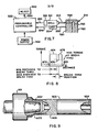
- Figures 5 through 8 disclose a workpiece 510 positioned to have material removed therefrom by a drill 512.
- the drill 512 rotates a drill bit 514 in a well known manner and the drill bit 514 is disposed so as to penetrate and pass through the workpiece 510 upon relative rotation of the bit 514 and the workpiece 510.
- the transducer 516 is associated with the drill 512 to sense the torque required to effect rotation of the bit 514 as it passes through the workpiece 510.
- the torque and force signal monitored by the transducer 516 are directed along the line.520 to a programmable controller 522.
- a linear variable differential transformer 524 is associated with the drill 512 and provides an output signal on line 526 which is directed to the programmable controller 522 and which is indicative of the position of the drill 512 with respect to the workpiece 510.
- the linear variable differential transformer 524 includes a probe 530 associated therewith which physically contacts a surface of the workpiece 510 and provides a variable output signal to the programmable controller 522 which is . indicative of the relative position of the cutting tool 514 with respect to the workpiece 510.
- Power supply 532 is provided for energizing the programmable controller 522 in a well known fashion.
- various quality characteristics of the workpiece 510 can be determined to determine whether the workpiece 510 is an acceptable workpiece meeting predetermined quality standards. For example, the thickness of the wall 518 can be sensed or the hardness of the material forming the wall 518 can be sensed. "Unusual" signatures not explained by-the condition of the tool or workpiece are generally indicative of machine wear or failure. The "unusual" signatures can be catalogued to aid in predicting the need for machine maintenance.
- Programmable controller 522 is utilized to generate a torque versus distance "signature" curve as is illustrated in Figure 6.
- the torque distance curve plots the torque sensed by the transducer 516 as the ordinate against the particular distance, as the abscissa, that the drill 512 travels as it is sensed by the linear variable differential transformer 524.
- This cycle will include the drill approaching the workpiece 510, the drill penetrating the workpiece 510 and then the drill exiting the workpiece 510 as it passes through the wall portion 518.
- One such complete movement of the drill 514 relative to the workpiece 510 is defined as a cycle. Each cycle will be broken into a plurality of increments during which torque sensed by the transducer 516 is measured.
- Figure 6 illustrates a typical torque versus distance curve for the drilling operation illustrated in Figure 5.
- the drill bit 514 approaches the wall. portion 518 of the workpiece 510, no torque will be exerted on the drill bit 514 by the workpiece 510 and thus the portion 640 of the curve will be generated which is indiative of no torque being exerted between the workpiece and the drill during the initial movement of the drill toward the workpiece.
- the torque will rapidly rise as indicated by drawing numeral 642. This function is known as leading edge turn on and can be utilized by the programmable controller 522 to locate the exact distance that a bit 514 has travelled before it has engaged the wall 518 of the workpiece 510.
- FIG 7 illustrates another example of a drilling operation wherein like parts are identified by like numerals.
- it is desired to drill a cross hole 760 into an existing cavity or cross port 762.
- initial contact establishes a sharply rising torque curve as shown by drawing numeral 872 in Figure 8 for "leading edge" electrical switching or turn-on.
- drawing numeral 874 Upon penetration of the drill bit 514 into the workpiece 510, the torque curve will flatten, as illustrated in Figure 8 by drawing numeral 874, for the portion of the torque-distance curve which is indicative of high torque; and torque remains relatively constant until the drill bit 514 enters the existing cavity 762.
- drawing numeral 876 Upon entering the existing cavity 762, the amount of torque required for the drill bit 514 to rotate will be decreased and the torque-distance curve will dip as indicated by drawing numeral 876 in Figure 8.
- one method of sensing both torque and lateral thrust applied to a tool 101 is to mount one strain gage 102 aligned with the longitudinal axis 103 of the holder 104 to sense axial or lateral force and a second strain gage 105 positioned at 45 degrees to the first to sense torqe by sensing shear strains in the plane of maximum shear as is well known to those skilled in the art of stress-strain measurement.
- a further set of problems are related to the resistance element in electrical resistance strain gages which are sometimes used as force sensors in machining operations. These strain gage sensors generally do not produce sufficient output when applied to machining tools or machine tool holders to permit reliable detection.
- One approach intended to overcome this problem is to substitute piezo electric elements have not met with widespread success because of their sensitivity to temperature and inability to reliably withstand the vibration encountered in machining operations.
- -It is an object of the present invention to t detect the combination of torque and thrust forces to aid in predicting machine and tool degradation.
- the elements of a resistance strain gage bridge network are placed at an angle other than zero, 45 or 90 degrees with respect to the longitudinal axis to enable a single gage element or the elements of an entire strain gage bridge circuit to provide an output which is indicative of both torque and axial thrust, thereby eliminating the need for two separate bridges to accomplish this task.
- the present invention eliminates the need for dual coupling devices. This is particularly important where coupling devices such as rotary transformers are required for transducer applications on rotating equipment.
- Machine tool parts are generally made from hard steels that have a substantial cross section or thickness which exhibits relatively little strain when stressed. Consequently, the output from the resistive strain gages used to measure this strain is relatively low. To overcome this problem, all the elements of the strain gage bridge are placed in the location of high strain to maximize the bridge output. Finally, high sensitivity detection equipment is used to detect the output signal of the bridge.
- the elements of a strain gage bridge are oriented on a rotating or stationary tool or workpiece in positions which enable them to act in a complementary fashion in the bridge circuit.
- One gage is oriented to sense only torque strains and the other gage is oriented to sense only axial load strains.
- the two gages are connected electrically in series to form a common arm of a Wheatstone bridge network and thus provide an additive or correlative single electrical output indicative of the combined strain effects of applied torque and axial loading. This technique may be applied even though the gages are set for a principal strain axis at an angle other than 90 degrees with respect to the longitudinal axis of the tool.
- the sensor body in the form of a standard tool holder is modified to provide region or a location of increased strain to which the gages, are applied for sensing the combined strain effects of applied torque and axial load.
- a special tool holder is provided with beams or webs to enable the gages of a single bridge circuit to sense the effects of both lateral thrust and torque.
- the special tool holder has the ends thereof, similar to the ends of a known tool . holder; however, the intermediate segment is entirely nonstandard and comprises a plurality of webs or beams separating the two ends from one another along their longitudinal axis.
- the drive which is supplied to one end of the tool holder is transmitted to the other end through the plurality of beams which are arranged to form a "twisted" hollow cruciform.
- the angle of the beams with respect to the flanges of the tool holder may be selected to optimize the sensitivity to torque and thrust as required for a particular application.
- the combined effect of axial loading and torque is sensed simultaneously by the same single strain sensor, since either type of loading produces a bending deflection of the beams.
- Sensitivity is increased by placing a plurality of strain gages of like orientation adjacent the ends of the beams in a position to sense bending compression strains in addition to bending tension strains.
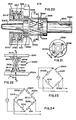
- FIG. 2 A Rotary transformer as used in conjunction with sensors such as strain gages for a rotating transducer is illustrated in Figures 2, 3 and 4.
- a carrier or source of alternating current 306 is connected to the primary winding 313 of the first transformer 301.
- the carrier or source of alternating current is referred to as the system excitation.
- the secondary winding 310 of the second transformer 304 couples the output voltage to an output or utilization device 307.
- the output signal is referred to as the system signal. It must be appreciated at this time that a single instrument can provide the functions of a carrier and utilization device and, in fact, such instruments may be calibrated to provide an output reading of the property to be measured by the transducer system.
- a known transducer system for measuring the torque on rotatable shaft 201.
- the excitation supplied to the input of the system is coupled to the transducer on shaft 201 by a first transformer 202.
- Transformer 202 includes a stationary or primary winding 203 receiving power from a connecting block 204 and a rotatable or secondary winding 205 connected to a strain gage transducer 206.
- a second transformer 207 having a rotatable or primary winding 210 coupled to the transducer and a stationary or secondary winding 208 transmitting an output signal to the connecting block 204.
- Both the transformers and the transducers are contained within a housing 209.
- strain gages are arranged in a bridge circuit with excitation being fed across opposite ports of the bridge and system signal being extracted from the remaining opposite ports.
- a schematic representation of this system is shown in figure 4 with the components on the left of the dashed line being mounted on the rotating shaft 201, while the components to the right of the dashed line are mounted on the stationary housing 209.
- Stationary windings 313 and 310 provide the system input and output, respectively. These windings are secured in the housing 209 on the stationary side, while the rotating winding 302 and 308 on the strain gage transducer 303 are all mounted on and rotate with the shaft 201.
- the strain gage transducer 303 is a bridge circuit which includes four legs having strain gage elements, 409 through 412.
- Figure 9 shows a rotating driven tool holder 903, having a chuck 901 provided with a tapered collet 905 in one end thereof with a tool 902 received therein.
- a shaded area 906 located to the right of the Morse taper is reserved for laying the strain gages.
- a bore 904 is provided in the right-hand end of holder 503.
- the present invention provides a tranducer emitting a single combined electrical signal indicating the strain effects of both torque and thrust.
- a plurality of strain gages may be connected in series or parallel or a combination of series and parallel in a common arm of the bridge.
- -one unit of a set of two identical, electrically connected and mechanically oriented strain gages is positioned at a first location where it will experience a force of one sense, such as tension, while the second unit is positioned where it will experience a complementary force of the opposite sense, such as compression.
- Units one and two are then connected in adjacent arms of a Wheatstone bridge. Each unit provides an output that is in effect added to the total output of the Wheatstone bridge.
- the stationary tool holder permits the leads to the strain gages to be brought off directly from the tool holder thereby eliminating any rotary coupling.
- the stationary tool holder permits the leads to the strain gages to be brought off directly from the tool holder thereby eliminating any rotary coupling.
- there is still an advantage in combining the signals from strain gages measuring different forces because the combined signal provides a single output for an operator or a computer to monitor. This greatly simplifies the operation for either the operator or the computer.
- only one signal conditioner and power supply are required.
- FIG. 10a there is shown in side elevation view a tool holder 1001 and Figure 10b shows and end elevation of the tool holder of Figure 10a.
- the tool holder 1001 contains an opening 1002 and threads 1004 at the right-hand end for the purposes of mounting the tool.
- the annular areas 1003 is machined away around the holder to provide a higher stress area for mounting strain gages in order to increase the elastic strain deformation and thus the sensitivity for use of electrical resistance strain gages.
- the stress in area 1002 is only raised by an amount to increase strain for gaging and not by an amount sufficient so to materially weaken the tool.
- FIGS 11 and 12 show a prior art torque transducer, indicated generally at 1100, comprising a tool holder 1101 having a configuration similar to that of Figure 10 with strain gages mounted in a machined out area 1102.
- the known transducer 1100 is instrumented with four strain gages spaced at 90° central angles about the periphery of the area 1102.
- Each of the gages 1103 A, B, C and D is oriented at approximately 45° to the axis of the holder 1101.
- Gages 1103C and 1103B sense tensile strains for an applied clockwise torque while gages 1103A and 1103D sense compressive strains.
- the gages are thus arranged to sense only torsional strains.
- the bridge network for the transducer 1100 is shown with tension serving gages 1103C and 1103B disposed on opposite legs of a Wheatstone bridge circuit. Compression strain sensing gages 1103D and 1103A are disposed oppositely in the remaining legs. The bridge output thus averages the compression and tensile strains due to shear stresses as is well known.
- the four gage bridge circuit of Figure 15 provides improved linearity and sensitivity over a single gage installation wherein dummy resistors are used to complete the Wheatstone bridge.
- Figures 13 and 14 show a prior art axial load transducer indicated generally at 1200 having a tool holder 1201 with a machined away region 1202 having strain gages mounted thereon.
- the device of Figure 13 is similar to that of Figure 11 with the exception of the orientation of the strain gages.
- the strain gages are arranged to be either perpendicular to or parallel with the longitudinal axis of the tool holder. This arrangement permits measurement of thrust rather than torque.
- the transducer 1200 has four strain gages 1203A, B, C and D disposed about the periphery thereof and spaced at 90° angles circumferentially thereabout.
- Gages 1203A and 1203C are oriented parallel to the axis of the holder 1201 for sensing axial compression.
- Strain gages 1203B and 1203D are oriented at right angles to the axis of the tool holder and sense in tension, the lateral Poisson-effect strains due to axial compression loading of the tool holder.
- FIG. 16 the bridge circuit for the transducer 1200 of Figure 13 is shown wherein compression sensing stain gages 1203A and 1203C are disposed in opposite legs of a Wheatstone bridge and tension strain gages 1203B and 1203D are disposed oppositely in the remaining legs of the bridge.
- the prior art transducers 1110 and 1200 each sense only one type of loading eg. torsional or axial and thus require separate bridge excitation and signal conditioning circuits in order to determine the overall loading for a tool holder if both types of gaging are employed on a common tool holder.
- a combined loading transducer indicated generally at 1700 is shown as comprising a tool holder 1701 having a machined surface 1702 of reduced diameter for increased strain and for receiving strain gages.
- the strain gages of transducer 1700 are shown disposed circumferentially about the periphery of the region 1702 of the tool holders 1701, in generally equally spaced arrangement.
- Four torsion serving gages 1703A, B, C & D are employed and are disposed in 90° arcuate spacing and oriented about principal axes rotated 45° from the vertical as shown for sensing strains due to an applied counter-clockwise torque in Figure 18.
- four strain gages 1704A, B, C and D are disposed for sensing strain due to axial compression loading.
- the two sets of gages 1703, 1704 are preferably disposed at the same axial station on the tool holder area 1702; however, it will be understood that the sets may be located at two axially spaced stations if it is desired to orient the torsion sensing gages 1704 on the vertical and horizontal principal axes of the tool holder . section, as are the compression sensing gages 1703.
- the Wheatstone bridge circuit for the non-rotating transducer embodiment 1700 of the present invention is shown for providing a single Wheatstone bridge circuit which, when balanced, provides an electrical signal indicative of the effects of combined axial and torsion loading. Comparison of such a bridge output with a desired signal trace as a function other parameters, such as tool travel can thus provide monitoring of a drilling or machining operation to provide indication of any of several failure modes, yet requires only a single bridge circuit.
- the compressive strain gages 1704A and 1704C are disposed in opposite arms of the bridge and are shown connected in series with the appropriate one of the compression sensing gages 1703B, 1703C of the torsion sensing set 1703.
- the Poisson-effect tension strain gages 1704B, 1704D are disposed oppositely in the remaining bridge arms and are also each connected in series with the appropriate one of the torsion tension gages 1703A, 1703D.
- the bridge network of Figure 19 for the transducer 1700 thus has each arm of the bridge comprising a torsion sensing and axial load sensing strain gage electrically in series giving the bridge arm maximum sensitivity to the combined effects of the overall loading.
- the plurality of gages in each arm of the bridge of Figure 19 is shown connected electrically in series, it will be understood that the plurality of gages in each arm may also be parallel connected to achieve the same combined-load sensing effect.
- the bridge arrangement for the transducer 1700 thus enables a single transducer having a single bridge circuit to replace two separate bridge circuits for separate indications of torsional and axial loading.
- the plural gages in each bridge are connected in series, however, it will be understood that the gages in each arm may also be connected in parallel.
- the invention has been illustrated in the transducer 1700 as adapted for stationary loading, it will be understood that the tool holder 1701 may also be gaged for rotation by employing rotary electrical coupling such as the transformer arrangement as described hereinabove with reference to Figure 4.
- an alternative embodiment of the invention is shown as embodied in the transducer indicated generally at 2600 in which a solid tool holder 2601 is provided with a reduced diameter strain-increasing portion 2602.
- a strain increasing portion could also be achieved by increasing the inside bore diameter of the tool holder, or by cross-drilling.
- the transducer 2600 embodies the invention in its simplest form in which a single strain gage is utilized to sense the combined strain effects of torsion and axial loading. It will be understood that the tool holder 2601 may otherwise be identical to the tool holder of Figures 11 and 13 in all respects except the strain gage mounting.
- the single strain gage 2603 is disposed at an acute angle 9 with respect to the longitudinal axis of the tool holder 2601 in order that the gage 2603 senses the combined strain effects of torsional and axial applied loads on the tool holder.
- the angle 8 is in the range 15-30° and preferably 22 1/2°.
- the Wheatstone bridge circuit for the single gage 2603 is shown in Figure 27 and employs dummy resistances 2603a, 2603b and 2603c respectively, one in each of the remaining arms of the bridge.
- the novel 22 1/2 0 orientation of the single gage 2603 permits the single gage to sense the combined strain effects of torsion and axial load in the reduced diameter region 2602, thereby providing sufficient sensitivity to render the transducer 2600 practical. If it is desired, increased sensitivity may be obtained, at additional cost, by adding additional strain gages for replacement of the dummy resistors. It will be understood that if additional strain gages are employed, they are oriented by an angle ⁇ differing somewhat the angle ⁇ employed for the single gage 2603 as will be described hereinafter.
- transducer 2800 having a tool holder 2801 with strainable structure comprising a strain increasing reduced diameter section with gaging surface 2802.
- the tool holder 2801 is similar to the tool holder 2601 of Figure 26.
- surface 2802 has mounted thereon a pair of strain gages 2803 and 2804 disposed spaced in quadrature on the surface 2802 subtending a central angle of 90° in a plane transverse to the loading axis as shown in Fig. 29.
- Gage 2803 has its strain sensing direction oriented at an acute angle ⁇ 1 in the range 15°-30°, and preferably 22 1/2° with the loading axis as shown in Figure 28 for.sensing compressive strains. It will be understood that gages 2803, 2804 may alternatively be spaced diametrically opposite in the plane of Figure 29.
- gage 2804 is oriented at an angle ⁇ 2 in the range 35-39° and preferably 37° with the axis of the holder 2801 for sensing tensile. strains.
- the bridge circuit for the transducer 2800 is shown in Figure 30 in which gages 2803 and 2804 are disposed individually in adjacent arms of the bridge for improved linearity and increased sensitivity. Dummy resistors 2805a and 2805b are provided in the remaining legs of the bridge. It will be understood that dummy resistors 2805a and 2805b may be replaced with additional active gages disposed in quadrature with gages 2803, 2804 on gaging surface 2802 for a further increase in sensitivity.
- transducers 2600 and 2800 may be employed either as stationary transducers, or as rotating transducers employing a rotary transformer coupling for excitation and bridge output coupling as is shown in Figures 2, 3 and 4.
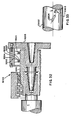
- the transducer 2000 comprises a tool holder 2001 having the right hand end portion 2002 provided with an internal Morse taper 2003 adapted for receiving a rotating tool therein in frictional driving engagement.
- the opposite end portion 2004 of tool holder 2001 has provided thereon an external Morse taper 2005 and is adapted for frictional rotary driving engagement with a driven shaft (not . shown) having a corresponding internal taper.
- the region of the tool holder 2001 intermediate tapers 2003, 2005 is hollowed out and comprises a plurality of circumferentially spaced generally axially extending webs or beams 2006 which serve to interconnect the end portions 2002, 2004.
- the beams 2006 are each disposed at an acute angle with the longitudinal axis of rotation of the tool holder and are preferably disposed in circumferentially equally spaced arrangement.
- Each of the beams 2006 has its ends rigidly attached to respectively one of the opposite portions 2002, 2004 of the tool holder 2001 such that any applied axial or torsional loading of the portions 2002, 2004 results in bending deflection of beams 2006.
- the beams 2006 each have a transverse section which has a thickness, denoted "t” in Figure 21, which is substantially less than the radial width, denoted "w” in Figure 21.
- t thickness
- w radial width
- the ratio of w/t is in the range 2-5.
- each beam 2006 with the axis of the tool holder is preferably in the range 15-45°.
- the preferred arrangement of the strain gage in transducer 2000 is shown in detail in Figure 22 for two of the beams 2006.
- the angle "4" may be optimized to enhance the strain effect of either torsional or axial loading. Keeping “0" near the lower limit enhances torsional strain; whereas keeping “ ⁇ ” near the upper limit enhances axial loading effects...
- the transducer 2000 is illustrated in Figure 22 as preferably having two strain gages on each beam, forming a full bridge circuit; however, it will be understood that a partial bridge circuit may be employed utilizing only two strain gages.
- the strain gages are disposed in pairs adjacent the ends of the beams 2006 in the region of maximum bending movement, with the gages disposed on opposite faces of the beam 2006. Referring to Figure 22, strain gages 2007 and 2008 comprise such a pair. Where the axial loading is compressive, as denoted by the arrows "P" in Figure 22, gage 2007 senses compressive bending strains and gage 2008 senses tensile bending strains.
- the invention requires only a single strain gage on one of the beams 2006.
- the output signal of the bridge is reduced where only one strain gage is employed, the bending deflection of the beams 2006 is sufficient to produce a useable transducer with only a single strain gage since any bending of the beams 2006 is a result of the combined efforts of torsion and axial loading.
- any one of the torsion gages 2008, 2009, 2011 or 2014 may be employed.
- the single gage 2008 is employed in one arm of a Wheatstone bridge, and the remaining arms each contain a dummy resistor 2008a, 2008b and 2008c respectively.
- beams 2006 will be somewhat different for an applied counter clockwise torque as compared to an oppositely applied torque load, it will be understood the beams 2006 respond in bending to either sense of applied torque or to axial loading and thus the strain gages 2007, 2008 read either tensile or compressive strains resulting from the combined effects of the transducer loading.
- gages 2009, 2010 which are likewise mounted on opposite faces of another one of the beams 2006 and adjacent the upper end thereof. Although gages 2009, 2010 are disposed adjacent the upper end of the second one of the beams 2006, it will be understood that they may alternatively be disposed adjacent the lower end of the second beam 2006.
- Gages 2007, 2008, 2009 and 2010 thus may be connected each in a separate arm of a Wheatstone bridge circuit, as shown in Figure 23 with the tension sensing gages 2008, 2009 disposed in opposite arms of the bridge.
- the single bridge circuit of Figure 23 thus gives a single output responsive to the combined effects of any applied torque and any axial loading of the transducer 2000.
- the transducer 2000 By sensing bending strains of the beams or webs at their root, the transducer 2000 provides a high degree of electrical strain sensitivity to torque and axial loading in a single bridge output signal. As described above, by varying the angle " ⁇ ", the effects of either torque or axial loading may be enhanced in the combined bridge signal.
- the overall sensitivity of the transducer to any given applied load is determined by the values chosen for-the beam dimension "t" and "w” and the number and length of the beams.
- gages 2009, 2010 may be eliminated and gages 2007, 2008 may be connected in adjacent arms of a bridge (not shown) and dummy resistances employed for the remaining arms.
- an additional four strain gages 2011, 2012, 2013 and 2014 may optionally be employed for even greater sensitivity and accuracy.
- optional gages 2011-14 are shown in Figure 22 as mounted in pairs with one pair on the lower end of the same beams 2006 as gages 2007-2010.
- the optional gages 2011-2014 may alternatively be mounted in pairs on either end of the remaining two (not shown in Figure 22) of the four beams 2006.
- FIG. 24 the Wheatstone bridge circuit for the eight gages 2007-2013 is shown. Torsion strain gages 2008, 2014 are connected in series in one arm of the bridge and tension strain gages 2009, 2011 are connected in series on the opposite arm of the bridge. Compressive strain gages 2007 and 2009 are connected in series on a third arm of the bridge, with compressive strain gages 2012 and 2010 series connected in the remaining bridge arm opposite therefrom.
- the eight gage strain sensing bridge network of Figure 24 provides averaging of the strains in all four beams 2006. The additional averaging of the bridge of Figure 24 is obtained at additional cost as compared to the bridge of Figure 23.
- the rotating transducer 2000 has an inner bearing race 2015 received over the outer periphery of end 2004 of the tool holder and supports rotating coils 2016, 2017 of input and output transformers indicated generally at 2019, 2018.
- Output transformer 2018 has a stationary secondary coil 2022 and input transformer 2019 has a stationary primary cbil-2019 mounted on housing 2021.
- the rotary transformer arrangement of Figure 20 thus may be similar to that described in Figures 2 and 3 in construction and function is generally well known in the art.
- the unique feature of the transducer 2000 of Figure 20 is not in the excitation and pickup technique, but rather that a single bridge circuit yields an output which includes the combined strain effects of axial and torsional loading.
- the unique web or beam sensing elements 2006 of transducer 2000 provide a high degree of strain sensitivity by sensing bending of the beams in response to axial or torsional loading of the transducer.
- the present invention thus provides a novel and unique way or means of sensing the combined strain effects of torsional and axial loading and requires in its simplest form only a single strain gage in a single bridge circuit to yield a single electrical signal indicative of the combined strain effects. However, additional strain gages may be added for increased sensitivity.
- the single bridge circuit strain gage transducer of the present invention may be employed in either stationary or rotating applications experiencing combined torsional and axial loading.
- Transducer 3000 includes an input end means comprising hub 3001 having an axially extending stub shaft at 3002 extending leftward therefrom in Figure 31.
- Stub shaft 3002 has an external Morse taper thereon which is received in frictional driving engagement with a corresponding internal Morse taper provided in shaft S.
- Hub 3001 has an annular hub extension 3003 extending leftwardly therefrom and disposed concentrically over stub shaft 3002. Extension 3003 has mounted thereon for rotation therewith the secondary coil of an excitation rotary transformer, indicated generally at 3004, and spaced axially therefrom is provided the primary coil of an output rotary transformer indicated generally at 3005.
- the primary coil of rotary transformer 3004 and the secondary coil of rotary transformer 3005 are each respectively mounted on a stationary housing 3006 in a manner similar to the rotating coupling shown in Figure 4.
- the hub 3001 is journaled for rotation in the housing 3006 by means of suitable bearings 3007, 3008 disposed on the extension 3003.
- Hub 3001 has a plurality of radially outwardly extending spokes provided thereon, two of which 3009, 3010 are shown in Figure 31 as having their outer end connected to an outer annular flange 3011.
- the spokes 3009, 3010 comprise elastically deflectable beams elongated in the radial direction and preferably having a rectangular transverse section similar to the beams 3006 in Figure 21.
- a second outer annular flange 3012 is provided and is disposed axially adjacent flange 3011 and secured thereto by suitable fastening means as for example, bolts 3013, 3014.
- Second annular flange 3012 has attached thereto in a circumferentially spaced arrangement about the inner periphery thereof a plurality of radially inwardly extending spokes or beams 3015, 3016 having the radially inner ends attached to-a second hub 3017.
- the second hub 3017 has attached thereto in rigid driving engagement a stub shaft 3018 which extends axially in a rightward direction as shown. in Figure 31.
- Stub shaft 3018 has provided in the end thereof an internal Morse taper 3019 for receiving therein, in frictional engagement, a suitable rotating tool (not shown).
- Hub 3017 is thus suspended from flange 3012 by the beams 3015, 3016 and is axially spaced from hub 3001 by a desired amount to permit limited axial movement of one hub with respect to the other before mutual contact occurs.
- At least one of the spokes 3009, 3010, 3015 and 3016 has provided thereon a plurality of strain gages 3020, 3021 which are disposed near the inner end of the spoke closely adjacent hub 3001.
- the strain gages 3020, 3021 are disposed so as to sense logitudinal bending strains in the beam or spoke 3009.
- the gages 3020, 3021 are mounted with one gage such as 3020 lying in a plane parallel to the axis of rotation and the second gage 3021 lying in a plane perpendicular to the axis of rotation. This arrangement enables gage 3020 to sense torsional bending deflection of the spoke 3009 and gage 3021 to sense axial deflection of spoke 3009.
- the gages 3020, 3021 are connected electrically together in a common arm of a Wheatstone bridge circuit similar to that shown in Figure 19. It will be understood that gages 3020, 3021 may be either connected electrically in series or parallel in a common bridge arm.
- transducer 3000 is thus an alternative way of practicing the teachings of the invention described with respect to Figure 22, in that combined effect of torsional and axial loading are sensed by strain gaging a common bending beam to detect compressive and tensile bending stresses in the beam due to the applied loading.
- FIG. 32 another embodiment of the invention is shown for a rotary transducer 3200, wherein an input shaft T engages a driving hub 3201 which as a plurality of rows of axially and circumferentially spaced spokes 3202, 3203 extending radially outwardly therefrom and connected to a common outer flange 3204.
- Flange 3204 is actually axially connected to a second flange hub 3205 for receiving a rotating tool (not shown).
- the spoke 3202, 3203 are strain gaged in a manner identical to that described with respect to the transducer 3000 in Figure 31.
- the present invention thus provides a unique load transducer having in its simplest form a single strain gage sensing the combined strain effects of applied axial and torsional loading and producing a single bridge output signal for the combined loading.
Applications Claiming Priority (2)
| Application Number | Priority Date | Filing Date | Title |
|---|---|---|---|
| US574446 | 1984-01-27 | ||
| US06/574,446 US4555955A (en) | 1984-01-27 | 1984-01-27 | Combination loading transducer |
Publications (1)
| Publication Number | Publication Date |
|---|---|
| EP0156073A2 true EP0156073A2 (de) | 1985-10-02 |
Family
ID=24296169
Family Applications (1)
| Application Number | Title | Priority Date | Filing Date |
|---|---|---|---|
| EP84308614A Withdrawn EP0156073A2 (de) | 1984-01-27 | 1984-12-11 | Gerät zur kombinierten Kraftmessung |
Country Status (4)
| Country | Link |
|---|---|
| US (1) | US4555955A (de) |
| EP (1) | EP0156073A2 (de) |
| JP (1) | JPS60186354A (de) |
| CA (1) | CA1230501A (de) |
Cited By (4)
| Publication number | Priority date | Publication date | Assignee | Title |
|---|---|---|---|---|
| WO1989004469A1 (fr) * | 1987-11-13 | 1989-05-18 | Logabex | Procede de realisation de capteurs de mesure d'efforts spatiaux et capteurs obtenus |
| DE9014037U1 (de) * | 1990-10-09 | 1990-12-20 | Emuge-Werk Richard Glimpel Fabrik Fuer Praezisionswerkzeuge, 8560 Lauf, De | |
| WO2014170052A1 (de) * | 2013-04-19 | 2014-10-23 | Robert Bosch Gmbh | Messvorrichtung zur messung von lagerkippmomenten einer lageranordnung |
| WO2015011489A1 (en) * | 2013-07-25 | 2015-01-29 | Brunel University | Cutting tool with surface acoustic wave sensor |
Families Citing this family (17)
| Publication number | Priority date | Publication date | Assignee | Title |
|---|---|---|---|---|
| JPS6226532A (ja) * | 1985-07-19 | 1987-02-04 | リチヤ−ド エル.ジエンキンス | アイソメトリツク制御装置 |
| US5481184A (en) * | 1991-12-31 | 1996-01-02 | Sarcos Group | Movement actuator/sensor systems |
| US5651284A (en) * | 1995-06-22 | 1997-07-29 | Liberty Technologies, Inc. | Strain gage method for measuring thrust and torque on valve stems that does not require calibrations against a known thrust and torque |
| JP3227403B2 (ja) * | 1997-04-09 | 2001-11-12 | 豊田工機株式会社 | センサ、工作機械の状態判別装置及び状態判別方法 |
| DE102008015005A1 (de) * | 2008-03-19 | 2009-09-24 | Mtu Aero Engines Gmbh | Spannfutter-integriertes Kraftmesssystem |
| US10874466B2 (en) | 2012-06-21 | 2020-12-29 | Globus Medical, Inc. | System and method for surgical tool insertion using multiaxis force and moment feedback |
| US10646280B2 (en) | 2012-06-21 | 2020-05-12 | Globus Medical, Inc. | System and method for surgical tool insertion using multiaxis force and moment feedback |
| FR3003486B1 (fr) * | 2013-03-25 | 2015-05-22 | Ct Tech De L Ind Du Decolletage | Porte-plaquette pour machine-outil |
| DE102014103240A1 (de) | 2014-03-11 | 2015-10-01 | Pro-Micron Gmbh & Co. Kg | Verfahren zur Einrichtung und/oder Überwachung von Betriebsparametern einer Werkstückbearbeitungsmaschine |
| EP3292930B1 (de) * | 2016-09-09 | 2023-03-01 | Sandvik Intellectual Property AB | Schneidwerkzeug und verfahren zur schätzung der biegung der schneidkante |
| US10488281B2 (en) * | 2017-08-05 | 2019-11-26 | Interface, Inc. | Axial force pressure transducer |
| CN112888926A (zh) * | 2018-10-10 | 2021-06-01 | 基斯特勒控股公司 | 工具和用于测量工具力的方法 |
| ES2894144T3 (es) * | 2019-03-15 | 2022-02-11 | Siemens Ag | Máquina herramienta con orientación optimizada de amortiguadores de vibración |
| CN114981626A (zh) * | 2019-11-15 | 2022-08-30 | 直观外科手术操作公司 | 扩展桥xy力传感器 |
| EP3967449A1 (de) * | 2020-09-09 | 2022-03-16 | Hartmetall-Werkzeugfabrik Paul Horn GmbH | Werkzeughalter und werkzeugsystem mit einem solchen werkzeughalter |
| CN112649130B (zh) * | 2020-12-29 | 2022-03-08 | 上海海事大学 | 一种医用穿刺活检针界面交互力学性能一体化测试方法 |
| CN113059401B (zh) * | 2021-04-01 | 2022-07-12 | 杭州爱科科技股份有限公司 | 一种自动感应刀具受力方向和大小的纠偏装置 |
Family Cites Families (4)
| Publication number | Priority date | Publication date | Assignee | Title |
|---|---|---|---|---|
| US2767577A (en) * | 1954-01-13 | 1956-10-23 | Gilbert Charles Allen | X-beam strain gauge dynamometer |
| US2909764A (en) * | 1955-08-25 | 1959-10-20 | Boeing Co | Angular position transducer |
| US3855857A (en) * | 1973-05-09 | 1974-12-24 | Schlumberger Technology Corp | Force-measuring apparatus for use in a well bore pipe string |
| JPS5888631A (ja) * | 1981-11-24 | 1983-05-26 | Yotaro Hatamura | スラスト・トルク検出素子 |
-
1984
- 1984-01-27 US US06/574,446 patent/US4555955A/en not_active Expired - Fee Related
- 1984-12-11 EP EP84308614A patent/EP0156073A2/de not_active Withdrawn
-
1985
- 1985-01-17 CA CA000472322A patent/CA1230501A/en not_active Expired
- 1985-01-28 JP JP60015250A patent/JPS60186354A/ja active Pending
Cited By (6)
| Publication number | Priority date | Publication date | Assignee | Title |
|---|---|---|---|---|
| WO1989004469A1 (fr) * | 1987-11-13 | 1989-05-18 | Logabex | Procede de realisation de capteurs de mesure d'efforts spatiaux et capteurs obtenus |
| FR2623284A1 (fr) * | 1987-11-13 | 1989-05-19 | Logabex | Capteur d'efforts spatiaux |
| US5063788A (en) * | 1987-11-13 | 1991-11-12 | Logabex S.A.R.L. | Process for producing sensors for measuring spatial forces and sensors obtained |
| DE9014037U1 (de) * | 1990-10-09 | 1990-12-20 | Emuge-Werk Richard Glimpel Fabrik Fuer Praezisionswerkzeuge, 8560 Lauf, De | |
| WO2014170052A1 (de) * | 2013-04-19 | 2014-10-23 | Robert Bosch Gmbh | Messvorrichtung zur messung von lagerkippmomenten einer lageranordnung |
| WO2015011489A1 (en) * | 2013-07-25 | 2015-01-29 | Brunel University | Cutting tool with surface acoustic wave sensor |
Also Published As
| Publication number | Publication date |
|---|---|
| CA1230501A (en) | 1987-12-22 |
| JPS60186354A (ja) | 1985-09-21 |
| US4555955A (en) | 1985-12-03 |
Similar Documents
| Publication | Publication Date | Title |
|---|---|---|
| US4555955A (en) | Combination loading transducer | |
| Brinksmeier | Prediction of tool fracture in drilling | |
| CA1217952A (en) | Compensated rheometer | |
| AU552459B2 (en) | Force, torque and displacement sensor for machine tools | |
| US4341113A (en) | Inspection system for heat exchanger tubes | |
| CA1143934A (en) | Inspection system for heat exchanger tubes | |
| US20150027238A1 (en) | Method and measuring system for determining deformations of a geometric body with the aid of force measuring sensors or deformation measuring sensors | |
| JPH03500745A (ja) | 回転機械加工用に取り付けられた工具チップによって描かれる半径を自動的に測定する装置及び方法 | |
| JPS62247222A (ja) | トルク検出方法及びその検出装置 | |
| US4802274A (en) | Method of determining worn rotary tool | |
| CN110505938A (zh) | 具有测量功能的转轴端部 | |
| JPH0246349B2 (de) | ||
| US6905393B2 (en) | Method for simultaneous machining and measuring parameters of a surface being subjected to machining | |
| CN110048554A (zh) | 用于监控磁性轴承装置的方法 | |
| US3818334A (en) | Determining cutting tool force by measuring electrical resistance of a bearing | |
| JPH0249844B2 (de) | ||
| GB2090976A (en) | Apparatus for measuring bolt prestressing | |
| US4545239A (en) | Method and apparatus for controlling the quality of tires | |
| JP2505811B2 (ja) | スピンドルヘツドの工具損傷検出装置 | |
| JPH0246348B2 (ja) | Koguhorudaagatakenshutsusochi | |
| JPH09174384A (ja) | 棒状回転部材の曲げ力検出装置 | |
| JPH02303752A (ja) | 工作機械用トルク検出器 | |
| JPH03149158A (ja) | トルク、スラスト、曲げ力検知スピンドル | |
| JPH07113588B2 (ja) | 力‐モーメント・センサ | |
| KR102531964B1 (ko) | 제어된 열전도를 갖는 로봇 힘/토크 센서 |
Legal Events
| Date | Code | Title | Description |
|---|---|---|---|
| PUAI | Public reference made under article 153(3) epc to a published international application that has entered the european phase |
Free format text: ORIGINAL CODE: 0009012 |
|
| AK | Designated contracting states |
Designated state(s): DE FR GB IT SE |
|
| STAA | Information on the status of an ep patent application or granted ep patent |
Free format text: STATUS: THE APPLICATION HAS BEEN WITHDRAWN |
|
| 18W | Application withdrawn |
Withdrawal date: 19860818 |
|
| RIN1 | Information on inventor provided before grant (corrected) |
Inventor name: HODGES, JOHN BLACK Inventor name: ELLWOOD, THOMAS JOHN Inventor name: AMLANI, KISH DEVIDAS Inventor name: MORGAN, PAUL WILLIAM |