EP0156071A2 - Behälter für Schüttgut mit einer entlang einen Linear-Weg beweglichen Tür - Google Patents
Behälter für Schüttgut mit einer entlang einen Linear-Weg beweglichen Tür Download PDFInfo
- Publication number
- EP0156071A2 EP0156071A2 EP84308553A EP84308553A EP0156071A2 EP 0156071 A2 EP0156071 A2 EP 0156071A2 EP 84308553 A EP84308553 A EP 84308553A EP 84308553 A EP84308553 A EP 84308553A EP 0156071 A2 EP0156071 A2 EP 0156071A2
- Authority
- EP
- European Patent Office
- Prior art keywords
- door
- opening
- bulk material
- threaded shaft
- shell
- Prior art date
- Legal status (The legal status is an assumption and is not a legal conclusion. Google has not performed a legal analysis and makes no representation as to the accuracy of the status listed.)
- Granted
Links
- 239000013590 bulk material Substances 0.000 title claims abstract description 43
- 230000002401 inhibitory effect Effects 0.000 claims 2
- 239000000463 material Substances 0.000 description 19
- 238000007789 sealing Methods 0.000 description 7
- 230000006835 compression Effects 0.000 description 4
- 238000007906 compression Methods 0.000 description 4
- 230000004048 modification Effects 0.000 description 4
- 238000012986 modification Methods 0.000 description 4
- XAGFODPZIPBFFR-UHFFFAOYSA-N aluminium Chemical compound [Al] XAGFODPZIPBFFR-UHFFFAOYSA-N 0.000 description 3
- 229910052782 aluminium Inorganic materials 0.000 description 3
- 230000005484 gravity Effects 0.000 description 3
- 238000003466 welding Methods 0.000 description 3
- 229910000831 Steel Inorganic materials 0.000 description 2
- 238000011109 contamination Methods 0.000 description 2
- 238000006073 displacement reaction Methods 0.000 description 2
- 235000013305 food Nutrition 0.000 description 2
- 239000010959 steel Substances 0.000 description 2
- 239000000126 substance Substances 0.000 description 2
- 229910000906 Bronze Inorganic materials 0.000 description 1
- 230000004913 activation Effects 0.000 description 1
- 239000010974 bronze Substances 0.000 description 1
- 239000000356 contaminant Substances 0.000 description 1
- KUNSUQLRTQLHQQ-UHFFFAOYSA-N copper tin Chemical compound [Cu].[Sn] KUNSUQLRTQLHQQ-UHFFFAOYSA-N 0.000 description 1
- 238000007599 discharging Methods 0.000 description 1
- 230000010355 oscillation Effects 0.000 description 1
- 239000002574 poison Substances 0.000 description 1
- 231100000614 poison Toxicity 0.000 description 1
- 230000008092 positive effect Effects 0.000 description 1
Images

Classifications
-
- B—PERFORMING OPERATIONS; TRANSPORTING
- B65—CONVEYING; PACKING; STORING; HANDLING THIN OR FILAMENTARY MATERIAL
- B65D—CONTAINERS FOR STORAGE OR TRANSPORT OF ARTICLES OR MATERIALS, e.g. BAGS, BARRELS, BOTTLES, BOXES, CANS, CARTONS, CRATES, DRUMS, JARS, TANKS, HOPPERS, FORWARDING CONTAINERS; ACCESSORIES, CLOSURES, OR FITTINGS THEREFOR; PACKAGING ELEMENTS; PACKAGES
- B65D90/00—Component parts, details or accessories for large containers
- B65D90/54—Gates or closures
- B65D90/62—Gates or closures having closure members movable out of the plane of the opening
- B65D90/626—Gates or closures having closure members movable out of the plane of the opening having a linear motion
-
- B—PERFORMING OPERATIONS; TRANSPORTING
- B65—CONVEYING; PACKING; STORING; HANDLING THIN OR FILAMENTARY MATERIAL
- B65D—CONTAINERS FOR STORAGE OR TRANSPORT OF ARTICLES OR MATERIALS, e.g. BAGS, BARRELS, BOTTLES, BOXES, CANS, CARTONS, CRATES, DRUMS, JARS, TANKS, HOPPERS, FORWARDING CONTAINERS; ACCESSORIES, CLOSURES, OR FITTINGS THEREFOR; PACKAGING ELEMENTS; PACKAGES
- B65D90/00—Component parts, details or accessories for large containers
- B65D90/54—Gates or closures
Definitions
- the present invention relates in general to bulk material containers, and more particularly to a bulk material container with a door movable over a rectilinear path.
- Bulk material containers with side doors or outlets are employed-for storing and handling materials containing contaminants or containing food products and chemicals requiring contamination free conditions or for transporting corrosive or dangerous materials. In handling poisons or the like, an operator should not be exposed to the dangerous material.
- the sealing of the door as well as the activation of the door is of concern in protecting the operator from exposure to or contact with dangerous material and also to prevent the contamination of food products and chemicals.
- a bulk material container in which a door for an opening in a wall of the container is screw actuated for movement along a rectilinear path for opening and closing the opening.
- the present invention provides an arrangement for actuating a door over a rectilinear path for the opening and closing of an opening in a bulk material container employing screw actuating means.
- a feature of the present invention is that a gasket surrounds the opening and the door is moved to compress the gasket to form a seal during the closure of the opening.
- a feature of the present invention is that the door for the opening can be opened and closed from either side of the bulk material container.
- screw shaft can be rotated from either end to move the door over a rectilinear path for the opening and closing of an opening.
- Another feature of the present invention is that the extent or degree of closure or the opening of a door relative to the walls or seal surrounding an opening can be positively controlled.
- Another feature of the present invention is that the bulk material stored in the container does not come into contact with the operating parts of the mechanism that imparts a rectilinear movement to the door.
- Another feature of the present invention is that the door is opened and closed mechanically with a positive action that does not rely on the force of gravity or the force applied by the weight of the material being discharged from the container through vibrations or oscillations.
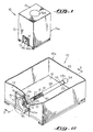
- FIG. 1 Illustrated in Figure 1 is a suitable bulk material container 10 having a suitable opening or discharge opening 11 (Figure 2) formed in a side wall 12 thereof.
- the walls of the container 10 define a shell 10a.
- an adapter plate or door frame 13 Secured to the wall 12 and surrounding the opening 11 is an adapter plate or door frame 13.
- a door 15 is arranged to open and close the opening 11 through movement along a rectilinear path. While the preferred embodiment employs a round door 15 with a cylindrical wall surrounding the opening 11, it is within the contemplation of the present invention that the door 15 may be configured in different shapes and the opening 11 and the opening formed in the door frame 13 will have a configuration conforming to the contour of the door 15.
- the discharge opening 11 ( Figure 2) is formed in the wall 12 of the container 10 for gravity unloading.
- a screw- type conveyor can be employed for discharging material or any other suitable arrangement can be employed for material discharge, such as tilting, shaking and jolting of the container 10.
- An opening 16a formed in a wall 17 may be employed as a material inlet or service opening for the container 10.
- the door 15 For moving the door 15 over a rectilinear path, the door 15 comprises an integrally formed hub 25 (Figure 3).
- the door 15 is disposed exteriorly of the container 10.
- the door 15 is moved outwardly away from the container 10 when the opening 11 is opened and is moved toward the wall 12 of the container 10 when the opening 11 is closed.
- the door 15 can be disposed inwardly of the container 10. Unèer this circumstance, the door 15 is moved toward the wall 12 to close the opening 11 and is moved away from the wall 12 to open the opening 11.
- the hub 25 is telescopically received by a bearing tube 26 made of suitable material, such as aluminum.
- the bearing tube 26 is of sufficient thickness to prevent distortion in the hub 25 during the actuation of the door 15.
- Surrounding the hub 25 at the forward end thereof is a seal and shaft wiper 20 and a seal housing 21.
- Angularly disposed struts or guides 24 are fixedly secured to the seal housing 21 and the wall 12 of the container 10 for supporting the bearing tube 26, the hub 25 and the seal housing 21. It is within the contemplation of the present invention to fixedly secure the struts 24 to the wall 12 of the container 10 and the bearing tube 26.
- the threaded bushing 27 is fixedly positioned within the container 10.
- the threads of the bushing are preferably made of steel.
- a suitable tube or shaft housing 28 Fixed to the free end of the threaded bushing 27 by welding or the like is a suitable tube or shaft housing 28. Fixed to the shaft housing 28 by welding or the like is a stop block 52. A tube 29 is fixed to the stop block 52 by weldment or the like. A wall 53 of the container 10 has an adjustment sleeve or tube 53a fixed thereto, such as by welding, which, in turn, is welded or secured to the tube 29. An opening 54 is formed in the wall 53 in alignment with a threaded shaft 40. The wall 53 of the container 10 faces the wall 12 of the container 10. The adjustment sleeve 53a supports the tubes 26-29 from the wall 53 of the container 10.
- a suitable axial opening or bore 35 extends through the hub 25 of the door 15.
- the shaft 40 is made of suitable material, such as steel.
- the threaded section 41 of the shaft 40 is disposed --in threaded engagement with the internal-threads of the "- fixedly positioned housing 27.
- the shaft 40 has a flange type bushing 42a fixed thereto to provide an enlarged diameter section that forms a shoulder 42 for engagement with the hub 25 of the door 15.
- a thrust bearing and bushing 45 At the end of shaft 40 adjacent the door 15 is a thrust bearing and bushing 45 that engages the end of the hub 25 opposite from the end of the hub 25 that engages the shoulder 42.
- the bushings 42a and 45 are bronze bushings.
- Fixed to the shaft 40 by weldment or the like is a nut 46, which is adjacent to the bearing and bushing 45.
- Rotation of the nut 46 by a long handle wrench or other suitable tool imparts rotation to the shaft 40.
- the shaft 40 moves relative to the threaded bushing 27 over a rectilinear path-axially of the fixedly positioned tubes 26-29 to impart movement to the door 15 through its hub 25 over a rectilinear path to either open the opening 11 or to close the opening 11.
- a nut 49 similar to the nut 46, is fixed to the end of the shaft 40 adjacent to the wall 53 by a weldment or the like.
- a long handle wrench -or suitable tool can then impart rotation to the shaft 40 at the opening 54 of the wall 53. The action will then be similar to that described for the rotation of the nut 46.
- a stop collar 55 is fixed to the shaft 40 and engages the stop block 52 for limiting the movement of the shaft 40.
- a suitable gasket or O-ring 50 is fixed to the round door 15 and is arranged to engage the adapter plate 13 fixed to the wall 12 of the container 10, when the door 15 closes the opening 11.
- the gasket 50 forms a seal between the door 15 and the adapter plate 13 of the wall 12 of the container 10, when the round door 15 closes the opening 11.
- the sealing compression of the gasket 50 is controlled by-the rotation of the shaft 40. Once the gasket 50 engages the plate 13, the door 15 is inhibited from rotating. However, the door 15 will continue to move over a rectilinear path to control the sealing compression of the gasket 50.
- An effective seal is created between the door 15 of the plate 13 of the wall 12 about the entire edge of the round door 15. While in the preferred embodiment, the seal 50 is fixed to the round door 15, a seal could be attached to the plate 13 surrounding the opening 11 to be engaged by the round door 15.
- the shaft 40 is formed with a reduced diameter section 51 extending from the threaded section 41 to the nut 49. After the door 15 is moved away from the plate 13 to open the opening 11, there is movement of the door 15 to increase the displacement between the door 15 and the opening 11.
- FIG 4 Illustrated in Figure 4 is a modification of the shaft 40.
- the modified shaft 40 ( Figure 4) does not include the reduced diameter section 51 ( Figure 3) but rather has a threaded section 41 to which the stop 55 is affixed. In this manner, the displacement of the door 15 from the plate 13 is controlled entirely by the rotation of the shaft 40 ( Figure 4) from the door end.
- the block 52, section 51 and nut 49 ( Figure 3) have been omitted.
- the tubes 28 and 29 constitute a single tube.
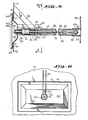
- FIG. 5 and 6 Illustrated in Figures 5 and 6 is a modification of the door 15 (Figure 3).
- a rectangular door 60 ( Figure 6) is employed and in lieu of a round opening 11 ( Figure 3) a rectangular opening 61 ( Figure 6) is employed.
- the door 60 is configured to conform to the shape of the opening 61.
- the arrangement disclosed in Figures 5 and 6 can be employed when a door other than a round door is employed.
- the struts 24 in Figures 5 and 6 are fixed to the wall 12 and the bearing tube 26. Fixed to the door 60 and directed toward the interior of the container 10 for positioning between the spaced struts 24 is a door aligner 63.
- the door aligner 63 moves into the space between the struts or alignment guides 24 to key or orient the door 60 for alignment with the opening 61 so that upon closure the door 60 is precisely located for closing the opening 61.
- the tendency for the door 60 to rotate while moving over the rectangular path at closure with the opening 61 is inhibited by the door aligner 63 moving in the space between struts or alignment guides 24.
- a gasket 64 embraces the perimetric edges of the door 60 ( Figure 5).
- a frame 13 surrounds the opening 61 to provide a rigid surface for the seating of the gasket 64 and to assist in the guidance of the door 60 for proper orientation. Once the door 60 is in place, the frame 13 affords protection to the door 60 from external forces applied during the handling of the container.
- the door 60 is recessed at 60a to protect the operating parts employed in the opening and the closing of the door 60 such as the nut 46 and the shaft 40. Similarly, the recessed area 54 performs a similar function for the nut 49 and the shaft 40.
- the frame 13, in the preferred embodiment, is fixed to the wall 12 on the exterior side and is flush along the bottom edge so as not to trap material during the unloading of material. Trapped material on the door seat lends itself to causing an inadequate seal for the door.
- the gasket 64 is fixed to the door 60 and is arranged to engage the door frame 13 fixed to the wall 12 of the container, when the door 60 closes the opening 61.
- the gasket 64 forms a seal between the door 60 and the door frame 13, when the door 60 closes the opening 61.
- the sealing compression of the gasket 64 is controlled by the axial movement of the door 60.
- the door aligner 63 and the guides 24 restrict any rotational movement of the door 60 and align the door 60 for accurate seating relative to the opening 61.
- the door 60 will continue to move over a rectilinear path to control the sealing compression of the gasket 64.
- An effective seal is created between the door 60 and the frame 13 of the wall 12-about all the edges of the --door 60 through the gasket 64.
- the gasket 50 ( Figures 3 and 4) is a hollow 0-ring. When not compressed, the gasket 50 has an annular cross-sectional area. When compressed for forming a seal, the exposed area of the gasket 50 assumes a flat configuration for sealing engagement. While reference is made to the closure and opening of the opening 11 formed in the wall 12, it is apparent that the concept of the present invention is equally applicable to the opening formed in the door frame 13. In the conventional container 10, well-known internal corner closures and baffles will be employed to direct bulk material toward the discharge opening 11 during the discharge of bulk material from the container 10.
Landscapes
- Engineering & Computer Science (AREA)
- Mechanical Engineering (AREA)
- Closures For Containers (AREA)
- Vehicle Step Arrangements And Article Storage (AREA)
- Closing And Opening Devices For Wings, And Checks For Wings (AREA)
- Wing Frames And Configurations (AREA)
- Filling Or Emptying Of Bunkers, Hoppers, And Tanks (AREA)
Priority Applications (1)
| Application Number | Priority Date | Filing Date | Title |
|---|---|---|---|
| AT84308553T ATE43320T1 (de) | 1984-03-29 | 1984-12-07 | Behaelter fuer schuettgut mit einer entlang einen linear-weg beweglichen tuer. |
Applications Claiming Priority (2)
| Application Number | Priority Date | Filing Date | Title |
|---|---|---|---|
| US06/594,840 US4858791A (en) | 1984-03-29 | 1984-03-29 | Bulk material container with a door movable over a rectilinear path |
| US594840 | 1984-03-29 |
Publications (3)
| Publication Number | Publication Date |
|---|---|
| EP0156071A2 true EP0156071A2 (de) | 1985-10-02 |
| EP0156071A3 EP0156071A3 (en) | 1987-02-25 |
| EP0156071B1 EP0156071B1 (de) | 1989-05-24 |
Family
ID=24380627
Family Applications (1)
| Application Number | Title | Priority Date | Filing Date |
|---|---|---|---|
| EP84308553A Expired EP0156071B1 (de) | 1984-03-29 | 1984-12-07 | Behälter für Schüttgut mit einer entlang einen Linear-Weg beweglichen Tür |
Country Status (4)
| Country | Link |
|---|---|
| US (1) | US4858791A (de) |
| EP (1) | EP0156071B1 (de) |
| AT (1) | ATE43320T1 (de) |
| DE (1) | DE3478299D1 (de) |
Families Citing this family (1)
| Publication number | Priority date | Publication date | Assignee | Title |
|---|---|---|---|---|
| US5139183A (en) * | 1990-05-14 | 1992-08-18 | Whirlpool Corporation | Ice crusher ice chute door |
Family Cites Families (11)
| Publication number | Priority date | Publication date | Assignee | Title |
|---|---|---|---|---|
| US544403A (en) * | 1895-08-13 | Faucet | ||
| US953370A (en) * | 1909-03-24 | 1910-03-29 | Keystone Iron Works | Valve. |
| US1278520A (en) * | 1915-05-26 | 1918-09-10 | Kellar Thomason Company | Valve. |
| US1490417A (en) * | 1920-08-16 | 1924-04-15 | Chesnutt John Loucien | Acetylene-gas generator |
| US2190723A (en) * | 1936-12-24 | 1940-02-20 | American Car & Foundry Co | Top operated outlet valve |
| US2676610A (en) * | 1952-07-05 | 1954-04-27 | Miller Mfg Co | Valve with ball bearing mounted seal |
| US2877867A (en) * | 1957-07-29 | 1959-03-17 | Caterpillar Tractor Co | Fluid compartment drain plug |
| DE1216795B (de) * | 1962-10-06 | 1966-05-12 | Seelemann & Soehne Anton | Einstellvorrichtung fuer den senkrechten Auslassschieber eines Behaelters |
| US3280996A (en) * | 1964-05-13 | 1966-10-25 | Hoover Ball & Bearing Co | Bins and apparatus for discharging bins |
| GB1092568A (en) * | 1966-06-29 | 1967-11-29 | Sutton And Sons Ltd | Dispenser |
| CH441093A (de) * | 1966-07-14 | 1967-07-31 | Meynadier & Cie Ag | Vorrichtung zum dosierten Austragen von schüttfähigem Gut |
-
1984
- 1984-03-29 US US06/594,840 patent/US4858791A/en not_active Expired - Lifetime
- 1984-12-07 AT AT84308553T patent/ATE43320T1/de not_active IP Right Cessation
- 1984-12-07 EP EP84308553A patent/EP0156071B1/de not_active Expired
- 1984-12-07 DE DE8484308553T patent/DE3478299D1/de not_active Expired
Also Published As
| Publication number | Publication date |
|---|---|
| US4858791A (en) | 1989-08-22 |
| DE3478299D1 (en) | 1989-06-29 |
| EP0156071A3 (en) | 1987-02-25 |
| ATE43320T1 (de) | 1989-06-15 |
| EP0156071B1 (de) | 1989-05-24 |
Similar Documents
| Publication | Publication Date | Title |
|---|---|---|
| JP2524317B2 (ja) | 濃縮ウランのための輸送用容器 | |
| US20080174113A1 (en) | Connection assembly | |
| JP2002522307A (ja) | コンテナ用密閉バルブ | |
| CN1303345A (zh) | 用于容器衬袋并具有衬袋刺破/刺穿装置的阀装置 | |
| US5944300A (en) | Bag and box valve system | |
| US5069371A (en) | Bulk material container with a door movable over a rectilinear path | |
| US4858791A (en) | Bulk material container with a door movable over a rectilinear path | |
| US4923101A (en) | Bulk material container with a door movable over a rectilinear path | |
| EP0092008A1 (de) | Behälter mit Schmetterlingsklappe | |
| US4376451A (en) | Container | |
| FI63365B (fi) | Saett och apparat foer att utan nedsmutsning eller nedstoftning av omgivningen oeppna och toemma innehaollet ur emballeringsfat eller dylikt foer vaetskor korn- och pulverformigt gods eller dylikt | |
| US5954218A (en) | Open head container cover | |
| GB2053418A (en) | Vessel with discharge means | |
| US7270787B2 (en) | Centrifuge sample jar and closure | |
| KR100719499B1 (ko) | 수집, 운반 및 저장용 용기 | |
| JP2604421B2 (ja) | ストップ弁 | |
| CN211190127U (zh) | 一种具有自动开盖功能的反应釜 | |
| EP4076875A1 (de) | Verfahren zum automatischen wiederaufbau der verstärkungsarchitektur eines verbundmaterials | |
| US6364179B1 (en) | Telescoping valve assembly and method for use thereof | |
| US3261505A (en) | Bulk container with tapping adapter | |
| JPS5816506Y2 (ja) | パレツト付きコンテナ− | |
| CZ9903462A3 (cs) | Výpustný ventil pro nádrľe na dopravu tekutých nebezpečných látek | |
| CN1420832A (zh) | 带盖板的液体容器 | |
| GB2373242A (en) | Emptying device for a bulk container | |
| JPH0411990Y2 (de) |
Legal Events
| Date | Code | Title | Description |
|---|---|---|---|
| PUAI | Public reference made under article 153(3) epc to a published international application that has entered the european phase |
Free format text: ORIGINAL CODE: 0009012 |
|
| AK | Designated contracting states |
Designated state(s): AT DE FR GB SE |
|
| PUAL | Search report despatched |
Free format text: ORIGINAL CODE: 0009013 |
|
| AK | Designated contracting states |
Kind code of ref document: A3 Designated state(s): AT DE FR GB SE |
|
| 17P | Request for examination filed |
Effective date: 19870808 |
|
| 17Q | First examination report despatched |
Effective date: 19880311 |
|
| GRAA | (expected) grant |
Free format text: ORIGINAL CODE: 0009210 |
|
| AK | Designated contracting states |
Kind code of ref document: B1 Designated state(s): AT DE FR GB SE |
|
| PG25 | Lapsed in a contracting state [announced via postgrant information from national office to epo] |
Ref country code: SE Effective date: 19890524 Ref country code: AT Effective date: 19890524 |
|
| REF | Corresponds to: |
Ref document number: 43320 Country of ref document: AT Date of ref document: 19890615 Kind code of ref document: T |
|
| REF | Corresponds to: |
Ref document number: 3478299 Country of ref document: DE Date of ref document: 19890629 |
|
| ET | Fr: translation filed | ||
| PLBE | No opposition filed within time limit |
Free format text: ORIGINAL CODE: 0009261 |
|
| STAA | Information on the status of an ep patent application or granted ep patent |
Free format text: STATUS: NO OPPOSITION FILED WITHIN TIME LIMIT |
|
| 26N | No opposition filed | ||
| PGFP | Annual fee paid to national office [announced via postgrant information from national office to epo] |
Ref country code: GB Payment date: 19930927 Year of fee payment: 10 |
|
| PGFP | Annual fee paid to national office [announced via postgrant information from national office to epo] |
Ref country code: FR Payment date: 19931126 Year of fee payment: 10 |
|
| PGFP | Annual fee paid to national office [announced via postgrant information from national office to epo] |
Ref country code: DE Payment date: 19931221 Year of fee payment: 10 |
|
| PG25 | Lapsed in a contracting state [announced via postgrant information from national office to epo] |
Ref country code: GB Effective date: 19941207 |
|
| GBPC | Gb: european patent ceased through non-payment of renewal fee |
Effective date: 19941207 |
|
| PG25 | Lapsed in a contracting state [announced via postgrant information from national office to epo] |
Ref country code: FR Effective date: 19950831 |
|
| PG25 | Lapsed in a contracting state [announced via postgrant information from national office to epo] |
Ref country code: DE Effective date: 19950901 |
|
| REG | Reference to a national code |
Ref country code: FR Ref legal event code: ST |