EP0155746B1 - Elément élastique de support de têtes magnétiques flottantes du type Winchester - Google Patents
Elément élastique de support de têtes magnétiques flottantes du type Winchester Download PDFInfo
- Publication number
- EP0155746B1 EP0155746B1 EP19850300130 EP85300130A EP0155746B1 EP 0155746 B1 EP0155746 B1 EP 0155746B1 EP 19850300130 EP19850300130 EP 19850300130 EP 85300130 A EP85300130 A EP 85300130A EP 0155746 B1 EP0155746 B1 EP 0155746B1
- Authority
- EP
- European Patent Office
- Prior art keywords
- flexure
- mount
- axis
- dimple
- tongue
- Prior art date
- Legal status (The legal status is an assumption and is not a legal conclusion. Google has not performed a legal analysis and makes no representation as to the accuracy of the status listed.)
- Expired
Links
Images

Classifications
-
- G—PHYSICS
- G11—INFORMATION STORAGE
- G11B—INFORMATION STORAGE BASED ON RELATIVE MOVEMENT BETWEEN RECORD CARRIER AND TRANSDUCER
- G11B5/00—Recording by magnetisation or demagnetisation of a record carrier; Reproducing by magnetic means; Record carriers therefor
- G11B5/48—Disposition or mounting of heads or head supports relative to record carriers ; arrangements of heads, e.g. for scanning the record carrier to increase the relative speed
- G11B5/58—Disposition or mounting of heads or head supports relative to record carriers ; arrangements of heads, e.g. for scanning the record carrier to increase the relative speed with provision for moving the head for the purpose of maintaining alignment of the head relative to the record carrier during transducing operation, e.g. to compensate for surface irregularities of the latter or for track following
- G11B5/60—Fluid-dynamic spacing of heads from record-carriers
- G11B5/6005—Specially adapted for spacing from a rotating disc using a fluid cushion
-
- G—PHYSICS
- G11—INFORMATION STORAGE
- G11B—INFORMATION STORAGE BASED ON RELATIVE MOVEMENT BETWEEN RECORD CARRIER AND TRANSDUCER
- G11B5/00—Recording by magnetisation or demagnetisation of a record carrier; Reproducing by magnetic means; Record carriers therefor
- G11B5/48—Disposition or mounting of heads or head supports relative to record carriers ; arrangements of heads, e.g. for scanning the record carrier to increase the relative speed
- G11B5/58—Disposition or mounting of heads or head supports relative to record carriers ; arrangements of heads, e.g. for scanning the record carrier to increase the relative speed with provision for moving the head for the purpose of maintaining alignment of the head relative to the record carrier during transducing operation, e.g. to compensate for surface irregularities of the latter or for track following
Definitions
- This invention relates to an arrangement for mounting magnetic recording transducers and particularly for improved flexure mounts for "Winchester sliders" adapted for magnetic disk recording.
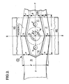
- FIG. 1 shows, in plan view, a somewhat conventional flexure mounting for mounting an air-bearing slider ABS of a type well known in the art of high-speed, high-density magnetic recording on disk media.
- Workers in the art recognize that random access, magnetic disk storage systems typically use read/write transducers mounted on an air-bearing slider such as slider ABS (in partial outline in FIG. 1, and understood as adapted to be "flown" over a disk recording surface).
- Flexure mount I is classically intended to accommodate optimum slider orientation during acceleration/deceleration of the adjacent disk surface, and during negotiation of disk surface irregularities ("asperities" or microscopic variances from perfect surface flatness and smoothness).
- Such a flexure I will be understood as attached to a conventional load beam LB (not shown, but well known in the art, e.g., being spot- welded thereto).
- the load beam is fastened to an actuator arm which supports an entire "head-arm assembly” (HAA) above a subject disk surface.
- HAA head-arm assembly
- Flexure I comprises a relatively flat, thin flexure leaf 10 projected out from supporting load beam LB to terminate at a free distal tip portion AA.
- a central, separately-flexing tongue portion T is cantilevered back from tip AA, the flexure 10 being cut-out to accommodate tongue T, as known in the art.
- Tongue T includes a dimple D for attachment of slider ABS as known in the art.
- a pair of like, relatively rectangular flexure beam-segments 11, 11' surround tongue T, connecting tip AA to the flexure body 10.
- Tongue T This somewhat conventional flexure design I might be. characterized as “rectangular”, since it presents parallel rectangular beam-segments 11, 11' supporting flexure tip AA. Tongue T will be understood as offset from the plane of the flexure body, being “tilted” (e.g., about 2°) above the parallel beam segments 11, 11'. Tongue T has a relatively complex shape, being somewhat rectangular at its supported, end adjacent tip AA, and being widened somewhat about dimple D in a pair of like symmetrical rectangular protrusions Dp, Dp ' and terminating at a tongue tip Tp, which is somewhat pointed.
- Bonding is further complicated by the relatively narrow clearance about tongue T and the difficulty of disposing of surplus adhesive during slider bonding.
- This adhesive is quite apt to "bridge" the relatively narrow clearance and bar, or interfere with, tongue flex. Also, air pockets are apt to develop in the adhesive mass.
- tongue T prevents one from using convenient, inexpensive die-stamping methods to form the part. Instead, one typically must turn to a costly chemical-etch method (apt to cause stress corrosion and metal fatigue, especially where an etchant residue is left).
- IBM Technical Disclosure Bulletin, Vol. 26, No. 6, November 1983 New York, USA, pages 2920-2921 disclose a head suspension assembly with an internally preloaded dimple. According to this disclosure the contact force between the flexure dimple and the suspension is increased by introducing an internal preload without altering the final geometry of the suspension assembly.
- the invention provides a flexure mount for carrying a magnetic recording transducer body adapted to be brought into operative relation with a passing record surface, this mount comprising an elongate flexure strip (20) having a distal tip (2-AA), a tongue section (TT) cantilevered back from this tip, and a pair of like beam-segments (21, 21') flanking the tongue section to join said tip to the proximate end of the mount, said tongue section being provided with a dimple (DD) to which said transducer body (ABS) is attached by means of adhesive, characterised in that said beam-segments are each necked-down identically intermediate their length, to exhibit a minimum width along an axis (R-R) through the centre of said dimple transverse to a length axis (L) of said flexure strip, whereby any predisposition for said transducer body to rotate in either direction about said axis is reduced.
- this mount comprising an elongate flexure strip (20)
- a flexure mount in accordance with the invention will be seen to be cheaper and easier to fabricate, to exhibit greater pitch-stiffness, and to better balance the slider in the roll direction (more uniform "roll compliance”; little or no “roll bias”, with less than 5-10% “slider-height” differential commonly seen).
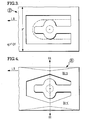
- FIG. 2 One embodiment of an "arched flexure” design according to the invention is shown in FIG. 2 as “arch flexure” II, wherein the size and shape of the flexure tongue TT and those of the flanking flexure beams 21, 21' are modified (flexure II being the same as flexure I in FIG. 1, except where otherwise specified).
- flexure support II is adapted to suspend a slider ABS (as above), and comprises a flexure- leaf (pref. stainless steel) body 20 with a tongue TT cut-out adjacent the distal tip 2-AA of body 20 and with sidebeam-segments 21, 21' flanking tongue TT and joining tip 2-AA to the body 20.
- a flexure- leaf pref. stainless steel
- tongue TT will be seen as presenting a considerably increased dimpling-area surrounding dimple DD (the dimple is otherwise the same), presenting a somewhat uniform ring of material (ring of radius y surrounding dimple DD). Otherwise, the tongue width is about the same (cf. width w adjacent flexure tip 2-AA about the same as in FIG. 1 embodiment), except about dimple DD, where width is smoothly and symmetrically increased to a maximum along roll axis R-R. Tongue TT terminates in a tip portion TTP with a blunt-nose end and width w. (The "v" shaped" cutout opposite tip TTP can be replaced by a "square end", etc.).
- This new "bulbous" tongue shape will be seen as increasing the area around dimple. DD.
- dimpling is simpler and better, with considerably less distortion of the tongue (flatness) (more material to draw-from ion the dimpling process).
- pitch-stiffness and pitch torsion
- increased bonding area thus improving bonding of the slider to the flexure.
- relief holes h, h' are provided through tongue TT, preferably on both sides of dimple DD, as will be seen in FIG. 2. (The location, number, size and shape of these holes is a matter of choice).
- the "arched" flexure beams 21, 21' are also "necked-down" (narrowed in width) medially to exhibit a prescribed reduced width b along roll-axis R-R (b ⁇ a).
- R-R roll-axis
- the span H' of arch flexure II (that is the distance between beam center lines) is here increased above that of a more conventional "rectangular" flexure (e.g., I in FIG. 1). This is believed to increase resistance to pitch - e.g., a span H' about twice the span H of "rectangular" flexure I will be found to increase pitch-stiffness on the order of 25% for flexure geometry which is otherwise typical.
- flexure III is further modified by necking-down the beam-segments (enlarged cut-out flanking tongue) - as shown in FIG. 4 for flexure IV.
- beam-segments bb-s, bb-s' are identically necked-down in width symmetrically, medially of their length - to a minimum width along the roll axis R-R of the flexure IV. This will be understood as performed to effect a prescribed reduction (e.g., elimination) of "roll bias".
Claims (5)
Applications Claiming Priority (2)
| Application Number | Priority Date | Filing Date | Title |
|---|---|---|---|
| US57398284A | 1984-01-26 | 1984-01-26 | |
| US573982 | 1995-12-18 |
Publications (2)
| Publication Number | Publication Date |
|---|---|
| EP0155746A1 EP0155746A1 (fr) | 1985-09-25 |
| EP0155746B1 true EP0155746B1 (fr) | 1988-03-30 |
Family
ID=24294195
Family Applications (1)
| Application Number | Title | Priority Date | Filing Date |
|---|---|---|---|
| EP19850300130 Expired EP0155746B1 (fr) | 1984-01-26 | 1985-01-09 | Elément élastique de support de têtes magnétiques flottantes du type Winchester |
Country Status (4)
| Country | Link |
|---|---|
| EP (1) | EP0155746B1 (fr) |
| JP (1) | JPS60209984A (fr) |
| CA (1) | CA1246216A (fr) |
| DE (1) | DE3562057D1 (fr) |
Families Citing this family (13)
| Publication number | Priority date | Publication date | Assignee | Title |
|---|---|---|---|---|
| JPS6190079U (fr) * | 1984-11-16 | 1986-06-11 | ||
| JPS6277472U (fr) * | 1985-11-01 | 1987-05-18 | ||
| US4724500A (en) * | 1986-08-14 | 1988-02-09 | Tandon Corporation | Mechanism for preventing shock damage to head slider assemblies and disks in rigid disk drive |
| JP2533522B2 (ja) * | 1987-03-23 | 1996-09-11 | 株式会社日立製作所 | トランスデユ−サ支持装置 |
| JP2602299B2 (ja) * | 1988-09-28 | 1997-04-23 | 富士通株式会社 | ヘッド支持機構 |
| US4987507A (en) * | 1989-03-02 | 1991-01-22 | Digital Equipment Corporation | Flexure guide for straight-line motion |
| US5014144A (en) * | 1989-06-13 | 1991-05-07 | Hitachi, Ltd. | Magnetic head slider supporting apparatus |
| US5291359A (en) * | 1991-04-29 | 1994-03-01 | Hutchinson Technology Incorporated | Head suspension assembly including a flexure having rails arranged for interfacing with a head ramp |
| JPH0798949A (ja) * | 1993-09-16 | 1995-04-11 | Internatl Business Mach Corp <Ibm> | サスペンション・システム |
| JPH07210838A (ja) * | 1993-12-03 | 1995-08-11 | Read Rite Corp | 磁気ヘッドサスペンションアセンブリ |
| US5877923A (en) * | 1995-08-21 | 1999-03-02 | Read Rite Corporation | Head suspension assembly |
| US5936804A (en) * | 1997-11-26 | 1999-08-10 | Quantum Corporation | Impact features on suspensions for improved damage resiliancy in disk drives |
| US9567357B2 (en) | 2011-06-24 | 2017-02-14 | Biointeractions Ltd. | Biocompatible, biomimetic ampholyte materials |
Family Cites Families (5)
| Publication number | Priority date | Publication date | Assignee | Title |
|---|---|---|---|---|
| US3593330A (en) * | 1969-01-27 | 1971-07-13 | Computer Communications Inc | Web-like spring support for magnetic transducer |
| US3599193A (en) * | 1969-02-24 | 1971-08-10 | Data Products Corp | Trifurcated gimbal head mount |
| US3668668A (en) * | 1970-12-07 | 1972-06-06 | Rca Corp | Transducing head mount apparatus |
| US3931641A (en) * | 1974-08-22 | 1976-01-06 | International Business Machines Corporation | Transducer suspension mount apparatus |
| US4167765A (en) * | 1978-07-27 | 1979-09-11 | International Business Machines Corporation | Transducer suspension mount apparatus |
-
1985
- 1985-01-09 EP EP19850300130 patent/EP0155746B1/fr not_active Expired
- 1985-01-09 DE DE8585300130T patent/DE3562057D1/de not_active Expired
- 1985-01-24 JP JP1176185A patent/JPS60209984A/ja active Pending
- 1985-01-25 CA CA000472947A patent/CA1246216A/fr not_active Expired
Also Published As
| Publication number | Publication date |
|---|---|
| JPS60209984A (ja) | 1985-10-22 |
| DE3562057D1 (en) | 1988-05-05 |
| CA1246216A (fr) | 1988-12-06 |
| EP0155746A1 (fr) | 1985-09-25 |
Similar Documents
| Publication | Publication Date | Title |
|---|---|---|
| EP0155746B1 (fr) | Elément élastique de support de têtes magnétiques flottantes du type Winchester | |
| US5711063A (en) | Method of forming a suspension fabricated from silicon | |
| US6011671A (en) | Head gimbal assembly for limiting dimple separation for a data storage device | |
| US5353181A (en) | Etched suspension system | |
| US5526204A (en) | Low drag liquid bearing recording head | |
| US5850320A (en) | Head-gimbal assembly with reduced vertical spacing envelope and alignment structures | |
| EP0576904A1 (fr) | Tête d'enregistrement à film mince | |
| US4449155A (en) | Gimbal assembly for flying magnetic transducer heads | |
| EP0007548B1 (fr) | Dispositif pour l'enregistrement magnétique en duplex sur un support flexible | |
| US6958889B2 (en) | Slider with a compliant transducer interface | |
| US5650894A (en) | Gimballed spring arm having a reinforced plate for use with a magnetic head | |
| US5057953A (en) | Head slider suspension assembly load beam having a fundamental mode vibration characteristic in the range of about 2000 hertz to about 4000 hertz | |
| US5455727A (en) | Transducer suspension assembly with a first pair of flanges for raising the resonant frequency and a second pair of flanges for increasing stiffness | |
| JPH08124338A (ja) | 磁気ヘッド支持機構 | |
| US20030218832A1 (en) | Magnetic head slider, support therefor and magnetic disk unit | |
| EP0465465B1 (fr) | Ensemble a tete magnetique | |
| US6697226B1 (en) | Disc drive suspension having tip stiffener | |
| US5825589A (en) | Low stiffness apparatus for supporting a read/write transducer head slider | |
| JPS61230687A (ja) | 記録変換器用スライダ | |
| JPH03219473A (ja) | トランスデューサ支持装置 | |
| US7113370B2 (en) | Slanted mounting for preload flat suspension | |
| JPS63149888A (ja) | 浮動ヘツドスライダ支持機構 | |
| JPH09106528A (ja) | 磁気ヘッドアセンブリ及び磁気ディスク装置 | |
| JP2902521B2 (ja) | 磁気ディスクおよび磁気ヘッドならびに磁気記録装置 | |
| JPH01128278A (ja) | 磁気デイスク用ヘッド支持体 |
Legal Events
| Date | Code | Title | Description |
|---|---|---|---|
| PUAI | Public reference made under article 153(3) epc to a published international application that has entered the european phase |
Free format text: ORIGINAL CODE: 0009012 |
|
| 17P | Request for examination filed |
Effective date: 19850115 |
|
| AK | Designated contracting states |
Designated state(s): BE DE FR GB IT NL |
|
| 17Q | First examination report despatched |
Effective date: 19861215 |
|
| GRAA | (expected) grant |
Free format text: ORIGINAL CODE: 0009210 |
|
| AK | Designated contracting states |
Kind code of ref document: B1 Designated state(s): BE DE FR GB IT NL |
|
| REF | Corresponds to: |
Ref document number: 3562057 Country of ref document: DE Date of ref document: 19880505 |
|
| ET | Fr: translation filed | ||
| ITF | It: translation for a ep patent filed |
Owner name: MODIANO & ASSOCIATI S.R.L. |
|
| BECN | Be: change of holder's name |
Effective date: 19880330 |
|
| PLBE | No opposition filed within time limit |
Free format text: ORIGINAL CODE: 0009261 |
|
| STAA | Information on the status of an ep patent application or granted ep patent |
Free format text: STATUS: NO OPPOSITION FILED WITHIN TIME LIMIT |
|
| 26N | No opposition filed | ||
| NLS | Nl: assignments of ep-patents |
Owner name: UNISYS CORPORATION TE BLUE BELL, PENNSYLVANIE, VER |
|
| NLT1 | Nl: modifications of names registered in virtue of documents presented to the patent office pursuant to art. 16 a, paragraph 1 |
Owner name: UNISYS PERIPHERALS CORPORATION TE SANTA CLARA, CAL |
|
| REG | Reference to a national code |
Ref country code: FR Ref legal event code: TP Ref country code: FR Ref legal event code: CD |
|
| REG | Reference to a national code |
Ref country code: GB Ref legal event code: 732 |
|
| BECH | Be: change of holder |
Free format text: 881222 *UNISYS CORP. |
|
| PGFP | Annual fee paid to national office [announced via postgrant information from national office to epo] |
Ref country code: FR Payment date: 19911227 Year of fee payment: 8 |
|
| PGFP | Annual fee paid to national office [announced via postgrant information from national office to epo] |
Ref country code: GB Payment date: 19911231 Year of fee payment: 8 |
|
| PGFP | Annual fee paid to national office [announced via postgrant information from national office to epo] |
Ref country code: DE Payment date: 19920129 Year of fee payment: 8 |
|
| ITTA | It: last paid annual fee | ||
| PGFP | Annual fee paid to national office [announced via postgrant information from national office to epo] |
Ref country code: NL Payment date: 19920131 Year of fee payment: 8 |
|
| PGFP | Annual fee paid to national office [announced via postgrant information from national office to epo] |
Ref country code: BE Payment date: 19920207 Year of fee payment: 8 |
|
| PG25 | Lapsed in a contracting state [announced via postgrant information from national office to epo] |
Ref country code: GB Effective date: 19930109 |
|
| PG25 | Lapsed in a contracting state [announced via postgrant information from national office to epo] |
Ref country code: BE Effective date: 19930131 |
|
| BERE | Be: lapsed |
Owner name: UNISYS CORP. Effective date: 19930131 |
|
| PG25 | Lapsed in a contracting state [announced via postgrant information from national office to epo] |
Ref country code: NL Effective date: 19930801 |
|
| GBPC | Gb: european patent ceased through non-payment of renewal fee |
Effective date: 19930109 |
|
| NLV4 | Nl: lapsed or anulled due to non-payment of the annual fee | ||
| PG25 | Lapsed in a contracting state [announced via postgrant information from national office to epo] |
Ref country code: FR Effective date: 19930930 |
|
| PG25 | Lapsed in a contracting state [announced via postgrant information from national office to epo] |
Ref country code: DE Effective date: 19931001 |
|
| REG | Reference to a national code |
Ref country code: FR Ref legal event code: ST |