EP0155733A1 - Apparat zum Falten einer Schachtel oder eines Troges aus einem Zuschnitt - Google Patents
Apparat zum Falten einer Schachtel oder eines Troges aus einem Zuschnitt Download PDFInfo
- Publication number
- EP0155733A1 EP0155733A1 EP85200376A EP85200376A EP0155733A1 EP 0155733 A1 EP0155733 A1 EP 0155733A1 EP 85200376 A EP85200376 A EP 85200376A EP 85200376 A EP85200376 A EP 85200376A EP 0155733 A1 EP0155733 A1 EP 0155733A1
- Authority
- EP
- European Patent Office
- Prior art keywords
- conveyor
- blank
- mould
- box
- folding
- Prior art date
- Legal status (The legal status is an assumption and is not a legal conclusion. Google has not performed a legal analysis and makes no representation as to the accuracy of the status listed.)
- Withdrawn
Links
Images


Classifications
-
- B—PERFORMING OPERATIONS; TRANSPORTING
- B31—MAKING ARTICLES OF PAPER, CARDBOARD OR MATERIAL WORKED IN A MANNER ANALOGOUS TO PAPER; WORKING PAPER, CARDBOARD OR MATERIAL WORKED IN A MANNER ANALOGOUS TO PAPER
- B31B—MAKING CONTAINERS OF PAPER, CARDBOARD OR MATERIAL WORKED IN A MANNER ANALOGOUS TO PAPER
- B31B50/00—Making rigid or semi-rigid containers, e.g. boxes or cartons
- B31B50/26—Folding sheets, blanks or webs
- B31B50/44—Folding sheets, blanks or webs by plungers moving through folding dies
Definitions
- the invention relates to an apparatus for folding a box or trough from a preformed blank of cardboard, corrugated cardboard, duplex cardboard, coated paper, synthetic material, wood such as plywood or multiply, or other sheet or plate material, said blank being provided in advance with folding seams and consisting at least of a portion for the bottom and portions separated therefrom by such folding seams for the upright walls of the box or trough to be folded, said apparatus comprising at least means for holding the blank in a predetermined position, a first conveyor for moving the blank transversely to its plane from said position, a mould provided in the path of said conveyor and having a mould cavity which is surrounded by a set of folding members and has a bottom area extending transversely to said path and corresponding to the bottom portion of the box or trough to be folded, stops projecting into said bottom area and adapted to arrest the movement of said bottom portion and also a second conveyor for removing the blank folded in the mould out of the latter.
- the invention has for its object to provide an apparatus of the kind referred to here-above, in which the said disadvantages of the known apparatuses are avoided as much as possible.
- the first conveyor includes at least one supporting member mounted for reciprocation between two end positions and having a suction head attached thereto adapted to be moved through the bottom plane of the mould cavity and provided with suction openings or cups fitted for connection to a suction conduit, said suction head being adapted, during operation, to engage the blank held in the predetermined position on the lower side of its portion meant for the bottom of the box or trough and to pull, during its active stroke, the blank past said set of folding members into the cavity of the mould.
- a next blank when either being contained in a magazine or lying on or between supporting members, can already be positioned in a place above or next to the mould and be ready to be engaged by the first conveyor, when the folding of the preceding blank is still going on. Waiting for the moment that the mandrel has left said place is then unnecessary. Thereby the speed of the apparatus can be considerably increased.
- the means for holding the blank in a predetermined position include a magazine for a stack of blanks, said magazine being so arranged and constructed, as to enable, during operation, the suction head of the first conveyor to pull each time the lowermost blank of said stack or each time the end blank of the stack which faces with its lower side to the outside out of the magazine and to carry it to the mould.
- An other apparatus may advantageously be constructed so that the means for holding the blank in a predetermined position include two parallel composite guide bars meant for guiding the blank from a place out of the reach to a place defining said predetermined position within the reach of the first conveyor, said guide bars holding the blank at least in the latter place at two opposite edges and supporting it on its lower side in narrow margins or parts thereof adjacent to said edges.
- This apparatus has the advantage that cn the blank lying in its place above the first conveyor the filling for the box or trough may be disposed before the folding process starts.
- this apparatus may comprise a magazine for blanks, a third conveyor mounted for reciprocation between two end positions, said third conveyor comprising at least one suction head for engaging the lower side of the blank and moving same in a direction transverse to its plane to the guide bars, and a fourth conveyor provided with a carrier member for moving the blank along said guide bars to the place within the reach of the first conveyor.
- the second conveyor may be so mounted for reciprocation between two end positions, as to remove, during its active stroke, from the mould, the part of the box or trough folded in the mould and extending with its bottom in a plane containing the bottom area of the mould cavity, whereas a second set of folding members for folding the portions of the blank still to be folded after the blank has passed the mould may be provided on both sides and, if necessary, above the path of the second conveyor.
- the second conveyor may then comprise at least one suction member which engages, in the position at the beginning of the active stroke of said conveyor, the bottom of the folded part of the box or trough contained in the mould on its lower side near the bottom edge which is leading in the direction of said stroke, said suction member holding said bottom till the folding operation of the second set of folding members has been completed.
- This holding of the bottom of the box or trough in the place thereof referred to is favourable for the folding of the blank parts.
- the second conveyor In order to have the transport of said second conveyor carried out reliably, it is recommended to provide the second conveyor also with a carrier member which is adapted to be put, at the beginning of the active stroke of said conveyor, into an active position behind the upright and, seen in the direction of said stroke, rear wall of the folded part of the box or trough contained in the mould but, during the inactive stroke of said conveyor, into an inactive position.
- This carrier member may also be used to push the boxes or troughs which have been previously folded in the apparatus out of the apparatus.
- the set of folding members surrounding the mould cavity as well as the set of folding members on both sides and, if necessary, above the path of the second conveyor consists of two groups, of which one group is attached to a stationary part and the other group is attached to an adjustable part of the apparatus, said latter part being adjustable in a direction parallel to the plane of the path of the second conveyor and transversely to the direction of movement thereof.
- one guide bar with its portion for guiding and supporting the blank at an edge thereof may be attached to a stationary part and the other guide bar with its portion for guiding and supporting the blank at an other edge thereof may be attached to an adjustable part of the apparatus, said latter part being adjustable in a direction parallel to the plane of the path bordered by the two guide bars and transversely to said bars.
- the latter For driving the first conveyor the latter may be connected to an endless chain mounted for reciprocation between two end positions and coupled directly or indirectly through a transmission mechanism with one end of a link, of which the other end is pivotally connected with a point of an other endless chain, which is driven by a motor in one direction.
- the second conveyor may be coupled directly or indirectly through a transmission mechanism with one end of a link, of which the other end is pivotally conneted with a point of an endless chain which is driven by a motor in one direction.
- the fourth conveyor may comprise at least one endless chain mounted for reciprocation between two end positions and provided with a carrier member, said chain being coupled with one end of a link, of which the other end is pivotally connected with a point of an endless chain which is driven by a motor in one direction.
- the first, the second and the fourth conveyor may for their driving all be coupled through the same link with the chain which is driven by the motor in one direction.
- the third conveyor may be mounted for swinging about an axis which is parallel to the plane of the path of the fourth conveyor and extends transversely to the direction of movement thereof, and said third conveyor may be adapted to be driven to and fro between its end positions by catches attached thereto and carrier members cooperating with said catches and associated with a reciprocating chain adapted to drive the fourth conveyor or associated with the or a chain of the latter.
- the apparatus constructed according to the invention can be easily extended by means for diposing in advance articles to fill the box or trough to be formed on the bottom portion of the blank held in the said predetermined place.
- said means may comprise at least a loading platform or an endless conveyor belt for supporting or feeding, respectively, on the right level groups of articles arranged in a given formation, a chain mounted for reciprocation between two end positions and provided with a carrier member for pushing said formation of articles from said platform or said conveyor belt onto said blank bottom portion and a coupling gear provided between said chain and the chain connected to the first conveyor, said gear having a transmission ratio which depends on the number of layers of articles to be packed in the box or trough.
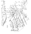
- each blank consists of portions 4, 5, 6, 7 respectively meant for the upright front wall, the bottom, the upright rear wall and the cover wall of the box to be folded and also, connected with the said portions, of portions 8, 9, 10, 11 for the upright side walls.
- the lowermost blank of the stack contained in the magazine is each time removed from the magazine and pulled into the mould cavity of the mould by means of a composite first conveyor including two vertical bars 18 which carry each at their top ends a suction head 19 provided with suction cups 20 and adapted to be connected to a suction pipe (not shown) and are attached to a block 17 which is mounted for reciprocation along stationary vertical guide rods 16.
- the suction heads 19 engage said blank on the lower side of the bottom portion 5 thereof and the mould cavity has a bottom area which corresponds with said bottom portion.
- the lower side of the blank is meant the side, which forms after the folding operation the outer surface of the box or trough.
- the side wall portions 8 and 10 thereof meet the far upwardly pointing folding members 12 and the high level folding members 15, whereby said side wall portions are set substantially upright in respect of the front wall portion 4 and the rear wall portion 6.
- the rear wall portion 6 and the cover wall portion 7 and the side wall portions 10 and 11 are bent upwards and set at an angle between 45° and 90° with the bottom portion 5 by the free ends of folding fingers 36 which will be discussed hereinafter.
- the front wall portion 4 with its already set side wall portions 8 is set upright by the less far upwardly pointing folding members 13 and a little later the side wall portions 9 are bent upright by the still lower folding members 14.
- the second conveyor comprises a block 24 mounted for reciprocation along stationary horizontal guide rods 23 and carrying a bar 25 provided with two suction cups 26 which are adapted to be connected to a suction conduit (not shown).
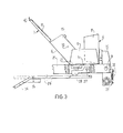
- the suction cups 26 are supported by an arm 28 which is swingably mounted on a shaft 27 and is held, during a portion of the active stroke (to the left) at the beginning thereof and during a portion of the inactive stroke (to the right) at the end thereof, up by a guide strip 29 not illustrated in Figure 2 but in Figure 3 to such an extent that the suction cups 26 are adapted to engage a box contained in the mould on the lower side of its bottom 5 and to continue to hold the box through the length of the mentioned portion at the beginning and at the end of the to and fro stroke, respectively, of the bar 25.
- the transport of the box out of the mould and along the supporting strips 22 is effected by a carrier member 30 provided at the end of the bar 25 and mounted for swinging about an axis 31.
- Said carrier member 30 is forced by a spring 32 into the active position shown in Figure 3 and held, during said transport, in said position by a roller 33 engaging the lower side of the guide strip 29.
- the left end portion 34 of the stationary guide strip 29 is adapted to tumble about an axis 35 and acts as a switch for the roller 33 of the carrier member 30 ( Figure 3). If, near the end of the active stroke of the bar 25, the roller 33 contacts the lower side of the left end portion 34 of the guide strip 29, said end portion is swung up by the roller 33, so that it forms an extension of the guide strip 29 and the roller 33 is permitted to pass under said end portion. As soon as said end portion 34 has been left by the roller 33, the portion 34 tumbles down again, that means into the oblique position shown in Figure 3, so that, during the inactive stroke of the bar 25 (to the right), the roller 33 runs up the end portion 34 and comes to roll on the upper side of the guide strip 29.
- the carrier member 30 is then swung in the horizontal position, so that, when moved during said stroke to its right-hand end position, it can pass under a next box arrived in the meantime in the mould cavity, without contacting said box.
- the carrier member is swung again by the spring 32 into the active position shown in Figure 3.
- suction cups 26 engage the bottom of the box near the edge between the bottom and the upright rear wall 6.
- the object thereof is to keep the bottom of the box flat, consequently, to keep said edge pressed on the supporting strips, when the rear wall portion 6 and the cover wall 7 together with its side wall portions 11 are folded during the horizontal transport of the box out of the mould.
- the protruding folding fingers 37 may be omitted and form each together with a set of two folding fingers 38 an outwardly bent catch plate.
- Glue is applied on the respective side wall portions by means of glue-guns, licking devices or other glue applying devices, which are omitted in the drawing for the sake of clarity.
- a marginal portion 40 is provided on the cover wall portion, said marginal portion being folded over and gluec to the front wall portion 4 by means of a folding plate 42 which for instance may be pneumatically tilted about an axis 41.
- the first and the second conveyor of the apparatus illustrated in Figures 1, 2 and 3 are driven synchronously by means of an endless chain 43 driven by a motor '75 (not shown in Figures 1, 2 and 3; see Figures 4, 5) and connected pivotally in a point 44 with one end of a link 45, of which the other end is pivotally secured to the block 24 of the second conveyor. If the chain 43 is driven in one direction, the second conveyor reciprocates between two end positions.
- the block 24 is also connected with the point 46 of a second endless chain 47 which is coupled with a third endless chain 50 through sprocket wheels 48 and 49.
- This third chain is attached in the point 51 to the block 17 of the first conveyor. Due to this coupling of the two conveyors the suction head 19 with its suction cups 20 will be moved upwardly to draw a blank 3 from the magazine 2, when the second conveyor moves to the left to remove a partially folded box out of the mould to complete the folding thereof during the rest of the horizontal transport and to discharge it, and vice versa.
- the apparatus illustrated in Figures 4, 5 and 6 differs mainly from the one shown in Figures 1, 2 and 3 in that the magazine 52 containing the blanks 3 is not positioned straight above the first conveyor 17, 18, 19, 20 but is found at some distance to the left from the place above said conveyor and a third conveyor 54 with suction cups 55 connected to a suction conduit is provided which is mounted for swinging about an axis 53, is adapted to engage each time the lowermost blank of the stack contained in the magazine on the lower side thereof and to place said blank onto two composite horizontal guide bars 56 for supporting the blank at two opposite edges and in marginal portions on the lower side thereof adjacent to said edges (Figure 6).
- the third conveyor 54, 55 is freely pivotable about the common shaft 53 of the sprocket wheels of the interconnected endless chains 47 and 58 and it is attached through a tail member 59 and a rod 60 to a block 61 which is also freely pivotable about the shaft 53.
- Said block 61 is provided with operating arms 64 and 65 adapted to be brought into the path of two carrier members 62 and 63 of the chain 47.
- the carrier members 57 are in the left-hand end position and a blank 3 is disposed onto the guide bars 56 by the third conveyor 54, 55.
- the carrier member 62 is also moved to the right, but the carrier member 63 is moved to the left ( Figure 6). In that case the carrier member 63 is passed through a recess 67 provided in the arm 65 and bridged by a weak leaf spring 66 without taking said arm along. During the return stroke of the chains 47 and 58 the carrier member 62 is moved to the left and the carrier member 63 is moved to the right (see the arrows 68, 69 in Figure 6).
- the carrier member 63 bumps against the leaf spring 66, so that the arms 65, 64 and the conveyor 54, 55 are pushed upwardly thereby and the suction cups 55 are forced against the lowermost blank 3 contained in the magazine 52.
- the arm 64 is swung into a position within the reach of the latter member (see the position of the arm 64 shown in dolted lines in Figure.5).
- the carrier member 63 can be moved whilst passing under the arm 65 to its end position shown in Figure 4.
- the carrier member 62 contacts the upwardly swung arm 64 the conveyor 54, 55, the blank sucked thereto and the arms 64, 65 are forced downwardly by the carrier member 62 and a next blank is disposed onto the guide bars 56.
- the load for the box may be disposed onto the bottom portion thereof.
- the box is filled with a single layer of bottles or tins 70.
- bottles or tins are supplied by a conveyor belt 71 and pushed by a pushing member 72 onto the blank lying in its place straight above the first conveyor ( Figures 4, 5).
- the pushing member 72 is attached to an endless chain 73 mounted for reciprocation between two end positions and passed over a sprocket wheel 74 which is fixed on the shaft of the sprocket wheels 48, 49 of the chains 47 and 50. Consequently, the pushing member is reciprocated synchronously with the four conveyors described hereinbefore.
- the diameters of the sprocket wheels 48, 49 and 74 define the ratio between the stroke of the first conveyor, the one of the pushing member and those of the second conveyor and the carrier members 57 of the fourth conveyor, whereas the ratio between the strokes of the two last mentioned conveyors is determined by the diameters of the sprocket wheels fixed on the shaft 53.
- the pushing member 72 will have to push each time a layer of articles which may be placed in advance on a sheet of board onto the layer or layers of articles already disposed on the blank, after the first conveyor 17, 18, 19, 20 has been lowered through the height of one layer.
- This requires between the conveyors and the pushing member the provision of a driving mechanism which drives the first conveyor stepwise downwardly, that means each time through the height of a layer of articles.
- a particular feature of the described embodiments of the apparatus according to the invention is, that one set of folding members 12, 13, 14, 15, 36, 37, 38, 39, walls of the magazine 2 or 52 and suction cups 20 with accessories of the first conveyor 17, 18, 19, 20, and also one supporting strip 22 and one guide bar 56 are attached to a stationary part whereas the other set of corresponding members, the other supporting strip 22 and the other guide bar 56 are attached to a movable part of the apparatus mounted for adjustment, for instance by means of a serewed rod with a hand wheel, in a direction transverse to the direction of movement of the second conveyor and parallel to the plane of the path thereof. Furthermore, the folding members 15 and the carrier members 57 of the chains 58 are mounted for adjustment in the direction of movement of the second conveyor and the folding fingers 36 are adjustable in the direction of movement of the first conveyor.
- the stroke of the pushing member 72 can be adapted by selection of the d -meter of the sprocket wheel 74.
- the third conveyor 54, 55 may be slidably mounted on the shaft for its adjustment. It has appeared, that mostly it is not necessary that one of the chains 58 with its carrier member 57 is also mounted for adjustment in the transverse direction referred to.
Landscapes
- Making Paper Articles (AREA)
Applications Claiming Priority (2)
| Application Number | Priority Date | Filing Date | Title |
|---|---|---|---|
| NL8400856A NL8400856A (nl) | 1984-03-16 | 1984-03-16 | Inrichting voor het tot een doos of een bak vouwen van een plano. |
| NL8400856 | 1984-03-16 |
Publications (1)
| Publication Number | Publication Date |
|---|---|
| EP0155733A1 true EP0155733A1 (de) | 1985-09-25 |
Family
ID=19843661
Family Applications (1)
| Application Number | Title | Priority Date | Filing Date |
|---|---|---|---|
| EP85200376A Withdrawn EP0155733A1 (de) | 1984-03-16 | 1985-03-14 | Apparat zum Falten einer Schachtel oder eines Troges aus einem Zuschnitt |
Country Status (5)
| Country | Link |
|---|---|
| US (1) | US4614511A (de) |
| EP (1) | EP0155733A1 (de) |
| JP (1) | JPS60212337A (de) |
| AU (1) | AU3962285A (de) |
| NL (1) | NL8400856A (de) |
Cited By (1)
| Publication number | Priority date | Publication date | Assignee | Title |
|---|---|---|---|---|
| EP2594440A1 (de) | 2011-11-17 | 2013-05-22 | Batz, S.Coop. | Pedal für Kraftfahrzeuge mit einem Sicherheitsmechanismus für Frontalzusammenstöße |
Families Citing this family (9)
| Publication number | Priority date | Publication date | Assignee | Title |
|---|---|---|---|---|
| SE457634B (sv) * | 1986-04-18 | 1989-01-16 | Tetra Pak Ab | Anordning foer resning av foerpackningsbehaallaraemnen |
| US5184998A (en) * | 1991-04-08 | 1993-02-09 | Volk Packaging Corporation | Corrugated cardboard or chipboard carton forming machine |
| FI97355C (fi) * | 1995-01-04 | 1996-12-10 | Jopamac Ab Oy | Laitteisto pinkassa olevan paperitavaran pakkaamiseksi |
| US6070396A (en) * | 1996-11-27 | 2000-06-06 | Specialty Machinery, Inc. | Carton folding apparatus |
| CN102581683B (zh) * | 2012-03-09 | 2014-10-01 | 昆山艾博机器人系统工程有限公司 | 箱体外壳安装输送装置 |
| CN109625437B (zh) * | 2018-12-27 | 2024-01-30 | 重庆市灵龙自动化设备有限公司 | 用于塑型及定型硬质外包装的传送线 |
| CN109625440B (zh) * | 2018-12-27 | 2023-12-08 | 重庆市灵龙自动化设备有限公司 | 具有塑型及定型功能的传送装置 |
| CN112172238A (zh) * | 2020-09-11 | 2021-01-05 | 上海嘉亿机械有限公司 | 一种纸箱折叠成型系统 |
| CN116922861B (zh) * | 2023-09-19 | 2023-11-17 | 汇源印刷包装科技(天津)股份有限公司 | 一种硬性包装盒的印刷加工设备 |
Citations (8)
| Publication number | Priority date | Publication date | Assignee | Title |
|---|---|---|---|---|
| US2723603A (en) * | 1951-03-23 | 1955-11-15 | Int Paper Box Machine Co | Formless paper box machine |
| US2743651A (en) * | 1953-08-31 | 1956-05-01 | Fibreboard Products Inc | Carton setting up machine |
| US2820403A (en) * | 1954-04-14 | 1958-01-21 | Ohio Boxboard Co | Carton machine |
| US3046849A (en) * | 1961-05-15 | 1962-07-31 | Continental Folding Paper Box | Box forming machines |
| US3065679A (en) * | 1959-12-15 | 1962-11-27 | Ernest C Clement | Carton forming apparatus |
| US3218940A (en) * | 1963-09-26 | 1965-11-23 | Pearson Co R A | Carton setting up machine |
| DE2106465A1 (de) * | 1970-02-11 | 1971-08-26 | Stone Container Corp , Chicago, 111 (VStA) | Verfahren und Vorrichtung zum Verpacken von Gegenstanden in Kartons |
| DE2008313A1 (de) * | 1970-02-23 | 1971-09-02 | Stone Container Corp , Chicago, IU (V St A ) | Verpackungsmaschine |
Family Cites Families (4)
| Publication number | Priority date | Publication date | Assignee | Title |
|---|---|---|---|---|
| US3543469A (en) * | 1966-04-25 | 1970-12-01 | Huntingdon Ind Inc | Packaging apparatus |
| US3533333A (en) * | 1968-04-01 | 1970-10-13 | Emhart Corp | Machine for erecting cases |
| US4149452A (en) * | 1977-05-04 | 1979-04-17 | Talarico Lawrence J | Folding and packaging machine |
| US4206691A (en) * | 1978-05-02 | 1980-06-10 | Iowa Beef Processors, Inc. | Box forming apparatus |
-
1984
- 1984-03-16 NL NL8400856A patent/NL8400856A/nl not_active Application Discontinuation
-
1985
- 1985-03-06 US US06/708,952 patent/US4614511A/en not_active Expired - Fee Related
- 1985-03-07 AU AU39622/85A patent/AU3962285A/en not_active Abandoned
- 1985-03-14 EP EP85200376A patent/EP0155733A1/de not_active Withdrawn
- 1985-03-16 JP JP60053205A patent/JPS60212337A/ja active Pending
Patent Citations (8)
| Publication number | Priority date | Publication date | Assignee | Title |
|---|---|---|---|---|
| US2723603A (en) * | 1951-03-23 | 1955-11-15 | Int Paper Box Machine Co | Formless paper box machine |
| US2743651A (en) * | 1953-08-31 | 1956-05-01 | Fibreboard Products Inc | Carton setting up machine |
| US2820403A (en) * | 1954-04-14 | 1958-01-21 | Ohio Boxboard Co | Carton machine |
| US3065679A (en) * | 1959-12-15 | 1962-11-27 | Ernest C Clement | Carton forming apparatus |
| US3046849A (en) * | 1961-05-15 | 1962-07-31 | Continental Folding Paper Box | Box forming machines |
| US3218940A (en) * | 1963-09-26 | 1965-11-23 | Pearson Co R A | Carton setting up machine |
| DE2106465A1 (de) * | 1970-02-11 | 1971-08-26 | Stone Container Corp , Chicago, 111 (VStA) | Verfahren und Vorrichtung zum Verpacken von Gegenstanden in Kartons |
| DE2008313A1 (de) * | 1970-02-23 | 1971-09-02 | Stone Container Corp , Chicago, IU (V St A ) | Verpackungsmaschine |
Cited By (1)
| Publication number | Priority date | Publication date | Assignee | Title |
|---|---|---|---|---|
| EP2594440A1 (de) | 2011-11-17 | 2013-05-22 | Batz, S.Coop. | Pedal für Kraftfahrzeuge mit einem Sicherheitsmechanismus für Frontalzusammenstöße |
Also Published As
| Publication number | Publication date |
|---|---|
| JPS60212337A (ja) | 1985-10-24 |
| NL8400856A (nl) | 1985-10-16 |
| AU3962285A (en) | 1985-09-19 |
| US4614511A (en) | 1986-09-30 |
Similar Documents
| Publication | Publication Date | Title |
|---|---|---|
| US5298008A (en) | Case opening apparatus | |
| EP0011965B1 (de) | Maschine zum Aufrichten von korbartigen Faltschachteln | |
| US4614511A (en) | Apparatus for folding a box or trough from a blank | |
| US5024045A (en) | Panel packaging system | |
| US4095721A (en) | Berry tray denesting and berry packaging | |
| US5656007A (en) | Apparatus for constructing multi-piece cartons | |
| US3482372A (en) | Method and apparatus for packaging containers | |
| US4023471A (en) | Apparatus for assembling a carton | |
| JPS63503375A (ja) | 物品キャリヤ・スリーブを送りつつ開く装置 | |
| US4941309A (en) | Panel packaging system | |
| JPH0223407B2 (de) | ||
| JPS6238205B2 (de) | ||
| US3379346A (en) | Dispensing apparatus for hollow nested articles | |
| US4499704A (en) | Corrugated box forming, loading and sealing machine | |
| GB2065585A (en) | Packaging apparatus | |
| EP0252015B1 (de) | Automatische Maschine zum Formen von Kartons mit vorstehendem Deckel und vorstehendem Boden | |
| US3134309A (en) | Apparatus for erecting packing cases | |
| GB2073128A (en) | Tying machine | |
| US4787881A (en) | Arrangement for the raising of packing container blanks | |
| AU719586B2 (en) | High-speed blank set-up apparatus and methods | |
| US2848856A (en) | Lid forming machine | |
| CA1288990C (en) | Packaging machine with direct blank setup | |
| US3388640A (en) | Method and apparatus for inserting a liner into a carton | |
| US3015256A (en) | Machine for forming cartons | |
| US2882657A (en) | Banding apparatus and method |
Legal Events
| Date | Code | Title | Description |
|---|---|---|---|
| PUAI | Public reference made under article 153(3) epc to a published international application that has entered the european phase |
Free format text: ORIGINAL CODE: 0009012 |
|
| AK | Designated contracting states |
Designated state(s): AT BE CH DE FR GB IT LI LU NL SE |
|
| STAA | Information on the status of an ep patent application or granted ep patent |
Free format text: STATUS: THE APPLICATION IS DEEMED TO BE WITHDRAWN |
|
| 18D | Application deemed to be withdrawn |
Effective date: 19860526 |