EP0155338A1 - Attelage à hauteur réglable pour remorque - Google Patents
Attelage à hauteur réglable pour remorque Download PDFInfo
- Publication number
- EP0155338A1 EP0155338A1 EP84103443A EP84103443A EP0155338A1 EP 0155338 A1 EP0155338 A1 EP 0155338A1 EP 84103443 A EP84103443 A EP 84103443A EP 84103443 A EP84103443 A EP 84103443A EP 0155338 A1 EP0155338 A1 EP 0155338A1
- Authority
- EP
- European Patent Office
- Prior art keywords
- coupling jaw
- swivel plate
- coupling
- jaw carrier
- bolts
- Prior art date
- Legal status (The legal status is an assumption and is not a legal conclusion. Google has not performed a legal analysis and makes no representation as to the accuracy of the status listed.)
- Granted
Links
Images


Classifications
-
- B—PERFORMING OPERATIONS; TRANSPORTING
- B60—VEHICLES IN GENERAL
- B60D—VEHICLE CONNECTIONS
- B60D1/00—Traction couplings; Hitches; Draw-gear; Towing devices
- B60D1/24—Traction couplings; Hitches; Draw-gear; Towing devices characterised by arrangements for particular functions
- B60D1/42—Traction couplings; Hitches; Draw-gear; Towing devices characterised by arrangements for particular functions for being adjustable
- B60D1/46—Traction couplings; Hitches; Draw-gear; Towing devices characterised by arrangements for particular functions for being adjustable vertically
Definitions
- the invention relates to a height-adjustable trailer hitch according to the preamble of claim 1.
- a trailer hitch of this type is described in DE-PS 29 10 164.
- two bolts in the form of bolts are guided in alignment in the coupling jaw carrier and are biased against each other into the respective locking position by a compression spring arranged between them.
- the essentially circular swivel plate on the coupling jaw carrier is mounted so that it can swivel around its center.
- Both bolts are each connected to the swivel plate by an intermediate lever located between the swivel plate and the associated bolt. At one end of each intermediate lever, a pin is attached, which is inserted into a hole in the pivot plate.
- Another pin penetrates the other end of the intermediate lever and the associated bolt, resulting in a toggle lever construction and in the locking position of the pivot plate and bolt, the hinge axes of the connections between the pivot plate and the intermediate levers on the one hand and the connections between the latter and the bolts on the other on a straight line lie.
- the pivot point of the swivel plate also lies on this straight line.
- the two cones; that connect the intermediate levers with the bolts are each guided in two guide slots in the coupling jaw.
- the guide slots are designed as horizontal elongated holes which only limit the stroke of the bolts and are intended to prevent the bolts from falling out if the intermediate lever is unintentionally loosened from the swivel plate.
- a handle is attached to an upwardly projecting approach of the swivel plate, by means of which the swivel plate can be swiveled between its locked position and its unlocked position and which at the same time serves to hold the entire arrangement in the height adjustment.
- the attachment of the swivel plate connected to the handle is penetrated by a pin which, in conjunction with a tab pivotally attached to the coupling jaw carrier, serves to lock the swivel plate in its locked position. Only when the tab has been swiveled out of the movement path of the pin can the swivel plate be brought into the unlocked position using the handle.
- a compression spring acts on each of the guide rails on the one hand and on the coupling jaw carrier, on the other, to counteract the weight of the coupling jaw carrier with coupling jaw and thus to facilitate height adjustment.
- the object of the invention is to provide a height-adjustable trailer coupling of the type specified, which manages with few elements, is reliable and has a short overall length.
- a short overall length is advantageous if, for example in an agricultural tractor, additional units are to be attached and the trailer coupling does not interfere due to its short overall length and therefore does not have to be removed beforehand.
- the short overall length is achieved in that the bolts and the mechanism serving to adjust them are not arranged one behind the other but essentially in one plane.
- the coupling between the bolts and the swivel plate takes place through a direct engagement between these two parts, without the need for an intermediate lever.
- the swivel plate can dip into a corresponding groove in the respective bolt. Both parts are then held together by means of a pin which passes through aligned holes in the groove walls and a guide slot in the swivel plate.
- the guide slots serve and are shaped accordingly to convert the pivoting movement of the pivoting plate into pushing movements of the bolts between their locking position and their unlocking position.
- the shape of the guide slot makes it very easy to achieve certain characteristics, for example a progressive movement in the sense that the distance covered by the bolts from the locking position per pivoting angle unit increases with increasing pivoting angle. This corresponds to an initial force transmission which facilitates handling when the lock is released.
- the engagement between the swivel plate and the latches can, as a further example, also take place in that the latches are immersed in a circumferential groove of the swivel plate.
- the guide slots should preferably be provided in both groove walls.
- the pivoting of the swivel plate can be carried out in a manner known per se by means of a handle which is attached to an attachment of the swivel plate. It is particularly advantageous, in turn, to design this handle so that it can be pivoted between a rest position and an operating position, and to provide that in its rest position it can be adjusted by a positive connection between the coupling jaw carrier or a part that is rigid with respect to it on the one hand and the swivel plate on the other hand from its locking position prevented.
- This type of locking of the swivel plate by means of the handle on the one hand increases safety and on the other hand allows complete one-hand operation of the height-adjustable coupling.
- the handle is pivoted from a rest position, in which it contributes as little as possible to the overall height of the arrangement, into an operating position in which it enables the coupling jaw carrier and coupling to be held comfortably and the pivoting plate to be pivoted.
- an operating position in which it enables the coupling jaw carrier and coupling to be held comfortably and the pivoting plate to be pivoted.
- the swivel plate is designed as a cam, the outer edge of which in the region of the guide slots, the swivel plate, that is in the area which comes into engagement with the bolts, runs essentially parallel to the guide slots and forms safety stops for the bolts.
- the guide slots in the swivel plate are preferably designed so that the part of the guide slots on which the pins rest in the locking position of the swivel plate is perpendicular to the direction of movement of the latches and that these parts of the guide slots are on a common line passing through the pivot point of the swivel plate lie. This ensures that a force acting on the bolt and pushing it out of its locking position is not converted into a torque loading the swivel plate.
- the coupling jaw carrier 2 is in turn carried by a trailer bracket 19 which is fastened to the vehicle by means of screws 25, generally on the transmission block 51.
- the trailer bracket 19 comprises two side plates 19a and 19b, each of which carries a guide rail 17 at its end facing away from the vehicle, in the guide grooves of which the coupling jaw carrier 2 is guided in a vertically movable manner, as can best be seen from FIG. 2. With the help of threaded rods 20 and nuts 21, a side stabilization of the trailer bracket and at the same time the adjustment of the distance between the two guide rails 17 is effected.
- a tension spring 22 is arranged on the side of each of the two guide rails 17 between the upper end of the guide rail and the coupling jaw carrier.
- a pin 23a holds the upper end of the tension spring 22 on the guide rail 17, while a pin 23b holds the lower end of the tension spring on the coupling jaw carrier 2.
- the guide rails are provided with recesses 17a, which are shown in FIG. 1 as bores in the base of the guide grooves of the guide rails 17.
- the coupling jaw carrier 2 has latches 4 which engage in these recesses 17a and thereby lock the coupling jaw carrier at a respectively selected height. If a different height position of the coupling is to be set, the bolts 4 must be withdrawn from the recesses 17a, the coupling jaw carrier brought to the new height position and the bolts 4 pushed again into the corresponding recesses 17a.
- FIG. 3 In the top view of FIG. 3, in which a part of the handle 10 still to be explained, for the sake of clarity. is omitted, one can see the offset ends 2a of the coupling jaw carrier 2, which plunge into the guide grooves of the guide rails when the coupling is installed.
- the latches 4 shown here in the locked position protrude from them and interact with the described recesses 17a of the guide rails.
- Two bolts 4 are preferably guided on opposite sides in mutually aligned bores in the coupling jaw carrier 2. At their inner end, the bolts 4 have a groove 4a into which a pivot plate 6 is immersed, which is rotatably mounted on a bearing pin 5 in the coupling jaw carrier 2.
- the bearing pin 5 is carried on the one hand by a bearing washer 3 and on the other hand by an end cover 15.
- the bearing plate 3 is placed in a recess provided for this purpose in the interior of the coupling jaw carrier 2, while the end cover 15 is fastened to the coupling jaw carrier 2 with the aid of screws 16.
- pins 13 With the help of pins 13, the two bolts 4 and the swivel plate 6 are held in engagement with one another.
- the pins 13 pass through corresponding bores in the bolts 4 and each have a guide slot 6a in the swivel plate 6 (cf. also FIGS. 5 and 6).
- the swivel plate 6 is provided with a shoulder 6b (FIG. 4) which protrudes from the coupling mouth carrier 2 at the top and carries the handle 10 already mentioned. With the aid of the handle 10, the swivel plate 6 can be pivoted about the bearing pin 5 between two end positions, namely a locking position and an unlocking position.
- the guide slots 6a are designed so that the bolts 4 are in turn in the locking position of the swivel plate in a locking position, that is to say protrude relatively far from the coupling jaw carrier 2.
- the bolts 4 in the unlocking position of the swivel plate 6 are retracted so far into the coupling jaw carrier 2 that the latter can be adjusted in height in the guide rails 17 of the trailer bracket 19.
- the torsion spring 14 inserted on the bearing pin 5 is placed with its one bent end around the shoulder 10 of the pivot plate 6 carrying the handle, while its other end is inserted through a bore 15a in a bulge of the end cover 15.
- the handle 10 is bow-shaped, essentially in the form of a U and is rotatably supported with its one leg at the end of the extension 6b of the swivel plate 6.
- This end of the extension 6b is fork-shaped with two bearing flanges 7, through the aligned holes of which the handle 10 is inserted.
- a locking cam 9 is arranged on the handle 10 and connected to it in a rotationally fixed manner by means of an adapter sleeve 11.
- the shape of the locking cam 9 can be seen particularly well from the side view of FIG. 4.
- a torsion spring 8 biases the handle 10 against the shoulder 6b of the swivel plate 6 into a rest position (counterclockwise in FIG.
- the locking cam 9 In the rest position, the locking cam 9 is supported on the shoulder 6b by a clamping sleeve 12 passing through it essentially parallel to the axis of rotation of the handle 10. In this rest position, the handle 10 lies essentially in a horizontal plane, at least in such a way that it contributes as little as possible to the overall height of the arrangement. In the rest position of the handle 10, part of the locking cam 9 is immersed in a recess 15b at the edge of the end cover 15, whereby pivoting of the pivot plate 6 is prevented. In the operating position of the handle 10, the locking cam 9 is supported on the extension 6b by means of knobs 44 extending from it on both sides (see FIG. 6).
- the handle 10 must first be folded up from its rest position shown in FIG. 5 into the operating position shown in FIG. 6, in which the locking cam 9 disengages the end cover 15 is.
- the swivel plate 6 can then be pivoted from the locking position shown in FIG. 5 into the unlocking position shown in FIG. 6 against the force of the torsion spring 14 by means of the handle. Due to the described guidance of the pins 13 connected to the bolts 4 in the guide slots 6a, the bolts 4 are moved into their unlocked position in the coupling jaw carrier 2 during this pivoting of the swivel plate 6 withdrawn.
- the clutch now hangs in the hand of the operator, the weight being largely compensated for by the tension springs 22 mentioned at the outset.
- the clutch can now be raised or lowered to a new altitude.
- the opposite procedure is followed; that is, first the pivot plate 6 is pivoted back into the locking position by means of the handle 10 and then the handle 10 itself is folded down into its rest position.
- Both the folding of the handle for the purpose of locking or unlocking the pivot plate 6, as well as the pivoting of the pivot plate 6 and the raising or lowering of the entire coupling is carried out by corresponding actuation of one and the same actuating element, namely the handle 10, so that with the Invention a real one-handed operation is created.
- the handle 10 is pretensioned into its rest position by the torsion spring 8, whereby at the same time the individual parts are braced against one another.
- the swivel plate 6 is designed as a cam, as shown in the drawings, the outer edge of which has a course such that, in the locked position of the swivel plate 6, there is only a relatively small distance between the outer edge 41 and a stop surface 42 of the latch 4 .
- the outer edge preferably runs approximately parallel to the guide slots 6a. If the bolts are provided with a groove 4a as shown in FIG. 3, then the groove base forms the stop surface 42. Should a pin 13 break in such a configuration and thereby release the guiding engagement between bolt 4 and swivel plate 6, it would still be ensures that the associated bolt can not leave its locking position unintentionally, as long as the Swivel plate is in its locked position.
- the respective end 40 of the guide slots 6a extends, at least on the radially inner side, perpendicular to the direction of movement of the bolt 4.
- these ends 40 or the center lines of the pins 13 lie together with the pivot point of the pivot plate 6 on a straight line, so that an inward pressure on the bolt 4 in the locked position does not result in torque on the swivel plate 6.
- the invention creates an extremely compact arrangement of very short overall length, which requires few individual parts and is particularly easy to assemble.
- the swivel plate 6 with the handle 10 can be preassembled as a structural unit. When assembling the bearing disc 3 is then placed in the coupling jaw 2. Then the pre-assembled swivel plate 6 is inserted with the bearing pin 5. Before or after the bars 4 are inserted. Then the pins 13 are inserted and the torsion spring 14 is anchored to the swivel plate 6. Finally, the other end of the torsion spring 14 is inserted through the aforementioned hole 15a in the end cover 15 and the end cover under tension of the spring in it Mounting position rotated to then be fastened by means of the screws 16.
- the engagement between bolt 4 and swivel plate 6 can be shown differently than in FIG. 3.
- a groove 4a provided approximately in the central plane
- a step-like recess can be provided on one edge of the latch 4, in which the swivel plate 6 would engage in a similar manner.
- the swivel plate 6 could be provided with a groove and in turn, for example, encompass a flattened part of the bolt.
- the coupling jaw 1 is rotatably mounted in the coupling jaw carrier 2.
- a lubricating nipple 50 is used to lubricate this bearing, by means of which grease can be pressed between the moving parts of this bearing.
- the coupling jaw carrier 2 is now preferably designed such that the grease emerging at the end of the coupling jaw bearing facing away from the grease nipple enters a recess 46 and, via this recess, reaches, among other things, the point of engagement between the bolts 4 and the swivel plate 6 and in particular in the region of their guide slots 6a. In this way, the locking mechanism described can also be lubricated when the clutch is lubricated.
- an opening 48 is formed (see FIGS. 4, 5 and 6) through which water which has penetrated can run off.
- the clutch jaw carrier 2 is displaceable in the guide rails 17 past the PTO shaft 26 (FIG. 1) and can also be locked below the PTO shaft, so that the clutch is used accordingly when the PTO shaft 26 is used can be moved deep and does not interfere with the PTO operation. Even in its lowest position, the coupling can be used for hanging.
- a stop 18 prevents the coupling jaw carrier 2 from sliding out of the guide rails.
- a PTO protection 24 only indicated in the drawings is attached so that it can be easily removed when the clutch is to be adjusted under the PTO.
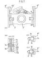
- FIG. 7a shows a view from the front, the coupling mouth not being shown.
- FIG. 7b shows a partial top view of the arrangement from FIG. 7a to explain the locking position, while FIG. 7c is a corresponding view in the unlocking position.
- Figure 7d is a sectional view taken along section line A-A in Figure 7a.
- the recesses 17a are formed in the bottom of the guide groove of the guide rails 17, that is to say they extend in the direction of movement of the bolts 4. In order to engage these recesses, the bolts 4 protrude beyond the lateral ends of the coupling jaw carrier 2 in their locking position.
- the recesses 17a ' are formed in the side walls of the guide rails 17', between which the set ends 2a of the coupling jaw carrier 2 'are guided. So that this guidance is not impaired, the height of these recesses 17a 'is small in relation to the height of the stepped ends 2a of the coupling jaw carrier 2'.
- the bolts 4 ' have lateral projections 34 which project outwards on both sides through corresponding openings in the coupling jaw support 2', as can be clearly seen from FIGS. 7b to 7d.
- the latches 4 ' In the locked position, the latches 4 'are supported symmetrically and over a large area on bottoms 35 of the recesses 17a with respect to the stepped ends 2a of the coupling jaw carrier 2' and, on the other hand, rest on guide surfaces 30 of the coupling jaw carrier 2 '. The occurring vertical loads are thus transmitted to two surfaces of the guide rails 17 'via the coupling jaw carrier 2' and the bolts 4 '.
- the side lugs 34 of the bolts 4 ' In the unlocked position, the side lugs 34 of the bolts 4 'are pulled out of the recesses 17a' so that they are at a distance from the guide rails 17 ', as can be seen from FIG. 7c.
Landscapes
- Engineering & Computer Science (AREA)
- Transportation (AREA)
- Mechanical Engineering (AREA)
- Agricultural Machines (AREA)
- Vehicle Body Suspensions (AREA)
- Vehicle Cleaning, Maintenance, Repair, Refitting, And Outriggers (AREA)
- Regulating Braking Force (AREA)
- Fittings On The Vehicle Exterior For Carrying Loads, And Devices For Holding Or Mounting Articles (AREA)
Priority Applications (3)
| Application Number | Priority Date | Filing Date | Title |
|---|---|---|---|
| DE8484103443T DE3461152D1 (en) | 1984-03-28 | 1984-03-28 | Trailer hitch adjustable in height |
| AT84103443T ATE23297T1 (de) | 1984-03-28 | 1984-03-28 | Hoehenverstellbare anhaengerkupplung. |
| EP84103443A EP0155338B1 (fr) | 1984-03-28 | 1984-03-28 | Attelage à hauteur réglable pour remorque |
Applications Claiming Priority (1)
| Application Number | Priority Date | Filing Date | Title |
|---|---|---|---|
| EP84103443A EP0155338B1 (fr) | 1984-03-28 | 1984-03-28 | Attelage à hauteur réglable pour remorque |
Publications (2)
| Publication Number | Publication Date |
|---|---|
| EP0155338A1 true EP0155338A1 (fr) | 1985-09-25 |
| EP0155338B1 EP0155338B1 (fr) | 1986-11-05 |
Family
ID=8191851
Family Applications (1)
| Application Number | Title | Priority Date | Filing Date |
|---|---|---|---|
| EP84103443A Expired EP0155338B1 (fr) | 1984-03-28 | 1984-03-28 | Attelage à hauteur réglable pour remorque |
Country Status (3)
| Country | Link |
|---|---|
| EP (1) | EP0155338B1 (fr) |
| AT (1) | ATE23297T1 (fr) |
| DE (1) | DE3461152D1 (fr) |
Cited By (16)
| Publication number | Priority date | Publication date | Assignee | Title |
|---|---|---|---|---|
| EP0215443A2 (fr) * | 1985-09-17 | 1987-03-25 | Deere & Company | Cadre de support pour un attelage de remorque |
| GB2185723B (en) * | 1986-01-28 | 1989-12-06 | C P Witter Limited | Improvements in and relating to tow bars for vehicles |
| EP0401404A1 (fr) * | 1989-06-07 | 1990-12-12 | ROCKINGER Spezialfabrik für Anhängerkupplungen GmbH & Co. | Dispositif d'attelage réglable en hauteur |
| DE4012586C1 (en) * | 1990-04-20 | 1991-06-13 | Jean Walterscheid Gmbh, 5204 Lohmar, De | Height-adjustable agricultural trailer coupling - has actuating shaft, protruding coaxially into guide bush, coupled to guide plates |
| EP0446598A1 (fr) * | 1990-03-07 | 1991-09-18 | Georg Cramer | Attelage de remorquage, en particulier pour tracteur ou similaire avec prise de force arrière |
| DE4222342A1 (de) * | 1992-07-08 | 1994-01-13 | Hans Sauermann | Vorrichtung zum Halten einer Anhänge-Kupplungs-Tragplatte |
| AT1287U1 (de) * | 1995-04-05 | 1997-02-25 | Scharmueller Josef Ing | Anhängevorrichtung für zugfahrzeuge |
| EP0842595A2 (fr) * | 1996-11-07 | 1998-05-20 | CBM S.p.A. | Structure protectrice pour prise de force de véhicule agricole |
| EP0843956A1 (fr) * | 1996-11-15 | 1998-05-27 | Costruzioni Meccaniche G. Grassi di Luigi Grassi & C. S.n.c. | Dispositif d'accouplement pour tracteur ou similaire |
| EP1312491A1 (fr) * | 2001-11-16 | 2003-05-21 | Costruzioni Meccaniche G. Grassi & C. S.n.c. | Dispositif d'accouplement pour tracteur ou similaire |
| EP1386761A1 (fr) | 2002-07-30 | 2004-02-04 | Rockinger GmbH | Attelage à hauteur réglable pour remorque |
| DE10304978A1 (de) * | 2003-02-07 | 2004-08-19 | Deere & Company, Moline | Anhängevorrichtung für ein landwirtschaftliches oder industrielles Arbeitsfahrzeug |
| AT412630B (de) * | 2003-02-12 | 2005-05-25 | Josef Ing Scharmueller | Kupplungsvorrichtung und verfahren zum schliessen einer kupplungsvorrichtung |
| EP1688277A1 (fr) * | 2005-02-04 | 2006-08-09 | CBM S.p.A. | Coulisseau pour crochet de remorque pour véhicules |
| EP1987967A1 (fr) * | 2007-04-30 | 2008-11-05 | ARIES S.r.l. | Crochet de dépannage coulissant pour machines agricoles |
| EP2527170A1 (fr) | 2011-05-26 | 2012-11-28 | Rheinmetall MAN Military Vehicles GmbH | Attelage réglable en hauteur, en particulier pour véhicules utilitaires |
Citations (9)
| Publication number | Priority date | Publication date | Assignee | Title |
|---|---|---|---|---|
| US1566831A (en) * | 1922-09-16 | 1925-12-22 | Highway Trailer Co | Adjustable drawbar |
| CH352912A (de) * | 1956-01-02 | 1961-03-15 | Ruediger Dipl Ing Albrecht | Abschleppstange |
| DE1169794B (de) * | 1959-02-26 | 1964-05-06 | Auto Union Gmbh | Baskuelverschluss fuer Kraftfahrzeugschiebedaecher |
| FR1439226A (fr) * | 1965-04-08 | 1966-05-20 | Renault | Toit coulissant de véhicule avec dispositif de manoeuvre et de blocage |
| US3865406A (en) * | 1974-05-31 | 1975-02-11 | Truck Specialist Inc | Quick change hitch for trailer or mobile homes |
| DE2852773A1 (de) * | 1978-12-06 | 1980-06-12 | Rockinger Spezial Fab Joh | Vorrichtung zur befestigung einer anhaengekupplung an landwirtschaftlichen fahrzeugen |
| EP0016317A1 (fr) * | 1979-03-15 | 1980-10-01 | Xaver Fendt & Co. | Attelage réglabe en hanteur pour remorque |
| DE3122116A1 (de) * | 1981-06-04 | 1982-12-23 | Cramer-Kupplung GmbH & Co KG, 4300 Essen | "anhaengerkupplung, insbesondere fuer zugmaschinen" |
| EP0095443A1 (fr) * | 1982-05-26 | 1983-11-30 | Stillhart, Peter | Dispositif d'attelage |
-
1984
- 1984-03-28 AT AT84103443T patent/ATE23297T1/de not_active IP Right Cessation
- 1984-03-28 EP EP84103443A patent/EP0155338B1/fr not_active Expired
- 1984-03-28 DE DE8484103443T patent/DE3461152D1/de not_active Expired
Patent Citations (9)
| Publication number | Priority date | Publication date | Assignee | Title |
|---|---|---|---|---|
| US1566831A (en) * | 1922-09-16 | 1925-12-22 | Highway Trailer Co | Adjustable drawbar |
| CH352912A (de) * | 1956-01-02 | 1961-03-15 | Ruediger Dipl Ing Albrecht | Abschleppstange |
| DE1169794B (de) * | 1959-02-26 | 1964-05-06 | Auto Union Gmbh | Baskuelverschluss fuer Kraftfahrzeugschiebedaecher |
| FR1439226A (fr) * | 1965-04-08 | 1966-05-20 | Renault | Toit coulissant de véhicule avec dispositif de manoeuvre et de blocage |
| US3865406A (en) * | 1974-05-31 | 1975-02-11 | Truck Specialist Inc | Quick change hitch for trailer or mobile homes |
| DE2852773A1 (de) * | 1978-12-06 | 1980-06-12 | Rockinger Spezial Fab Joh | Vorrichtung zur befestigung einer anhaengekupplung an landwirtschaftlichen fahrzeugen |
| EP0016317A1 (fr) * | 1979-03-15 | 1980-10-01 | Xaver Fendt & Co. | Attelage réglabe en hanteur pour remorque |
| DE3122116A1 (de) * | 1981-06-04 | 1982-12-23 | Cramer-Kupplung GmbH & Co KG, 4300 Essen | "anhaengerkupplung, insbesondere fuer zugmaschinen" |
| EP0095443A1 (fr) * | 1982-05-26 | 1983-11-30 | Stillhart, Peter | Dispositif d'attelage |
Cited By (22)
| Publication number | Priority date | Publication date | Assignee | Title |
|---|---|---|---|---|
| EP0215443A3 (en) * | 1985-09-17 | 1988-04-20 | Deere & Company | Retention frame for a trailer coupling |
| EP0215443A2 (fr) * | 1985-09-17 | 1987-03-25 | Deere & Company | Cadre de support pour un attelage de remorque |
| GB2185723B (en) * | 1986-01-28 | 1989-12-06 | C P Witter Limited | Improvements in and relating to tow bars for vehicles |
| EP0401404A1 (fr) * | 1989-06-07 | 1990-12-12 | ROCKINGER Spezialfabrik für Anhängerkupplungen GmbH & Co. | Dispositif d'attelage réglable en hauteur |
| EP0446598A1 (fr) * | 1990-03-07 | 1991-09-18 | Georg Cramer | Attelage de remorquage, en particulier pour tracteur ou similaire avec prise de force arrière |
| DE4012586C1 (en) * | 1990-04-20 | 1991-06-13 | Jean Walterscheid Gmbh, 5204 Lohmar, De | Height-adjustable agricultural trailer coupling - has actuating shaft, protruding coaxially into guide bush, coupled to guide plates |
| DE4222342A1 (de) * | 1992-07-08 | 1994-01-13 | Hans Sauermann | Vorrichtung zum Halten einer Anhänge-Kupplungs-Tragplatte |
| DE4222342C2 (de) * | 1992-07-08 | 1998-02-19 | Hans Sauermann | Vorrichtung zum Halten einer Anhänge-Kupplungs-Tragplatte |
| AT1287U1 (de) * | 1995-04-05 | 1997-02-25 | Scharmueller Josef Ing | Anhängevorrichtung für zugfahrzeuge |
| EP0842595A3 (fr) * | 1996-11-07 | 1998-11-04 | CBM S.p.A. | Structure protectrice pour prise de force de véhicule agricole |
| EP0842595A2 (fr) * | 1996-11-07 | 1998-05-20 | CBM S.p.A. | Structure protectrice pour prise de force de véhicule agricole |
| EP0843956A1 (fr) * | 1996-11-15 | 1998-05-27 | Costruzioni Meccaniche G. Grassi di Luigi Grassi & C. S.n.c. | Dispositif d'accouplement pour tracteur ou similaire |
| EP1312491A1 (fr) * | 2001-11-16 | 2003-05-21 | Costruzioni Meccaniche G. Grassi & C. S.n.c. | Dispositif d'accouplement pour tracteur ou similaire |
| EP1386761A1 (fr) | 2002-07-30 | 2004-02-04 | Rockinger GmbH | Attelage à hauteur réglable pour remorque |
| DE10304978A1 (de) * | 2003-02-07 | 2004-08-19 | Deere & Company, Moline | Anhängevorrichtung für ein landwirtschaftliches oder industrielles Arbeitsfahrzeug |
| US6932375B2 (en) | 2003-02-07 | 2005-08-23 | Deere & Company | Trailer coupling for a work vehicle |
| AT412630B (de) * | 2003-02-12 | 2005-05-25 | Josef Ing Scharmueller | Kupplungsvorrichtung und verfahren zum schliessen einer kupplungsvorrichtung |
| US7547035B2 (en) | 2003-02-12 | 2009-06-16 | Scharmueller Josef | Coupling device for tractive vehicles |
| EP1688277A1 (fr) * | 2005-02-04 | 2006-08-09 | CBM S.p.A. | Coulisseau pour crochet de remorque pour véhicules |
| EP1987967A1 (fr) * | 2007-04-30 | 2008-11-05 | ARIES S.r.l. | Crochet de dépannage coulissant pour machines agricoles |
| EP2527170A1 (fr) | 2011-05-26 | 2012-11-28 | Rheinmetall MAN Military Vehicles GmbH | Attelage réglable en hauteur, en particulier pour véhicules utilitaires |
| EP2527169A1 (fr) | 2011-05-26 | 2012-11-28 | Rheinmetall MAN Military Vehicles GmbH | Attelage réglable en hauteur, notamment pour véhicules utilitaires |
Also Published As
| Publication number | Publication date |
|---|---|
| EP0155338B1 (fr) | 1986-11-05 |
| ATE23297T1 (de) | 1986-11-15 |
| DE3461152D1 (en) | 1986-12-11 |
Similar Documents
| Publication | Publication Date | Title |
|---|---|---|
| EP0155338B1 (fr) | Attelage à hauteur réglable pour remorque | |
| DE3901629C2 (de) | Aufsatteleinrichtung für Sattelschlepper | |
| EP0520343A1 (fr) | Dispositif pour ouvrir et fermer un capot d'un véhicule | |
| WO1998007587A1 (fr) | Dispositif d'accouplement pour un vehicule | |
| DE2910164C2 (de) | Höhenverstellbare Anhängerkupplung | |
| WO2000023290A1 (fr) | Accouplement de remorque | |
| DE3325106C2 (fr) | ||
| EP0754829B1 (fr) | Dispositif pour le raccordement d'un élément pivotant, p.ex. d'un capot de véhicule à un corps, p.ex. à un châssis de véhicule | |
| EP1522635B1 (fr) | Attache rapide pour fixer des outils sur un bras d'excavatrices | |
| DE2901192A1 (de) | Halterung fuer ein einstellbares lenkhandrad fuer kraftfahrzeuge | |
| DE10040593A1 (de) | Verriegelungseinrichtung für längsverstellbare Sitze, insbesondere Kraftfahrzeugsitze | |
| DE3038461A1 (de) | Vorrichtung zum insbesondere stirnseitigen verriegeln von containern | |
| EP1386761B1 (fr) | Attelage à hauteur réglable pour remorque | |
| DE19940813A1 (de) | Längseinstellvorrichtung für einen Fahrzeugsitz | |
| EP1354790A1 (fr) | Rancher pliant avec dispositif de verrouillage | |
| EP1103690B1 (fr) | Exutoire de désenfumage | |
| EP1197357A1 (fr) | Attelage de remorque | |
| DE3345814C2 (fr) | ||
| DD264136A1 (de) | Klappgelenk fuer aussenrahmen von bodenbearbeitungsgeraeten | |
| EP0806309A1 (fr) | Barre d'attelage réglable en hauteur pour remorques de véhicule | |
| EP0388363B1 (fr) | Attelage pour véhicules | |
| EP3356629A1 (fr) | Ferrure pour porte coulissante et procédé de montage d'une porte coulissante | |
| DE10151382B4 (de) | Anhängevorrichtung | |
| DE3827842C2 (de) | Längenveränderbare Zugdeichsel | |
| EP0401404B1 (fr) | Dispositif d'attelage réglable en hauteur |
Legal Events
| Date | Code | Title | Description |
|---|---|---|---|
| PUAI | Public reference made under article 153(3) epc to a published international application that has entered the european phase |
Free format text: ORIGINAL CODE: 0009012 |
|
| 17P | Request for examination filed |
Effective date: 19850216 |
|
| AK | Designated contracting states |
Designated state(s): AT CH DE LI |
|
| 17Q | First examination report despatched |
Effective date: 19860401 |
|
| GRAA | (expected) grant |
Free format text: ORIGINAL CODE: 0009210 |
|
| AK | Designated contracting states |
Kind code of ref document: B1 Designated state(s): AT CH DE LI |
|
| REF | Corresponds to: |
Ref document number: 23297 Country of ref document: AT Date of ref document: 19861115 Kind code of ref document: T |
|
| RAP2 | Party data changed (patent owner data changed or rights of a patent transferred) |
Owner name: ROCKINGER SPEZIALFABRIK FUER ANHAENGERKUPPLUNGEN G |
|
| REF | Corresponds to: |
Ref document number: 3461152 Country of ref document: DE Date of ref document: 19861211 |
|
| PLBI | Opposition filed |
Free format text: ORIGINAL CODE: 0009260 |
|
| 26 | Opposition filed |
Opponent name: XAVER FENDT & CO. Effective date: 19870725 |
|
| PLBM | Termination of opposition procedure: date of legal effect published |
Free format text: ORIGINAL CODE: 0009276 |
|
| STAA | Information on the status of an ep patent application or granted ep patent |
Free format text: STATUS: OPPOSITION PROCEDURE CLOSED |
|
| 27C | Opposition proceedings terminated |
Effective date: 19890203 |
|
| PGFP | Annual fee paid to national office [announced via postgrant information from national office to epo] |
Ref country code: AT Payment date: 20030411 Year of fee payment: 20 |
|
| PGFP | Annual fee paid to national office [announced via postgrant information from national office to epo] |
Ref country code: CH Payment date: 20030416 Year of fee payment: 20 |
|
| PGFP | Annual fee paid to national office [announced via postgrant information from national office to epo] |
Ref country code: DE Payment date: 20030429 Year of fee payment: 20 |
|
| PG25 | Lapsed in a contracting state [announced via postgrant information from national office to epo] |
Ref country code: LI Free format text: LAPSE BECAUSE OF EXPIRATION OF PROTECTION Effective date: 20040327 Ref country code: CH Free format text: LAPSE BECAUSE OF EXPIRATION OF PROTECTION Effective date: 20040327 |
|
| PG25 | Lapsed in a contracting state [announced via postgrant information from national office to epo] |
Ref country code: AT Free format text: LAPSE BECAUSE OF EXPIRATION OF PROTECTION Effective date: 20040328 |
|
| REG | Reference to a national code |
Ref country code: CH Ref legal event code: PL |