EP0155049B1 - Système de transmission de signaux de données dans une bande de modulation - Google Patents
Système de transmission de signaux de données dans une bande de modulation Download PDFInfo
- Publication number
- EP0155049B1 EP0155049B1 EP85200296A EP85200296A EP0155049B1 EP 0155049 B1 EP0155049 B1 EP 0155049B1 EP 85200296 A EP85200296 A EP 85200296A EP 85200296 A EP85200296 A EP 85200296A EP 0155049 B1 EP0155049 B1 EP 0155049B1
- Authority
- EP
- European Patent Office
- Prior art keywords
- filter
- desmearing
- smearing
- given
- transmission system
- Prior art date
- Legal status (The legal status is an assumption and is not a legal conclusion. Google has not performed a legal analysis and makes no representation as to the accuracy of the status listed.)
- Expired
Links
Images


Classifications
-
- H—ELECTRICITY
- H04—ELECTRIC COMMUNICATION TECHNIQUE
- H04B—TRANSMISSION
- H04B1/00—Details of transmission systems, not covered by a single one of groups H04B3/00 - H04B13/00; Details of transmission systems not characterised by the medium used for transmission
- H04B1/62—Details of transmission systems, not covered by a single one of groups H04B3/00 - H04B13/00; Details of transmission systems not characterised by the medium used for transmission for providing a predistortion of the signal in the transmitter and corresponding correction in the receiver, e.g. for improving the signal/noise ratio
Definitions
- the invention relates to a transmission system for transmitting data signals in a modulation band, comprising a transmitter and a receiver coupled thereto via a transmission path, the transmitter comprising a modulator and a transversal smearing filter coupled thereto and the receiver comprising a transversal desmearing filter and a demodulator coupled thereto, the transversal filters each comprising a plurality of series-arranged delay elements, the time delay T of each element being equal to the sampling period of an input signal, and a signal processing arrangement coupled to taps provided between every two consecutive elements, and also to an input of the first element and to an output of the last element for multiplying in at least each symbol interval T the signals present on the taps by a real individual coefficient determined for each tap and for summing the product signals thus obtained.
- the invention relates also to a smearing filter and a desmearing filter for such a data transmission system reference is also made to the EP-A-0155048 (Priority date 2.3.84, filing date 28.2.8
- Such a network introduces a number of imperfections such as: amplitude and phase distortion, frequency offset, phase jitter and Gausian as well as impulsive noise.
- a solution to combat the effects of impulsive noise is obtained by using a smearing filter at the transmitter and a desmearing filter at the receiver 6f the transmission system.
- these filters have a flat amplitude characteristic with a group delay time which increases or decreases linearly with frequency, the sum of the group delay times of both filters being to the greatest possible extent constant.
- the group delay time of one filter is complementary to the group delay time of the other filter.
- the invention has for its object to provide a transmission system for data signals in a modulation band with a substantially optimum smearing of the noise pulses introduced in the transmission path of the transmission system.
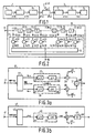
- the transmitter 1 comprises a data source 4 to which a modulator 5 is connected for modulating a signal x(n) produced by the data source on a carrier.
- the modulation signal u(n) thus obtained is smeared by means of a transversal smearing filter 6 and applied as a signal u'(n) to the transmission channel 2.
- impulse noise p(n) is added to the signal.
- a signal v'(n) applied to the receiver 3 via the transmission channel 2 is smeared by a transversal desmearing filter 7 and applied as a signal v(n) to a demodulator 8.
- the demodulated signal t'(n) is further processed in a data processing arrangement 9.
- FIG. 2 shows an embodiment of a transversal filter 10.
- a filter comprises a cascade arrangement of N-1 delay elements 11(0) to 11 (N-2), each having a time delay T equal to the sampling frequency of the signals x(n T ) applied to the input terminal 17.
- the sampling period T is less than the symbol period T, as will be explained in greater detail in an embodiment of a speech band signal.
- the cascade arrangement 11 (0) to 11 (N-2) can be realized in a simple way as a digital embodiment using a shift register or as an analogue embodiment using what is commonly denoted as a bucket memory.
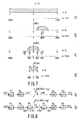
- a tap 12(0) is connected to the input of the first delay element 11 (0), the taps 12(1); 12(2)...; 12(N-3); 12(N-2) are connected to the junction between two consecutive elements 11(0)-11(1); 11(1) ⁇ 11(2); ...; 11 (N-3)-11 (N-2), respectively and the tap 12(N-1) is connected to the output of the last element 11 (N-2).
- the taps are connected to a signal processing arrangement 13 for multiplying by means of multiplier arrangements 14(0) to 14(N-1) the signals x(n T )' present on the taps 12(0) to 12(N-1) by coefficients c(0) to c(N-1) applied individually thereto.
- multipliers may be of an analogue construction, for example potentiometers, whose taps represent the values of the coefficients c(n).
- the product signals thus obtained are summed at least every symbol interval in a summing arrangement 15 and applied as an output signal 2 n c(n)x(n T ) to output 16.
- a transmission system in accordance with the invention for the transmission of data signals in a modulation band with a subtantially optimum smearing efficiency of noise pulses will be described in greater detail with reference to a transmission system operating in the speech band from 600 to 3000 Hz.
- the data source 4 supplies a 4800 bits/sec data signal and the modulator 5 modulates in 8-stages a carrier signal having a frequency f c of 1800 Hz.
- Figure 3a shows a block circuit diagram of an embodiment 5' of the modulator 5, based on signals having real values and Figure 3b shows a block circuit diagram of an equivalent representation of this embodiment 5" for signals having complex values.
- the encoding arrangement 22 shown in Figure 3a applies the real portion Re(x) of the complex numbers x(n) to a first interpolating filter 23 and the imaginary portion lm(x) of x(n) to a second interpolating filter 24, which filter 24 is identical to the first filter 23.
- interpolating filters each comprise an interpolator 25, 27 and transmit filters 26 and 28 connected thereto, both having an impulse response g(n).
- interpolators 25, 27 five samples having zero values are inserted in known manner between every two consecutive signal samples applied thereto, as a result of which the sampling rate is increased by a factor of 6 to 9600 Hz.
- the transmit filters 26 and 28 the baseband signal is filtered from the sequences supplied by the interpolators 25 and 27.
- the sequence x(n) produced by the encoding arrangement 42 is applied to a complex interpolating filter 43 in which the sampling frequency is similarly increased by a factor of 6 to 9600 Hz in an interpolator 44 and thereafter filtered in the transmit filter 45 having an impulse response g(n).
- the values of the impulse response g(n) are obtained by clipping the sequences obtained by an inverse Fourier transform of an ideal transmission function G( ⁇ ) given by
- This transmission function is also used in a corresponding filter in the receiver, but the filter then is a band-pass filter centred around the 1800 Hz carrier frequency.
- the transmission function is such that the cascade arrangement of the transmit filter and the receive filter is defined by the first Nyquist criterion, which requires that
- the signals supplied by the first and second interpolation filters 23 and 24 are thereafter modulated in known manner on a carrier having a frequency f . of 1800 Hz, with the aid of first and second multiplier arrangements 29 and 30 to which also the signals are applied wherein
- the speech band signal thus obtained only has a contribution in the interval corresponding to a frequency band from 600 Hz to 3000 Hz, designated speech band hereinafter.
- the spectrum X( ⁇ ) of the input signal is periodic, with a period of 2n
- the spectrum of the output signal u(n) can be written as follows.
- ⁇ c 2 ⁇ f c /f s and denotes the complex conjugate value.
- the spectrum of the output signal u'(n) of the transmitter 1 can be written as where C s ( ⁇ ) represents the transmission function of the smearing filter 6.
- this output signal u'(n) is converted into an analogue signal and transmitted to the receiver 3 via the transmission channel 2.
- the received signal is applied to the desmearing filter 7 via an anti-aliasing filter and A/D converter, not shown.
- the influence of these elements may be left out of consideration because of the fact that in said frequency range they have a flat transmission function.
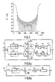
- Figure 6a shows an embodiment 8', with digital real signal values for the demodulator 8 of Figure 2 and in Figure 6b an equivalent representation is given of the embodiment 8" with complex signal values.
- These demodulators operate with a sampling frequency f s of 9600 Hz.
- the demodulator 8' comprises a quadrature receiver followed by a decoding arrangement 51.
- a flat input spectrum is assumed.
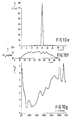
- the signal v(n) applied in Figure 6b to the input terminal 52 is converted in the complex digital filter 53 which is used as a receiving filter and has an impulse response g(n) e j ⁇ cn into the complex digital signal r(n) whose amplitude spectrum R( ⁇ ) is shown in Figure 7b.
- the impulse response of the receiving filter 53 is chosen such that the transmission function of this filter is a frequency-shifted version of the transmit filter of Figure 3b so that constraint (3) is satisfied.
- the digital signals Re r(n) and Im r(n) are demodulated as follows.
- the sampling frequency f s of the digital signals Re s(n) and lm s(n) are divided in known manner by a factor of six to 1600 Hz with the aid of the arrangements 49 and 50, shown in Figure 6a, which produces the digital signals Re t(n) and lm t(n).
- Figure 6b the sampling frequency of the digital complex signal s(n) is reduced to 1600 Hz by the arrangement 55.
- of the signal t(n) thus obtained is shown in Figure 7d. This Figure clearly shows folding of the amplitude spectrum
- the spectrum V(8) of the signal applied to the demodulator 8" is equal to the spectrum U( ⁇ ) of the output signal of modulator 5" and as the product of the transmit filter (26, 28; 45) and the receiving filter (33, 34; 53) satisfies the first Nyquist criterion, the contribution in T(8) of the folded portions is coherently added to the contribution of the remaining portion and for T(8) the spectrum x( ⁇ ) as shown in Figure 4a is accurately obtained. Because of clipping and rounding of the filter coefficients some symbol interference is however produced, which for the 29-tap FIR filter used is so small as to be disregarded.
- the signals Re t(n) and lm t(n) are converted in known manner into binary data signals of 4800 bits/sec with the aid of the decoding arrangement 51 of Figure 6a, the same operation being effected for signal t(n) with the aid of the decoding arrangement 56 of Figure 6b.
- the last term of (8) may be disregarded and it holds that: where If the smearing filter 6 and the desmearing filter 7 have the impulse responses c s (n) and c d (n) with the transmission functions C s ( ⁇ ) and C d ( ⁇ ), the frequency spectrum T'(0) of the complex digital signal t'(n) can be written, when the transmit filter 45 and the receiving filter 53 have a large attenuation in the stopband, as where Equivalent circuit diagrams of the transmission systems represented by the expressions (9) and (11) without and with smearing and desmearing filters are shown in Figures 8a and 8b.
- These systems both comprise, in succession, an arrangement 57 for increasing the sampling frequency by a factor of 6, a transmit filter 58 and a receiving filter 62 and an arrangement 63 for reducing the sampling frequency by a factor of 6, the system shown in Figure 8b also comprising a smearing filter 59 and a desmearing filter 61.
- merit factors F, and F 2 are derived which are a measure of the smearing efficiency of the impulsive noise and a measure of the ratio of the signal to the symbol interference generated by the combination of the smearing and desmearing filter itself respectively.
- the signal amplitudes of the signals in the system must be normalized to prevent the smearing filter 6 from having too high a gain factor, which implies an increase of the power on the transmission path 2, for example a telephone line.
- the desired component may be defined as h(0) and h'(0), where h(n) and h'(n) are the inverse Fourier transforms of the transfer functions H(6) and H'(6) defined in the expression (10) and (12).
- the smearing efficiency is defined on the basis of one single noise pulse for a shorter duration than the sampling period with amplitude K, which occurs at any instant no, so that it holds that for the impulsive noise p(n) shown in Figure 1. Let it be assumed that the interval between the noise pulses exceeds the duration of the impulse response of the filters.
- the accent notation further indicates impulsive noise of a shorter duration than the sampling period T .
- n o has been chosen at random (6n-no) may have any arbitrary value and in (25) the maximum across all values of n must be determined.
- impulsive noise formed by two consecutive pulses of equal amplitudes but of opposite polarity, denoted bipolar pulses in the following, designated by ". It then holds that: For such impulsive noise the output signal is if no smearing and desmearing filters are used, and is equal to when such filters are present in the system.
- the first merit factor may have many values, each adapted to a special model of the impulsive noise.
- the factor F' 1 which in accordance with the expression (25) apparently only depends on the coefficients of the desmearing filter, also depends on the smearing filter, more specifically because of the normalizations defined by (17) and (18).
- c d (n) is split as follows into two terms where K d is a real positive gain which is chosen such that where and q d (n) represents the characteristic of the desmearing filter.
- the signal sin n(n+1)n/2N is a frequency-modulated signal and has the instantaneous frequency So along the overall length of the impulse response b(n) this frequency is varied over the range
- the instantaneous frequency of the impulse response of the desmearing filter is varied only over the frequency range where ⁇ 1 and ⁇ 2 are the normalized cut-off frequencies of the band of the system, for example the cut-off frequency of the receive filter having the impulse response g(n).
- a speech band in the form of a modulation band there is a limitation of the frequency range from 1000 Hz f 2600 Hz, so a choice from This has the advantage that a high value can be realized for the first merit factor F 1 .
- the filter g(n) is not an ideal low-pass filter, and it has contributions over a larger frequency range, so that the above choice for ⁇ 1 and ⁇ 2 does not give an optimum value for the second merit factor F 2 .
- sequences c(n) with a substantially optimum smearing efficiency are derived therefrom in the following manner.
- a predetermined number much less than 1, for example 0.01 is added to or subtracted from the coefficients b(n) of a good ternary sequence and it is determined whether the sequence produces or does not produce better or poorer merit factors. In case the merit factors are better, then b(n) is changed into the real number c(n). This procedure is repeated for all values of n for 0 ⁇ n ⁇ N-1. Then the procedure is repeated until no further improvements are obtained anymore. As in a transmission system only a certain amount of intersymbol interference is permissible, the starting point was ternary sequences with a second merit factor F 2 ⁇ 20 dB.
- the amplitude characteristic of the desmearing filter is the same as that of the smearing filter.
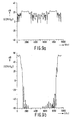
- Figure 9d shows the amplitude of the overall impulse response s(n) of the transmission system versus n and Figure 9e shows the amplitude of the decimated overall equivalent impulse response t'(n) of the system.
- the low value of intersymbol interference introduced by the smearing filter and the desmearing filter will be obvious from these Figures.
- the amplitude of a noise pulse p' as a function of n, which pulse is introduced into the transmission path and smeared in the receiver, is shown in Figure 9f.
- the substantially constant value of the smeared noise pulse with time is obtained in accordance with the invention by selecting those sequences c(n) for which F 1 is defined in (30b) and in this special case F' 1 of (25) has a substantially maximum value.
- the group delay time T g of the desmearing filter as shown in Table I is however no longer a linear function of the frequency as is shown in Figure 9g. This is however not objectionable, as long as the group delay time of the smearing filter is substantially complementary to that of the desmearing filter.
- the group delay time is not defined for two points as the transmission function of the smearing filter has a zero point for those values. These values are however located outside the 1000-2600 Hz frequency band used.
- Table II shows a sequence with real values for the coefficients c(n) for a filter having 64 coefficients with a substantially maximum value of the first merit factor F" 1 for bipolar noise pulses p"(n) such as they are defined in (30) and (27), respectively for a given value of the second merit factor F 2 .
- FIGS. 10a to 10g show for a transmission system comprising a smearing filter and a desmearing filter with coefficients as shown in Table III the graphs which correspond to the graphs shown in Figures 9a to 9g for a transmission system comprising filters in accordance with Table I.
- a comparison of Figure 10f with Figure 9f shows a still flatter smeared noise pulse for filters realized in accordance with Table I and consequently a still better smearing efficiency.
- sequences of real numbers c(n) which are realized in a different manner or are known per se from mathematics, can also be used as long as for a given noise pulse pattern p(n) and a given value of the second merit factor F 2 the value of the first merit factor F 1 associated with p(n) has a substantially maximum value, as given by (30b).
Claims (5)


Applications Claiming Priority (2)
| Application Number | Priority Date | Filing Date | Title |
|---|---|---|---|
| NL8400677 | 1984-03-02 | ||
| NL8400677A NL8400677A (nl) | 1984-03-02 | 1984-03-02 | Transmissiesysteem voor de overdracht van data signalen in een modulaatband. |
Publications (2)
| Publication Number | Publication Date |
|---|---|
| EP0155049A1 EP0155049A1 (fr) | 1985-09-18 |
| EP0155049B1 true EP0155049B1 (fr) | 1989-10-11 |
Family
ID=19843590
Family Applications (1)
| Application Number | Title | Priority Date | Filing Date |
|---|---|---|---|
| EP85200296A Expired EP0155049B1 (fr) | 1984-03-02 | 1985-02-28 | Système de transmission de signaux de données dans une bande de modulation |
Country Status (7)
| Country | Link |
|---|---|
| US (1) | US4660216A (fr) |
| EP (1) | EP0155049B1 (fr) |
| JP (1) | JPH0746810B2 (fr) |
| AU (1) | AU578870B2 (fr) |
| CA (1) | CA1230927A (fr) |
| DE (1) | DE3573697D1 (fr) |
| NL (1) | NL8400677A (fr) |
Families Citing this family (9)
| Publication number | Priority date | Publication date | Assignee | Title |
|---|---|---|---|---|
| NL8400676A (nl) * | 1984-03-02 | 1985-10-01 | Philips Nv | Data transmissie systeem. |
| US4731800A (en) * | 1986-10-03 | 1988-03-15 | Hycom Incorporated | Raised-cosine filtering for modems |
| US5818870A (en) * | 1990-08-28 | 1998-10-06 | Canon Kabushiki Kaisha | Digital communication device |
| US5825805A (en) * | 1991-10-29 | 1998-10-20 | Canon | Spread spectrum communication system |
| JP2002158561A (ja) * | 2000-11-20 | 2002-05-31 | Ando Electric Co Ltd | Firフィルタ及びそのデータ処理方法 |
| KR100446500B1 (ko) * | 2001-03-19 | 2004-09-04 | 삼성전자주식회사 | 비선형 왜곡 보상 방법 및 비선형 왜곡 보상 회로 |
| US6493668B1 (en) * | 2001-06-15 | 2002-12-10 | Yigal Brandman | Speech feature extraction system |
| US6937684B2 (en) * | 2001-10-02 | 2005-08-30 | Silicon Integrated Systems Corporation | Phase discriminator with a phase compensation circuit |
| CN107645461B (zh) * | 2016-07-22 | 2021-09-24 | 广东恒域科技股份有限公司 | 一种适用于OvXDM系统的调制方法、装置及OvXDM系统 |
Family Cites Families (8)
| Publication number | Priority date | Publication date | Assignee | Title |
|---|---|---|---|---|
| US3032725A (en) * | 1959-09-17 | 1962-05-01 | Bell Telephone Labor Inc | Pulse transmission |
| US3252093A (en) * | 1961-10-09 | 1966-05-17 | Massachusetts Inst Technology | Impulse noise suppression communication system utilizing matched filters and noise clipping |
| DE2020805C3 (de) * | 1970-04-28 | 1974-07-11 | Siemens Ag, 1000 Berlin Und 8000 Muenchen | Entzerrer zur Entzerrung von phasen- oder quadraturmodulierten Datensignalen |
| US4121295A (en) * | 1977-04-07 | 1978-10-17 | Wittronics, Inc. | Integer weighted impulse equivalent coded signal processing apparatus |
| JPS5558612A (en) * | 1978-10-26 | 1980-05-01 | Kokusai Denshin Denwa Co Ltd <Kdd> | Delay circuit |
| US4524424A (en) * | 1982-02-18 | 1985-06-18 | Rockwell International Corporation | Adaptive spectrum shaping filter |
| JPS5928740A (ja) * | 1982-08-10 | 1984-02-15 | Nippon Telegr & Teleph Corp <Ntt> | 通信方式 |
| NL8400676A (nl) * | 1984-03-02 | 1985-10-01 | Philips Nv | Data transmissie systeem. |
-
1984
- 1984-03-02 NL NL8400677A patent/NL8400677A/nl not_active Application Discontinuation
-
1985
- 1985-02-27 CA CA000475297A patent/CA1230927A/fr not_active Expired
- 1985-02-28 EP EP85200296A patent/EP0155049B1/fr not_active Expired
- 1985-02-28 DE DE8585200296T patent/DE3573697D1/de not_active Expired
- 1985-03-01 JP JP60038999A patent/JPH0746810B2/ja not_active Expired - Lifetime
- 1985-03-01 AU AU39404/85A patent/AU578870B2/en not_active Expired - Fee Related
- 1985-03-04 US US06/707,701 patent/US4660216A/en not_active Expired - Lifetime
Non-Patent Citations (1)
| Title |
|---|
| PATENTS ABSTRACTS OF JAPAN, vol. 7, no. 80, (E-168) [1225], April 2, 1983, & JP - A - 58 79 35 KOKUSAI DENSHIN DENWA K.K.) 17-01-1983 * |
Also Published As
| Publication number | Publication date |
|---|---|
| US4660216A (en) | 1987-04-21 |
| CA1230927A (fr) | 1987-12-29 |
| DE3573697D1 (en) | 1989-11-16 |
| AU578870B2 (en) | 1988-11-03 |
| JPH0746810B2 (ja) | 1995-05-17 |
| EP0155049A1 (fr) | 1985-09-18 |
| AU3940485A (en) | 1985-09-05 |
| NL8400677A (nl) | 1985-10-01 |
| JPS60206248A (ja) | 1985-10-17 |
Similar Documents
| Publication | Publication Date | Title |
|---|---|---|
| Hirosaki et al. | Advanced groupband data modem using orthogonally multiplexed QAM technique | |
| US5237292A (en) | Quadrature amplitude modulation system with compensation for transmission system characteristics | |
| US4358853A (en) | Digital modem transmitter | |
| US7800491B2 (en) | Power-line carrier communication apparatus | |
| US5459749A (en) | Multi-level superposed amplitude-modulated baseband signal processor | |
| CA1168331A (fr) | Eliminateur d'echo | |
| KR101015096B1 (ko) | 통신 장치 | |
| EP0194903B1 (fr) | Modulateur numérique à modulation d'amplitude en quadrature | |
| EP0155048B1 (fr) | Système de transmission de données | |
| GB2118406A (en) | A transmitter arranged for transmitting frequency-modulated signals | |
| EP0155049B1 (fr) | Système de transmission de signaux de données dans une bande de modulation | |
| CA1042514A (fr) | Systeme de transmission de donnees numeriques | |
| US4617537A (en) | Method for digital quadrature amplitude modulation | |
| US5768317A (en) | Equalization filter compensating for distortion in a surface acoustic wave device | |
| US6052037A (en) | Modulation method and apparatus | |
| US6535073B1 (en) | Device and method for I/Q modulation, frequency translation and upsampling | |
| US4438413A (en) | Serial minimum shift keyed modulator including notch and bandpass filters | |
| EP0244057B1 (fr) | Système de communication, récepteur et émetteur et méthode de récupération de données | |
| US5319676A (en) | Digital pre-modulation filter | |
| US5657353A (en) | Pulse shaping filter for received digital transmissions using phase lock loop for adjusting shift register | |
| EP0529144A1 (fr) | Annuleur d'écho lointain | |
| US6381623B1 (en) | Method for adaptive filter adjustment in a QAM/CAP system | |
| US6968016B1 (en) | Device and method for I/Q modulation, frequency translation and upsampling | |
| EP0453734A2 (fr) | Modem comportant des filtres à ondes acoustiques de surface ayant des caractéristiques opposées de retard en bande passante | |
| KR100433635B1 (ko) | 댁내 데이터 통신을 위한 변조기 |
Legal Events
| Date | Code | Title | Description |
|---|---|---|---|
| PUAI | Public reference made under article 153(3) epc to a published international application that has entered the european phase |
Free format text: ORIGINAL CODE: 0009012 |
|
| AK | Designated contracting states |
Designated state(s): BE CH DE FR GB IT LI NL SE |
|
| 17P | Request for examination filed |
Effective date: 19860317 |
|
| 17Q | First examination report despatched |
Effective date: 19871028 |
|
| GRAA | (expected) grant |
Free format text: ORIGINAL CODE: 0009210 |
|
| AK | Designated contracting states |
Kind code of ref document: B1 Designated state(s): BE CH DE FR GB IT LI NL SE |
|
| PG25 | Lapsed in a contracting state [announced via postgrant information from national office to epo] |
Ref country code: NL Effective date: 19891011 Ref country code: LI Effective date: 19891011 Ref country code: CH Effective date: 19891011 |
|
| REF | Corresponds to: |
Ref document number: 3573697 Country of ref document: DE Date of ref document: 19891116 |
|
| ITF | It: translation for a ep patent filed |
Owner name: ING. C. GREGORJ S.P.A. |
|
| ET | Fr: translation filed | ||
| REG | Reference to a national code |
Ref country code: CH Ref legal event code: PL |
|
| NLV1 | Nl: lapsed or annulled due to failure to fulfill the requirements of art. 29p and 29m of the patents act | ||
| PLBE | No opposition filed within time limit |
Free format text: ORIGINAL CODE: 0009261 |
|
| STAA | Information on the status of an ep patent application or granted ep patent |
Free format text: STATUS: NO OPPOSITION FILED WITHIN TIME LIMIT |
|
| 26N | No opposition filed | ||
| ITTA | It: last paid annual fee | ||
| EAL | Se: european patent in force in sweden |
Ref document number: 85200296.3 |
|
| PGFP | Annual fee paid to national office [announced via postgrant information from national office to epo] |
Ref country code: BE Payment date: 19950201 Year of fee payment: 11 |
|
| ITPR | It: changes in ownership of a european patent |
Owner name: CAMBIO RAGIONE SOCIALE;PHILIPS ELECTRONICS N.V. |
|
| REG | Reference to a national code |
Ref country code: FR Ref legal event code: CD |
|
| PGFP | Annual fee paid to national office [announced via postgrant information from national office to epo] |
Ref country code: SE Payment date: 19960223 Year of fee payment: 12 |
|
| PG25 | Lapsed in a contracting state [announced via postgrant information from national office to epo] |
Ref country code: BE Effective date: 19960228 |
|
| BERE | Be: lapsed |
Owner name: PHILIPS ELECTRONICS N.V. Effective date: 19960228 |
|
| PG25 | Lapsed in a contracting state [announced via postgrant information from national office to epo] |
Ref country code: SE Effective date: 19970301 |
|
| EUG | Se: european patent has lapsed |
Ref document number: 85200296.3 |
|
| REG | Reference to a national code |
Ref country code: FR Ref legal event code: CD |
|
| PGFP | Annual fee paid to national office [announced via postgrant information from national office to epo] |
Ref country code: GB Payment date: 20000228 Year of fee payment: 16 |
|
| PGFP | Annual fee paid to national office [announced via postgrant information from national office to epo] |
Ref country code: DE Payment date: 20000419 Year of fee payment: 16 |
|
| PGFP | Annual fee paid to national office [announced via postgrant information from national office to epo] |
Ref country code: FR Payment date: 20010216 Year of fee payment: 17 |
|
| PG25 | Lapsed in a contracting state [announced via postgrant information from national office to epo] |
Ref country code: GB Free format text: LAPSE BECAUSE OF NON-PAYMENT OF DUE FEES Effective date: 20010228 |
|
| GBPC | Gb: european patent ceased through non-payment of renewal fee |
Effective date: 20010228 |
|
| PG25 | Lapsed in a contracting state [announced via postgrant information from national office to epo] |
Ref country code: DE Free format text: LAPSE BECAUSE OF NON-PAYMENT OF DUE FEES Effective date: 20011201 |
|
| PG25 | Lapsed in a contracting state [announced via postgrant information from national office to epo] |
Ref country code: FR Free format text: LAPSE BECAUSE OF NON-PAYMENT OF DUE FEES Effective date: 20021031 |
|
| REG | Reference to a national code |
Ref country code: FR Ref legal event code: ST |