EP0154795A2 - Vorrichtung zum selektiven galvanischen Beschichten eines Bandes - Google Patents
Vorrichtung zum selektiven galvanischen Beschichten eines Bandes Download PDFInfo
- Publication number
- EP0154795A2 EP0154795A2 EP85101019A EP85101019A EP0154795A2 EP 0154795 A2 EP0154795 A2 EP 0154795A2 EP 85101019 A EP85101019 A EP 85101019A EP 85101019 A EP85101019 A EP 85101019A EP 0154795 A2 EP0154795 A2 EP 0154795A2
- Authority
- EP
- European Patent Office
- Prior art keywords
- tape
- roller
- reservoir
- elongate
- anyone
- Prior art date
- Legal status (The legal status is an assumption and is not a legal conclusion. Google has not performed a legal analysis and makes no representation as to the accuracy of the status listed.)
- Granted
Links
Images


Classifications
-
- C—CHEMISTRY; METALLURGY
- C25—ELECTROLYTIC OR ELECTROPHORETIC PROCESSES; APPARATUS THEREFOR
- C25D—PROCESSES FOR THE ELECTROLYTIC OR ELECTROPHORETIC PRODUCTION OF COATINGS; ELECTROFORMING; APPARATUS THEREFOR
- C25D5/00—Electroplating characterised by the process; Pretreatment or after-treatment of workpieces
- C25D5/02—Electroplating of selected surface areas
-
- C—CHEMISTRY; METALLURGY
- C25—ELECTROLYTIC OR ELECTROPHORETIC PROCESSES; APPARATUS THEREFOR
- C25D—PROCESSES FOR THE ELECTROLYTIC OR ELECTROPHORETIC PRODUCTION OF COATINGS; ELECTROFORMING; APPARATUS THEREFOR
- C25D7/00—Electroplating characterised by the article coated
- C25D7/06—Wires; Strips; Foils
- C25D7/0614—Strips or foils
- C25D7/0621—In horizontal cells
-
- C—CHEMISTRY; METALLURGY
- C25—ELECTROLYTIC OR ELECTROPHORETIC PROCESSES; APPARATUS THEREFOR
- C25D—PROCESSES FOR THE ELECTROLYTIC OR ELECTROPHORETIC PRODUCTION OF COATINGS; ELECTROFORMING; APPARATUS THEREFOR
- C25D7/00—Electroplating characterised by the article coated
- C25D7/06—Wires; Strips; Foils
- C25D7/0614—Strips or foils
- C25D7/0671—Selective plating
Definitions
- the invention relates to an electroplating device for locally applying a metal deposit to an elongate metal tape or to metal objects united in an elongate tape or the like in which the tape is guided along a roller adapted to rotate about a rotary axis during operation and being dipped at least partly in an electrolyte solution, whilst the tape is displaced parallel to the rotary axis of the roller in a manner such that the areas of the tape to be provided with the metal deposit come into contact with the roller.
- Such a device is known from U.S. Patent Specification 4,119,499 and is often used for locally applying a film of metal, frequently precious metal to, for example, parts used in the electronic industry as switching or connecting elements.
- a satisfactory deposit of precious metal is required, whereas on the other hand for reasons of costs the consumption of the precious metals for the application of the metal layer has to be minimized.
- a further disadvantage of this known device is the complicated structure required for correctly guiding the belts through the device together with the elongate tape to be processed between the belts.
- the device embodying the invention comrpises a guide surface which is stationary during operation and along which the tape is transported during operation and a guiding rim extending parallel to the rotary axis of the roller and protruding out of the guiding surface for the edge of the elongate tape remote from the roller, against which rim the edge of the elongate tape is pressed with the aid of wheels pressing the tape against the guiding surface and having their rotary axes at an acute angle to the direction of transport of the tape.
- U.S. Patent Specification 4,010,083 describes a device, in which a cylinder partly dipped in an electrolyte solution, is provided at one end with a narrow, protruding rim. Along this rim a metal tape to be plated with precious metal is guided parallel to the rotary axis of the cylinder.
- a first disadvantage of this device is that there is a very short period of contact between the cylinder and the area of the tape to be plated, unless the tape is transported with an unacceptable low speed with regard to the required production capacity.
- a second disadvantage is that the tape is not guided so that due to its contact with the cylinder the tape will vibrate transversely of its direction of length, which will strongly reduce the desired accuracy of the application of the metal deposit.
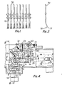
- the electroplating device embodying the invention comprises an elongate, channel-section reservoir 1. To the ends of the reservoir are fastened U-shaped brackets 2 located between adjustment nuts 3 and 4 fastened onto stub shafts 5. The lower ends of the stubs 5 are screwed into nuts 6 welded to a supporting frame 7', which may also serve to support further devices (not shown) with the aid of which the tape to be plated in the device embodying the invention, may be subjected to further treatments.
- the reservoir 1 is adjustable in a direction of height.
- a plate 7 extending parallel to the bottom of the reservoir and having passages 8. Above the plate 7 the reservoir has an anode 9.
- a length of pipe 10 is welded, extending downwards from said bottom and having its lower end arranged in a feed pipe 11 attached to the frame.
- the lower end of the length of pipe 10 is sealed with respect to the inner wall of the length of pipe 11 with the aid of a sealing ring 12.
- a semi-circular covering hood 13 which laterally conducts the elecrolyte, fed to the reservoir 1, so that this electrolyte spreads throughout the length of the reservoir 1 below the plate 7 before it flows through the openings 8 to the upper part of the reservoir. Electrolyte flowing across the top rims of the reservoir can be conducted away through an outlet pipe 14 connected with the frame 7'.
- a roller 15 is arranged, rotatable about a horizontal rotary shaft 16.
- the roller 15 comprises a central shaft 17 to which two aligned, cylindrical bodies 18 and 19 are fastened.
- the outer circumference of the roller is formed by an over-layer 20 applied to said cylindrical bodies 18 and 19 and made from moisture-absorbing material.
- the disposition of the roller is such that, as will be apparent in particular from Fig. 4, the lower part of the roller is dipped in the electrolyte contained in the reservoir 1.
- the electrolyte can be carried upwards by the moisture-absorbing layer 20.
- the ends of the shaft 17 are provided with stubs 21 and 22 which are rotatably positioned in bearings 23 and 24 supported by plates 25 and 26 respectively attached to the frame 7'.
- One end of the stub shaft 22 has attached to it a toothed belt pulley 27, which is coupled through a toothed belt 28 with a toothed belt pulley 29 which can be rotated by a driving motor 30.
- a pressure roller 31 is arranged parallel to and, as viewed in Fig. 5, behind the roller 15 in a manner such that the rotary shaft of the roller 31 is located in the same horizontal plane as the rotary shaft 16 of the roller 15.
- the ends of the roller 31 are provided with stub shafts 32 with the aid of which the roller 31 is freely rotatable about its rotary axis and positioned in supporting strips 33, which are supported by plates 25 and 26 in a manner such that these supporting strips are adjustable in a horizontal direction and at right angles to the rotary shaft of the roller 31.
- the supporting strips are coupled with one another by means of a rod 34 extending parallel to the roller 31.
- the rod 34 is adjustably connected with the aid of a coupling rod 35 with the lower end of an arm 36, the top end of which is fixed to a shaft 37 extending parallel to the rod 34 and being rotatably positioned in the plates 25 and 26.
- a coupling rod 35 with the lower end of an arm 36, the top end of which is fixed to a shaft 37 extending parallel to the rod 34 and being rotatably positioned in the plates 25 and 26.
- an upwardly extending arm 38 is coupled which is provided with a locking knob 39 which can be used for fixing the shaft 37 in a given position, to engage one of a plurality of locking openings 40 in the plate 25 located on an are of a circle concentric with the centre line of the shaft 37.
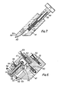
- an elongate supporting block 41 extends parallel to the roller, to which block a guide member 42 is fastened for guiding the elongate tape to be plated.
- the supporting block 41 is connected with the aid of two adjustment bolts 43 extending normal to the direction of length of the supporting block with a supporting rod 44 so that with the aid of the bolts 43 the supporting block is adjustable with respect to the supporting rod 44.
- the ends of the supporting rod 44 are rotatably positioned in the supporting plates 25 and 26 so that the supporting block is pivotable about a pivotal axis parallel to the axis of rotation of the roller 15.
- Fig. 4 furthermore shows that recesses 45 are provided in the supporting block at right angles to the direction of length of the adjustment bolts 43 for receiving pins 46, whose ends, protruding out of the supporting block, are in contact with stops 47 fastened to the plates 25 and 26.
- the recesses 45 furthermore hold compression springs 48 loading the pins 46 and being enclosed between the ends of the pins and covering plates 49 fastened to the supporting block and covering the recesses 45.
- the ends of adjustment bolts 50 rest, which are screwed into tapped holes in brackets 51 attached to the supporting plates 25 and 26.
- the guide member 42 has a stepped top surface, a face 52 which, extending parallel to the rotary axis, constitutes a guide face for the elongate tape to be transported through the device and a rim 53 at right angles to said face, which constitutes an upper guide rim for the elongate tape.
- each housing 57 is pivotally connected to a supporting piece 59 with the aid of a horizontal pivot pin 58 extending at right angles to the shaft 56.
- the supporting piece 59 is connected with the supporting block 41 with the aid of a spring-loaded bolt 60 crossing the shafts 56 and 58 at right angles and can be fixed in various positions with respect to said supporting block by means of a clamping bolt 61.
- the shaft 56 of the hweel 55 is revolving in a sleeve 64 arranged in the housing 57 and being adjustable in the direction of length of the shaft 56 with respect to the housing 57 and fixable in the desired position by means of a guard bolt 65.
- the plates 25 and 26 supporting the supporting block 41 and the parts fastened thereto and the two rollers 15 and 31 are clamped tight to supporting strips 67 fastened to the frame 7' with the aid of bolts 68 and 69 passed through vertical slots in the strips 69.
- the bolts 68 are passed through sleeves 70 fastened to the lower ends of vertical stubs 71.
- the stubs are passed through holes in supporting plates 72 fastened to the frame 7', whilst nuts 73 are screwed onto the ends of the stubs located above the supporting plates 72.
- the device is particularly intended for the local application of a metal coating to tape-shaped material to be passed through the device.
- a potential embodiment of such an elongate tape is shown in Fig. 1.
- the elongate tape comprises a plurality of elongate metal contact parts 74 punched from strip-shaped material and adhering to one another by bridges 75 integral with said contact parts.
- one end 76 of the contact part 74 is curved; it may be desired, for example, to provide the convex side 77 of this curved part 76 with a metal coating, for example, of gold or similar material.
- the tape is passed through the device described above so that the ends of the elongate objects 75 remote from the curved parts 76 are guided along the guide face 52 and thus urged against this guide face by the wheels 55.
- the housings 57 supporting the wheels 55 will arrive by turning about the bolts 60 at a position in which the rotary axes of the wheels 55 are upwardly inclined to the left (Fig. 3). Therefore, the freely rotating wheels 55, which urge the endless tape, as stated above, against the guide face 52 of the guide member 42, will also tend to displace the tape upwards, as viewed in Fig. 3, so that the ends of the elongate objects are pressed against the guide rim 53. It will be obvious that in this way an accurate positioning of the elongate tape with respect to the guide member 42 is obtained.
- the correct position of the guide member 42 with respect to the roller 50 can be ensured prior to starting the treatment of the metal tape by correct adjustment of the supporting block with the aid of the adjustment bolts 43 so that the guide rim 53 extends parallel to the rotary shaft of the roller 15 and with the aid of the adjustment bolts 50 so that the guide face 52 is also parallel to the rotary axis of the roller 15 and the curved parts 76 come just into contact by their curved faces 77 with the fluid-absorbing layer 20 of the roller 15 during operation.
- the anode is arranged at a relatively large distance from the curved surface 77 so that substances which may be set free at the anode and which might have an adverse effect on the metal deposition to be obtained will not come into contact with the metal tape.
- a tape may, as an alternative, be passed from right to left through the device, as viewed in Fig. 3, in which case the wheels 55 are disposed so that, as shown in Fig. 3, the rotary axes are upwardly inclined to the right.
Landscapes
- Chemical & Material Sciences (AREA)
- Engineering & Computer Science (AREA)
- Chemical Kinetics & Catalysis (AREA)
- Electrochemistry (AREA)
- Materials Engineering (AREA)
- Metallurgy (AREA)
- Organic Chemistry (AREA)
- Electroplating Methods And Accessories (AREA)
Priority Applications (1)
| Application Number | Priority Date | Filing Date | Title |
|---|---|---|---|
| AT85101019T ATE41956T1 (de) | 1984-02-09 | 1985-01-31 | Vorrichtung zum selektiven galvanischen beschichten eines bandes. |
Applications Claiming Priority (2)
| Application Number | Priority Date | Filing Date | Title |
|---|---|---|---|
| US578581 | 1984-02-09 | ||
| US06/578,581 US4618407A (en) | 1984-02-09 | 1984-02-09 | Galvano-technical device for locally applying a metal layer to an elongate metal tape or the like |
Publications (3)
| Publication Number | Publication Date |
|---|---|
| EP0154795A2 true EP0154795A2 (de) | 1985-09-18 |
| EP0154795A3 EP0154795A3 (en) | 1986-12-17 |
| EP0154795B1 EP0154795B1 (de) | 1989-04-05 |
Family
ID=24313469
Family Applications (1)
| Application Number | Title | Priority Date | Filing Date |
|---|---|---|---|
| EP85101019A Expired EP0154795B1 (de) | 1984-02-09 | 1985-01-31 | Vorrichtung zum selektiven galvanischen Beschichten eines Bandes |
Country Status (5)
| Country | Link |
|---|---|
| US (1) | US4618407A (de) |
| EP (1) | EP0154795B1 (de) |
| JP (1) | JPS60187697A (de) |
| AT (1) | ATE41956T1 (de) |
| DE (1) | DE3569268D1 (de) |
Cited By (1)
| Publication number | Priority date | Publication date | Assignee | Title |
|---|---|---|---|---|
| DE3839223C1 (de) * | 1988-11-19 | 1989-12-07 | Degussa Ag, 6000 Frankfurt, De |
Family Cites Families (6)
| Publication number | Priority date | Publication date | Assignee | Title |
|---|---|---|---|---|
| US3539490A (en) * | 1967-11-28 | 1970-11-10 | Sylvania Electric Prod | Plating of stripes on longitudinal electrically conductive material |
| US3661752A (en) * | 1970-06-23 | 1972-05-09 | Amp Inc | Belt plating apparatus |
| NL7401595A (nl) * | 1974-01-21 | 1975-07-23 | Galentan Ag | Inrichting voor het kontinu aanbrengen van strook-, lint- of vlekvormige bedekkingen. |
| US3966581A (en) * | 1974-10-16 | 1976-06-29 | Auric Corporation | Selective plating apparatus |
| US4078982A (en) * | 1976-03-15 | 1978-03-14 | Dixie Plating, Inc. | Apparatus for continuous contact plating |
| US4220504A (en) * | 1979-04-16 | 1980-09-02 | Burton Silverplating Company | Selective electroplating |
-
1984
- 1984-02-09 US US06/578,581 patent/US4618407A/en not_active Expired - Fee Related
-
1985
- 1985-01-31 DE DE8585101019T patent/DE3569268D1/de not_active Expired
- 1985-01-31 EP EP85101019A patent/EP0154795B1/de not_active Expired
- 1985-01-31 AT AT85101019T patent/ATE41956T1/de not_active IP Right Cessation
- 1985-02-08 JP JP60022097A patent/JPS60187697A/ja active Pending
Cited By (1)
| Publication number | Priority date | Publication date | Assignee | Title |
|---|---|---|---|---|
| DE3839223C1 (de) * | 1988-11-19 | 1989-12-07 | Degussa Ag, 6000 Frankfurt, De |
Also Published As
| Publication number | Publication date |
|---|---|
| JPS60187697A (ja) | 1985-09-25 |
| DE3569268D1 (en) | 1989-05-11 |
| EP0154795B1 (de) | 1989-04-05 |
| EP0154795A3 (en) | 1986-12-17 |
| ATE41956T1 (de) | 1989-04-15 |
| US4618407A (en) | 1986-10-21 |
Similar Documents
| Publication | Publication Date | Title |
|---|---|---|
| US4119499A (en) | Continuous contact plater product | |
| JPS6376898A (ja) | 板状物体の電解処理装置 | |
| US8277629B2 (en) | Continuous plating system and method with mask registration | |
| DE2166851A1 (de) | Einrichtung zum reinigen des aufzeichnungsmaterials eines elektrophotographischen kopiergeraets | |
| US4483106A (en) | Weld sander | |
| US4264416A (en) | Method for continuous application of strip ribbon or patch-shaped coatings to a metal tape | |
| US4132617A (en) | Apparatus for continuous application of strip-, ribbon- or patch-shaped coatings to a metal tape | |
| EP0154795A2 (de) | Vorrichtung zum selektiven galvanischen Beschichten eines Bandes | |
| DE4134418C2 (de) | Vorrichtung zum Transportieren von plattenförmigen Gegenständen | |
| US3185130A (en) | Multiple roller coating apparatus | |
| US4064019A (en) | Continuous contact plater method | |
| US5656086A (en) | Coating device for applying thin wet films | |
| US8287714B2 (en) | Continuous plating system and method with mask registration | |
| EP0708050B1 (de) | Kabeltransport- und Schwenkvorrichtung | |
| US4220504A (en) | Selective electroplating | |
| EP0361029B1 (de) | Galvanisiereinrichtung für plattenförmige Werkstücke, insbesondere Leiterplatten | |
| US4431124A (en) | Apparatus and method for guiding metal strip | |
| US20180327190A1 (en) | Return Idler Trainer | |
| FI76272B (fi) | Foerfarande och anordning foer slipning aeven av smao arbetsstycken. | |
| US4361470A (en) | Connector contact point | |
| US4036725A (en) | Wheel selective jet plating system | |
| GB2104025A (en) | Improvements in or relating to electro-plating machines | |
| CA1144522A (en) | Continuous contact plater | |
| JPS6338032Y2 (de) | ||
| DE3034381A1 (de) | Vorrichtung zum transportieren und foerdern von profilierten werkstuecken |
Legal Events
| Date | Code | Title | Description |
|---|---|---|---|
| PUAI | Public reference made under article 153(3) epc to a published international application that has entered the european phase |
Free format text: ORIGINAL CODE: 0009012 |
|
| AK | Designated contracting states |
Designated state(s): AT BE CH DE FR GB IT LI LU NL SE |
|
| PUAL | Search report despatched |
Free format text: ORIGINAL CODE: 0009013 |
|
| AK | Designated contracting states |
Kind code of ref document: A3 Designated state(s): AT BE CH DE FR GB IT LI LU NL SE |
|
| 17P | Request for examination filed |
Effective date: 19870122 |
|
| 17Q | First examination report despatched |
Effective date: 19871217 |
|
| GRAA | (expected) grant |
Free format text: ORIGINAL CODE: 0009210 |
|
| AK | Designated contracting states |
Kind code of ref document: B1 Designated state(s): AT BE CH DE FR GB IT LI LU NL SE |
|
| PG25 | Lapsed in a contracting state [announced via postgrant information from national office to epo] |
Ref country code: SE Effective date: 19890405 Ref country code: NL Effective date: 19890405 Ref country code: LI Effective date: 19890405 Ref country code: IT Free format text: LAPSE BECAUSE OF FAILURE TO SUBMIT A TRANSLATION OF THE DESCRIPTION OR TO PAY THE FEE WITHIN THE PRESCRIBED TIME-LIMIT;WARNING: LAPSES OF ITALIAN PATENTS WITH EFFECTIVE DATE BEFORE 2007 MAY HAVE OCCURRED AT ANY TIME BEFORE 2007. THE CORRECT EFFECTIVE DATE MAY BE DIFFERENT FROM THE ONE RECORDED. Effective date: 19890405 Ref country code: FR Free format text: THE PATENT HAS BEEN ANNULLED BY A DECISION OF A NATIONAL AUTHORITY Effective date: 19890405 Ref country code: CH Effective date: 19890405 Ref country code: BE Effective date: 19890405 Ref country code: AT Effective date: 19890405 |
|
| REF | Corresponds to: |
Ref document number: 41956 Country of ref document: AT Date of ref document: 19890415 Kind code of ref document: T |
|
| REF | Corresponds to: |
Ref document number: 3569268 Country of ref document: DE Date of ref document: 19890511 |
|
| REG | Reference to a national code |
Ref country code: CH Ref legal event code: PL |
|
| EN | Fr: translation not filed | ||
| NLV1 | Nl: lapsed or annulled due to failure to fulfill the requirements of art. 29p and 29m of the patents act | ||
| PG25 | Lapsed in a contracting state [announced via postgrant information from national office to epo] |
Ref country code: LU Free format text: LAPSE BECAUSE OF NON-PAYMENT OF DUE FEES Effective date: 19900131 |
|
| PGFP | Annual fee paid to national office [announced via postgrant information from national office to epo] |
Ref country code: GB Payment date: 19900131 Year of fee payment: 6 |
|
| PLBE | No opposition filed within time limit |
Free format text: ORIGINAL CODE: 0009261 |
|
| STAA | Information on the status of an ep patent application or granted ep patent |
Free format text: STATUS: NO OPPOSITION FILED WITHIN TIME LIMIT |
|
| PGFP | Annual fee paid to national office [announced via postgrant information from national office to epo] |
Ref country code: DE Payment date: 19900312 Year of fee payment: 6 |
|
| 26N | No opposition filed | ||
| PG25 | Lapsed in a contracting state [announced via postgrant information from national office to epo] |
Ref country code: GB Effective date: 19910131 |
|
| GBPC | Gb: european patent ceased through non-payment of renewal fee | ||
| PG25 | Lapsed in a contracting state [announced via postgrant information from national office to epo] |
Ref country code: DE Effective date: 19911001 |