EP0154261A2 - Method and apparatus for testing soil - Google Patents
Method and apparatus for testing soil Download PDFInfo
- Publication number
- EP0154261A2 EP0154261A2 EP85101908A EP85101908A EP0154261A2 EP 0154261 A2 EP0154261 A2 EP 0154261A2 EP 85101908 A EP85101908 A EP 85101908A EP 85101908 A EP85101908 A EP 85101908A EP 0154261 A2 EP0154261 A2 EP 0154261A2
- Authority
- EP
- European Patent Office
- Prior art keywords
- soil
- cylinder
- inner cylinder
- probe
- testing
- Prior art date
- Legal status (The legal status is an assumption and is not a legal conclusion. Google has not performed a legal analysis and makes no representation as to the accuracy of the status listed.)
- Granted
Links
- 239000002689 soil Substances 0.000 title claims abstract description 97
- 238000012360 testing method Methods 0.000 title claims abstract description 62
- 238000000034 method Methods 0.000 title claims abstract description 25
- 239000000523 sample Substances 0.000 claims abstract description 58
- 230000033001 locomotion Effects 0.000 claims abstract description 24
- 230000004044 response Effects 0.000 claims abstract description 24
- 230000005284 excitation Effects 0.000 claims abstract description 12
- 238000010998 test method Methods 0.000 claims description 2
- 230000015556 catabolic process Effects 0.000 abstract description 11
- 238000006731 degradation reaction Methods 0.000 abstract description 11
- 230000006835 compression Effects 0.000 abstract description 10
- 238000007906 compression Methods 0.000 abstract description 10
- 238000005259 measurement Methods 0.000 abstract description 7
- 230000000694 effects Effects 0.000 abstract description 3
- 230000003534 oscillatory effect Effects 0.000 abstract 1
- 238000011068 loading method Methods 0.000 description 21
- 230000035515 penetration Effects 0.000 description 15
- XLYOFNOQVPJJNP-UHFFFAOYSA-N water Substances O XLYOFNOQVPJJNP-UHFFFAOYSA-N 0.000 description 14
- 239000012530 fluid Substances 0.000 description 10
- 239000011148 porous material Substances 0.000 description 8
- 238000004458 analytical method Methods 0.000 description 7
- 238000006073 displacement reaction Methods 0.000 description 7
- 238000004891 communication Methods 0.000 description 6
- 125000004122 cyclic group Chemical group 0.000 description 6
- 238000011065 in-situ storage Methods 0.000 description 6
- 238000006243 chemical reaction Methods 0.000 description 4
- 230000007613 environmental effect Effects 0.000 description 3
- 238000009533 lab test Methods 0.000 description 3
- 230000035945 sensitivity Effects 0.000 description 3
- 238000010008 shearing Methods 0.000 description 3
- 239000004575 stone Substances 0.000 description 3
- 238000003780 insertion Methods 0.000 description 2
- 230000037431 insertion Effects 0.000 description 2
- 238000012986 modification Methods 0.000 description 2
- 230000004048 modification Effects 0.000 description 2
- 101100393871 Arabidopsis thaliana GT12 gene Proteins 0.000 description 1
- 239000004809 Teflon Substances 0.000 description 1
- 229920006362 Teflon® Polymers 0.000 description 1
- 230000009471 action Effects 0.000 description 1
- 238000013459 approach Methods 0.000 description 1
- 238000004364 calculation method Methods 0.000 description 1
- 230000001276 controlling effect Effects 0.000 description 1
- 238000007796 conventional method Methods 0.000 description 1
- 230000002596 correlated effect Effects 0.000 description 1
- 238000013461 design Methods 0.000 description 1
- 238000005553 drilling Methods 0.000 description 1
- 230000005489 elastic deformation Effects 0.000 description 1
- 238000005516 engineering process Methods 0.000 description 1
- 230000003993 interaction Effects 0.000 description 1
- 239000000463 material Substances 0.000 description 1
- 230000010355 oscillation Effects 0.000 description 1
- 238000004321 preservation Methods 0.000 description 1
- 230000008569 process Effects 0.000 description 1
- 238000011002 quantification Methods 0.000 description 1
- 230000009467 reduction Effects 0.000 description 1
- 229920006395 saturated elastomer Polymers 0.000 description 1
- 239000007787 solid Substances 0.000 description 1
- 230000003068 static effect Effects 0.000 description 1
- 238000012956 testing procedure Methods 0.000 description 1
Images


Classifications
-
- E—FIXED CONSTRUCTIONS
- E02—HYDRAULIC ENGINEERING; FOUNDATIONS; SOIL SHIFTING
- E02D—FOUNDATIONS; EXCAVATIONS; EMBANKMENTS; UNDERGROUND OR UNDERWATER STRUCTURES
- E02D1/00—Investigation of foundation soil in situ
- E02D1/02—Investigation of foundation soil in situ before construction work
- E02D1/022—Investigation of foundation soil in situ before construction work by investigating mechanical properties of the soil
Definitions
- This invention relates generally to techniques for testing soils, and particularly to techniques for testing soils involving the application of disturbances to an object embedded in the soil to evaluate the response of the object and the soil to such loading.
- Liquefaction is the total loss of the stiffness and strength of a saturated soil, caused by increased pore water pressure which can result from cyclic loading.
- Degradation is the reduction in stiffness also due to the buildup of pore water pressure caused by cyclic loading. Degradation may or may not lead to liquefaction depending on the type and state of the soil.
- the shear modulus is basically the shearing stiffness of a soil. Generally, the shear modulus of a soil is a function of shearing deformation. For example, most soils show reduced stiffness with increasing deformation under monotonically increasing loading.
- Laboratory testing of soil samples suffers from a number of problems. Particularly, the acts of recovering a sample, transporting it to a laboratory and preparing the sample for a test, can so disturb a sample from its original state, as to bring to question any results obtained. In addition, it is often difficult to reproduce the original field environment (state of stress) of the sample because it is often difficult and costly to define the environment and because typical laboratory test appa--ratus-are limited in their ability to reproduce environmental conditions. Because of the failure to precisely account for environmental considerations, laboratory tests are subject to error for this additional reason. Safely accounting for these disturbances and for environmental conditions may lead to excessively costly structures.
- Liquefaction resistance is generally tested in the field by a penetration test.
- a closed ended probe is either penetrated into the ground at a controlled slow rate, simulating static, non-cyclic loading but introducing severe failure into the local soil, or a cylinder is driven into the ground by violent impacts, also causing severe and immediate failure in the soil local to the cylinder.
- the resistance of the soil to liquefaction is correlated to the resistance of the probe or cylinder to penetration. Neither of these tests induces the type of loading generally induced by earthquakes or ocean waves which are the main known causes of liquefaction.
- in situ testing procedures have not been widely used to obtain degradation characteristics, a number of in situ tests have been used to determine the dynamic shear modulus and to a lesser extent, its variation with shear deformation. These include wave propagation tests, resonant footing tests and downhole probe tests. There are several different wave propagation techniques. With these techniques, the shear modulus of the soil is estimated from the measurement of some wave parameter, such as wave speed or wavelength. Each of these techniques has limitations or drawbacks.
- One technique known as “seismic crosshole testing" requires two or more bore holes with sensors, and a below ground excitation source, making it relatively expensive for testing in a normal environment and difficult to practice in an offshore environment.
- a second technique known as “seismic downhole testing” requires only one bore hole but is limited to measurements involving very low strain amplitude.
- a third technique known as “seismic refraction”, can result in poor definition of layering for sites where interbedded layers exist.
- a fourth technique involving surface wave generation, requires sizeable equipment to provide definition of layering to the depths typically of interest.
- the inventor of the present invention has identified certain characteristics that would be particularly advantageous if implemented in a single device. These characteristics include minimal soil disturbance by the testing probe, preservation of the original environment of the test soil, in situ testing using loading comparable to that experienced during the real life phenomena that induce soil failure, and the capability of providing liquefaction resistance, degradation characteristics, shear modulus, and the nonlinear variation in shear modulus with shear deformation. Further, it would be advantageous if such a device could readily enable the quantification of natural phenomena such as liquefaction and degradation.
- a method of testing soil includes the step of inserting a pair of concentric open ended cylinders into the soil to be tested.
- the inner of the cylinders is excited torsionally, resulting in its rotation through a limited arc of motion about its cylindrical axis. Measures of the resistance of the soil to the excitation of the inner cylinder are then obtained.
- a soil testing probe includes a pair of concentric open ended cylinders. Means are provided for inserting the cylinders open ends first, into a soil sample to be tested. Means apply a torque to the inner of the cylinders which, in response, rotates through a limited arc of motion, within the sample, about the cylindrical axis. Thereafter, means are provided for obtaining measures of the resistance of the soil to the excitation of the inner cylinder.
- the soil testing probe may include an open ended, cylindrical device and means for inserting the device open end first into the soil sample to be tested.
- a torque is applied to the device which, in response, rotates through a limited arc of motion within the sample about its cylindrical axis.
- measuring means are provided for obtaining a measure of the torque applied by the soil in opposition to the rotational motion of the device, by measuring the response of the device to the torque applied by the applying means.
- a soil testing probe for making tests beneath the soil surface includes a rotatable open ended cylinder insertable into a soil sample to be tested.
- a concentric shield is positionable in close relationship to the upper portion of the open ended cylinder. Means are provided for rotating the cylinder with respect to the shield.
- an apparatus for testing soil includes an open-ended probe insertable open end first into a soil sample to be tested. Means are provided for applying an oscillating force to the probe. Measuring means, give a measure of the resistance of the soil to the motion of the probe in response to the force.
- a soil testing apparatus 10 includes a control, recording, analysis and computation stand 12, a reaction frame 14, a rigid pipe 16, and a probe 18.
- a control, recording, analysis and computation stand 12 includes a reaction frame 14, a rigid pipe 16, and a probe 18.
- a rigid pipe apparatus includes a control, recording, analysis and computation stand 12, a reaction frame 14, a rigid pipe 16, and a probe 18.
- the illustrated embodiment of the rigid pipe configuration provides for electrical communications between various sensors within the probe 18 and the stand 12 and further permits a downward or upward displacement to be applied to the probe 18 by way of the reaction frame 14 located at the surface.
- displacement force could be applied by other conventional bore hole techniques used with a conventional drill string, and that a displacement force could be applied at the location of the probe, if desired, where a flexible wire line is used, instead of the rigid arrangement illustrated.
- Other embodiments also provide for electrical communications between various sensors within probe 18 and the stand 12.
- the probe 18 includes a pair of spaced concentric cylinders 20 and 22, a surface compression unit 24, a sensor section 26, a drive system 28, and an equipment chamber 32, all arranged in a stacked configuration so as to be insertable into a bore hole or other confined space.
- the equipment chamber 32 may include conventional electronic equipment for providing signal communication between the stand 12, sensor section 26, and drive system 28.
- the drive system 28 is conveniently a source of controllable torque or controllable angular displacement which is connected to a drive shaft 34 in turn connected to the inner cylinder 20.
- a connection system may be used to connect the probe 18 to a drill bit. In this way, the forces needed to penetrate the probe into the ground and to remove it are transmitted through the drill string. This method permits the probe to be used without removal of any part of the drill string.
- a suitable connection system is shown in U.S. patent 3,709,031, hereby expressly incorporated by reference herein.
- the sensor section 26 includes a pair of motion transducers 36 and a torsional load cell 40.
- the torsional load cell 40 which may be implemented by a set of strain gauges, is arranged to measure the torque supplied through the drive shaft 34 to the inner cylinder 20.
- the load cell 40 may include a pair of sensors of different sensitivities for different testing amplitudes.
- the rotational response of the cylinder 20 to the excitation provided by the drive system 28 is measured by the motion transducers 36.
- each transducer 36 includes a pair of sensors, one of which is a low sensitivity sensor for use in connection with high amplitudes and the other is a high sensitivity sensor for use with low amplitudes. Any rotational movement experienced by the relatively stationary outer cylinder 22 is measured by the motion transducers 38.
- the surface compression unit 24 includes an annular open topped chamber 52 which is conveniently filled with a fluid, such as oil, indicated as 54.
- the exterior of the annular chamber 52 includes a key way 56 that rides along a helical key 58 on the casing 46.
- the pressure within the chamber 52 may be adjusted by adding or withdrawing "hydraulic fluid through the fluid line 60. Since an annular opening 62 is provided in the extension 44, through which the fluid line 60 passes, fluid communication is always possible from the chamber 52 to the upward extension of the fluid line 60.
- the annular chamber 52 rotates about a vertical axis on the helical key 58 by way of its key way 56, threading downwardly towards the free end of the probe 18.
- the lower face 64 of the chamber 52 is roughened.
- a pressure transducer 66 is contained in communication with the chamber 52 to provide feedback as to the pressure within the chamber 52.
- the chamber 52 is sealed by an annular portion 68 of the casing 46 which extends downwardly into the chamber 52 and includes annular seals 70 at abutting surfaces.
- a cylindrical shield 72 extends downwardly between the inner cylinder 20 and the surface compression unit 24. Since the cylindrical shield 72 is connected to the casing 46, it is relatively stationary and provides a concentric surface within which the inner cylinder 20 may rotate. A seal 74 is provided at the lower end between the shield 72 and cylinder 20 to prevent the entry of soil and water into the frictionless zone between the cylinder 20 and the shield 72.
- the outer cylinder 22 is also fixed to the casing 46 and is therefore relatively stationary.
- a plurality of outwardly extending vanes 76 are distributed circumferentially about the exterior of the cylinder 22 and extend axially along the length of the apparatus 10 to further immobilize the cylinder 22.
- the free end 78 of the outer cylinder 22 is sharpened on its exterior side to aid in ground penetration and to minimize the disturbance of the test soil between the two cylinders 20, 22.
- the inner cylinder 20 may extend upwardly beyond the surface compression unit 24, it may have a greater overall length in comparison to the portion of the outer cylinder 22 contacting the test soil.
- a fluid space 80 may be defined in the upper region of the cylinder 20.
- the upper extension of the space 80 communicates by way of a tube 81 which extends upwardly through the probe 18 to an exit port (not shown).
- the upper portion 82 of the inner cylinder 20 is recessed to adapt to the cylindrical shield 72.
- the end portions 84 of the inner cylinder 20 include inwardly jutting, inwardly tapered cutting surfaces 86 to aid in ground penetration and also to minimize disturbances to the test soil.
- the interior surface 92 of the inner cylinder 20 has a low friction or low modulus lining, such as Teflon.
- the exterior surface 94 may, if desired, include a roughened surface to increase frictional adherence between the soil and the surface 94.
- the inner and outer cylinders 20 and 22 may include total stress sensors 96 and pore water pressure transducers 98 inserted along their length.
- the sensors 96 and transducers 98 are contoured to preserve the cylindrical geometry. Wires may extend from these transducers upwardly through the casing 46, ultimately connecting to the equipment chamber 32.
- the sensors 96 and transducers 98 on the cylinders 20 and 22 are arranged in general juxtaposition to one another.
- a filter stone 102 may be provided on the upper end of the outer cylinder 22. The stone 102 permits water trapped between the concentric cylinder 22 and the inner cylinder 20 to escape during penetration.
- the illustrated embodiment may be used in generally the following fashion.
- a downward force is applied by conventional techniques through the reaction frame 14 in order to insert the cylinders 20 and 22 into the soil at the bottom of the bore hole.
- the insertion of the probe 18 is sufficiently slow to permit water trapped between the inner and outer cylinders 20 and 22 to slowly escape through the stone 102 and for water trapped within the inner cylinder 20 to be expelled through the tube 81.
- the inwardly jutting tapered cutting surfaces 86 on the inner cylinder 20 cause the soil, during insertion, to be funneled inwardly into the center region of the inner cylinder 20 and away from the interior surface 92. This is desirable since the friction between the soil and the inner surface 92 should be as low as possible to minimize interaction between them.
- the freedom of the interior soil is aided by the provision of the fluid space 80 which prevents large confining pressures from developing within this soil.
- one of a variety of excitations may be applied to the inner cylinder 20 and the applied torque, the rotation of the cylinders 20 and 22, and the response of the soil so perturbed may be monitored and recorded by the various sensors 36, 38, 40, 96, 98 and the computation stand 12.
- the shield 72 By virtue of the shield 72, the excitation is introduced at some depth below the surface of the test soil, thus minimizing effects of disturbances near this surface.
- three types of limited arc, rotational perturbations of the inner cylinder 20 are advantageously provided by the drive system 28.
- a first type of loading an impulse loading, the force distribution is broadly triangular, quickly increasing to a peak and then quickly dropping to zero.
- a second type of loading involves an initial rotary perturbation supplied, for example, from the energy stored within a set of springs (not shown) attached to the drive shaft 34 and released by appropriate triggering action, conveniently from stand 12. The motions that result from these initial perturbations slowly decay as energy is dissipated in the soil.
- the third type of loading involves a generally oscillating loading such as a sine wave wherein the drive shaft 34 is rotated at a controlled amplitude of torque through a short arc of motion in one direction, reversed and rotated through a comparable arc of motion in the opposite direction. Alternatively, the drive shaft 34 may be rotated at a controlled amplitude of angular displacement. The desired angular displacement is verified by the motion sensors 36 and the torque required to achieve the given angular displacement is measured by the load cell 40 and recorded at the stand 12.
- the outer cylinder 22 is important for liquefaction/degradation testing.
- the phenomena of liquefaction and degradation are induced primarily by the buildup of pore water pressures in the soil during cyclic loading. Without the impermeable boundary that the outer cylinder 22 provides, in the soils of greatest interest, water would be relatively free to flow away from the excited zone of soil near the inner cylinder 20 in response to increases in pore water pressures within-that-zone- Because of this potentially significant flow of water, pore water pressures may never approach values needed to cause liquefaction or severe degradation.
- the outer cylinder 22, is also useful in achieving approximately constant volume conditions.
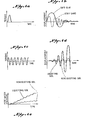
- a low amplitude test may be conducted initially. For example, an impulse torque of low amplitude may be applied to the cylinder 20 so that it rotates through a short arc of motion. The applied torque and response of the cylinder 20, as indicated in Figure 4b, as well as the response of cylinder 22 and the soil are thereafter measured and recorded at the computational stand 12.
- a high amplitude test may be conducted, for example to determine liquefaction resistance. In the liquefaction test, the inner cylinder 20 is excited by a sine wave or other oscillation at high amplitude, as indicated in Figure 4c.
- the response of the cylinder 20 and the pore water pressure are recorded, as indicated in Figures 4d and 4e, as are the response of cylinder 22 and the total stress.
- an impulse loading at high amplitude may be used to determine the nonlinear shearing stress-strain behavior of the soil sample.
- the torque applied to the drive shaft 34 by the drive system 28 may be determined by the torsional load cell 40 and the rotations of cylinders 20 and 22 measured by the motion sensors 36 or 38. Additional related information may be obtained from the pore water pressure transducers 98, as indicated in Figure 4e and total stress sensors 96.
- the properties of the soil tested may be inferred using appropriate analytical models of a test. However, properties may also be inferred using correlations with prior test data, or past observed field performance.
- analytical models a set of soil properties is assumed for the model. The test is simulated by applying to the model as is appropriate the measured excitation history of the actual test of interest or the initial portion of the measured motion history. The responses are computed for the model and compared to the responses recorded for the test of interest. If the responses measured in the field test compare within acceptable tolerances to the responses computed from the analytical model, then it may be concluded that the assumed properties of the model are a reasonable representation of the properties of the soil in situ.
- This analytical calculation may be computed automatically on site at the computation stand 12 and the user may be provided with an appropriate indication of general agreement, or the computations may be performed at a remote location at a later time. If agreement within an acceptable tolerance is not obtained, then an appropriate set of new properties is assumed for the model and the test is again simulated. Again, comparisons are made between results from analysis and field tests. This process is repeated until an acceptable comparison is achieved.
Landscapes
- Engineering & Computer Science (AREA)
- Life Sciences & Earth Sciences (AREA)
- Civil Engineering (AREA)
- Analytical Chemistry (AREA)
- General Life Sciences & Earth Sciences (AREA)
- Mining & Mineral Resources (AREA)
- Paleontology (AREA)
- Chemical & Material Sciences (AREA)
- General Engineering & Computer Science (AREA)
- Structural Engineering (AREA)
- Soil Sciences (AREA)
- Investigation Of Foundation Soil And Reinforcement Of Foundation Soil By Compacting Or Drainage (AREA)
- Investigating Strength Of Materials By Application Of Mechanical Stress (AREA)
- Excavating Of Shafts Or Tunnels (AREA)
- Sampling And Sample Adjustment (AREA)
- Road Paving Structures (AREA)
- Conveying And Assembling Of Building Elements In Situ (AREA)
- Casting Support Devices, Ladles, And Melt Control Thereby (AREA)
- Waste-Gas Treatment And Other Accessory Devices For Furnaces (AREA)
Abstract
Description
- This invention relates generally to techniques for testing soils, and particularly to techniques for testing soils involving the application of disturbances to an object embedded in the soil to evaluate the response of the object and the soil to such loading.
- It is often important to determine, at least by estimate, the resistance of a soil to liquefaction, the degradation characteristics of a soil, the dynamic shear modulus of a soil at low levels of shear deformation and the variation in the dynamic shear modulus of a soil with shear deformation. Liquefaction is the total loss of the stiffness and strength of a saturated soil, caused by increased pore water pressure which can result from cyclic loading. Degradation is the reduction in stiffness also due to the buildup of pore water pressure caused by cyclic loading. Degradation may or may not lead to liquefaction depending on the type and state of the soil. The shear modulus is basically the shearing stiffness of a soil. Generally, the shear modulus of a soil is a function of shearing deformation. For example, most soils show reduced stiffness with increasing deformation under monotonically increasing loading.
- Commonly these properties are necessary for analyses which predict the response of a site or foundation-structure system to dynamic loading caused by earthquakes, ocean waves or mechanical vibrations. Conventionally, these properties have been determined by conducting laboratory tests on samples recovered from a site or by in situ field tests.
- Laboratory testing of soil samples suffers from a number of problems. Particularly, the acts of recovering a sample, transporting it to a laboratory and preparing the sample for a test, can so disturb a sample from its original state, as to bring to question any results obtained. In addition, it is often difficult to reproduce the original field environment (state of stress) of the sample because it is often difficult and costly to define the environment and because typical laboratory test appa--ratus-are limited in their ability to reproduce environmental conditions. Because of the failure to precisely account for environmental considerations, laboratory tests are subject to error for this additional reason. Safely accounting for these disturbances and for environmental conditions may lead to excessively costly structures.
- The field testing of soils also suffers from a number of problems. Liquefaction resistance is generally tested in the field by a penetration test. Conventionally, a closed ended probe is either penetrated into the ground at a controlled slow rate, simulating static, non-cyclic loading but introducing severe failure into the local soil, or a cylinder is driven into the ground by violent impacts, also causing severe and immediate failure in the soil local to the cylinder. The resistance of the soil to liquefaction is correlated to the resistance of the probe or cylinder to penetration. Neither of these tests induces the type of loading generally induced by earthquakes or ocean waves which are the main known causes of liquefaction.
- Generally, earthquakes and ocean waves generate a lower amplitude loading which does not produce the magnitude of stresses needed for severe, immediate failure. Rather, the soil is excited at a lower amplitude of stress for a number of cycles. Generally, each cycle causes the soil to degrade incrementally and liquefaction is achieved only after a number of cycles. Hence, the phenomena induced by penetration tests are different from those of real interest, bringing into question the validity of the correlation of liquefaction resistance to penetration resistance.
- The fact that the desired loadings are not reproduced in penetration tests leads to other problems. For example, a number of common factors, such as age, state of stress, stress history, and the like, affect significantly liquefaction resistance as well as the resistance of an object to penetration. However, it is unlikely that these factors affect liquefaction resistance to the same degree that they affect the resistance to penetration. This brings into further question the validity of a correlation between liquefaction resistance and penetration resistance. As a result of such uncertainties, widely used correlations between liquefaction and penetration resistance are deliberately very conservative and can lead to costly designs for major structures.
- In addition, correlations are not available for all of the different types of soils which may be prone to liquefaction. Thus, there is even a greater uncertainty in estimating liquefaction resistance from penetration test results for a site consisting of soils with no significant testing history. A further drawback to in situ penetration testing is that this type of testing does not readily provide the type of information needed to conduct the refined analyses which are often necessary for site and foundation response studies.
- While in situ testing procedures have not been widely used to obtain degradation characteristics, a number of in situ tests have been used to determine the dynamic shear modulus and to a lesser extent, its variation with shear deformation. These include wave propagation tests, resonant footing tests and downhole probe tests. There are several different wave propagation techniques. With these techniques, the shear modulus of the soil is estimated from the measurement of some wave parameter, such as wave speed or wavelength. Each of these techniques has limitations or drawbacks. One technique, known as "seismic crosshole testing", requires two or more bore holes with sensors, and a below ground excitation source, making it relatively expensive for testing in a normal environment and difficult to practice in an offshore environment. A second technique, known as "seismic downhole testing", requires only one bore hole but is limited to measurements involving very low strain amplitude. A third technique, known as "seismic refraction", can result in poor definition of layering for sites where interbedded layers exist. A fourth technique, involving surface wave generation, requires sizeable equipment to provide definition of layering to the depths typically of interest.
- In resonant footing tests for obtaining dynamic shear modulus, a footing located at the surface is vibrated to determine its resonant frequency. With this procedure, only the near surface shear modulus can be estimated. It is usually desirable, however, to also obtain the below surface characteristics.
- There are several downhole probes for measuring` shear modulus. One probe measures the shear modulus of the walls of a bore hole. The material along the bore hole wall can be very disturbed due to the drilling activity, and may give results that are not representative of undisturbed soil. It is believed that with this technique, difficulties would be experienced in taking measurements in a cased bore hole. A second probe, disclosed in U.S. Patent 3,643,498 to Hardin, has similar capabilities and potential problems. Additionally, this probe may be penetrated below the base of the bore hole but this device probably would displace a considerable amount of the soil in the immediate vicinity of the measurement. Thus, the zone of soil having the greatest influence on measurements would probably be highly disturbed and therefore, to some degree, unrepresentative of the undisturbed soil.
- While the state of the technology in this field has -experienced rapid advancement, and many of the techniques now known have important advantages, the inventor of the present invention has identified certain characteristics that would be particularly advantageous if implemented in a single device. These characteristics include minimal soil disturbance by the testing probe, preservation of the original environment of the test soil, in situ testing using loading comparable to that experienced during the real life phenomena that induce soil failure, and the capability of providing liquefaction resistance, degradation characteristics, shear modulus, and the nonlinear variation in shear modulus with shear deformation. Further, it would be advantageous if such a device could readily enable the quantification of natural phenomena such as liquefaction and degradation.
- In accordance with one preferred embodiment of the present invention a method of testing soil includes the step of inserting a pair of concentric open ended cylinders into the soil to be tested. The inner of the cylinders is excited torsionally, resulting in its rotation through a limited arc of motion about its cylindrical axis. Measures of the resistance of the soil to the excitation of the inner cylinder are then obtained.
- In accordance with another preferred embodiment of the present invention, a soil testing probe includes a pair of concentric open ended cylinders. Means are provided for inserting the cylinders open ends first, into a soil sample to be tested. Means apply a torque to the inner of the cylinders which, in response, rotates through a limited arc of motion, within the sample, about the cylindrical axis. Thereafter, means are provided for obtaining measures of the resistance of the soil to the excitation of the inner cylinder.
- In accordance with still another preferred embodiment of the present invention, the soil testing probe may include an open ended, cylindrical device and means for inserting the device open end first into the soil sample to be tested. A torque is applied to the device which, in response, rotates through a limited arc of motion within the sample about its cylindrical axis. Thereafter, measuring means are provided for obtaining a measure of the torque applied by the soil in opposition to the rotational motion of the device, by measuring the response of the device to the torque applied by the applying means.
- In accordance with still another preferred embodiment of the present invention, a soil testing probe for making tests beneath the soil surface includes a rotatable open ended cylinder insertable into a soil sample to be tested. A concentric shield is positionable in close relationship to the upper portion of the open ended cylinder. Means are provided for rotating the cylinder with respect to the shield.
- In accordance with yet another preferred embodiment of the present invention, an apparatus for testing soil includes an open-ended probe insertable open end first into a soil sample to be tested. Means are provided for applying an oscillating force to the probe. Measuring means, give a measure of the resistance of the soil to the motion of the probe in response to the force.
-
- Figure 1 is a front elevational view of one embodiment of the present invention positioned at the bottom of the bore hole;
- Figure 2 is an enlarged, schematic cross-sectional view taken generally along the line 2-2 in Figure 1;
- Figure 3 is a greatly enlarged cross-sectional view taken generally along the line to 3-3 in Figure 1; and
- Figure 4 is a graphical depiction of typical testing excitations and responses.
- Referring to the drawing wherein like reference characters are used for like parts throughout the several views, a
soil testing apparatus 10 includes a control, recording, analysis and computation stand 12, areaction frame 14, arigid pipe 16, and aprobe 18. It should be understood that while the present invention is illustrated as being implemented by a rigid pipe apparatus, the present invention could also be implemented by a flexible wire line within a conventional drill string or in a variety of configurations for non-bore hole applications. The illustrated embodiment of the rigid pipe configuration provides for electrical communications between various sensors within theprobe 18 and thestand 12 and further permits a downward or upward displacement to be applied to theprobe 18 by way of thereaction frame 14 located at the surface. It should be understood that the displacement force could be applied by other conventional bore hole techniques used with a conventional drill string, and that a displacement force could be applied at the location of the probe, if desired, where a flexible wire line is used, instead of the rigid arrangement illustrated. Other embodiments also provide for electrical communications between various sensors withinprobe 18 and thestand 12. - As shown in Figure 2, the
probe 18 includes a pair of spacedconcentric cylinders surface compression unit 24, asensor section 26, adrive system 28, and anequipment chamber 32, all arranged in a stacked configuration so as to be insertable into a bore hole or other confined space. Theequipment chamber 32 may include conventional electronic equipment for providing signal communication between thestand 12,sensor section 26, anddrive system 28. Thedrive system 28 is conveniently a source of controllable torque or controllable angular displacement which is connected to adrive shaft 34 in turn connected to theinner cylinder 20. - In an embodiment using a conventional drill string, a connection system may be used to connect the
probe 18 to a drill bit. In this way, the forces needed to penetrate the probe into the ground and to remove it are transmitted through the drill string. This method permits the probe to be used without removal of any part of the drill string. A suitable connection system is shown in U.S. patent 3,709,031, hereby expressly incorporated by reference herein. - As shown in Figure 3, the
sensor section 26 includes a pair ofmotion transducers 36 and atorsional load cell 40. Thetorsional load cell 40, which may be implemented by a set of strain gauges, is arranged to measure the torque supplied through thedrive shaft 34 to theinner cylinder 20. Theload cell 40 may include a pair of sensors of different sensitivities for different testing amplitudes. The rotational response of thecylinder 20 to the excitation provided by thedrive system 28 is measured by themotion transducers 36. Advantageously, eachtransducer 36 includes a pair of sensors, one of which is a low sensitivity sensor for use in connection with high amplitudes and the other is a high sensitivity sensor for use with low amplitudes. Any rotational movement experienced by the relatively stationaryouter cylinder 22 is measured by themotion transducers 38. - The
electrical lines 42 from thetransducers 36 andload cell 40 and other sensors to be described hereinafter, cross between the rotatingdrive shaft extension 44 and =hestationary casing 46. Thus, brushes 48 are provided to insure continuity of electrical communication. In order to insure smooth rotation between rotating and non-rotating parts,bearings 50 are provided. - The
surface compression unit 24 includes an annular open toppedchamber 52 which is conveniently filled with a fluid, such as oil, indicated as 54. The exterior of theannular chamber 52 includes akey way 56 that rides along a helical key 58 on thecasing 46. Thus, movement of thechamber 52 along the central axis of theapparatus 10, is accompanied by the rotation ofchamber 52 about the central axis of theapparatus 10. The pressure within thechamber 52 may be adjusted by adding or withdrawing "hydraulic fluid through thefluid line 60. Since anannular opening 62 is provided in theextension 44, through which thefluid line 60 passes, fluid communication is always possible from thechamber 52 to the upward extension of thefluid line 60. - In response to the increase of fluid pressure within the
chamber 52, theannular chamber 52 rotates about a vertical axis on the helical key 58 by way of itskey way 56, threading downwardly towards the free end of theprobe 18. Advantageously, the lower face 64 of thechamber 52 is roughened. Further, apressure transducer 66 is contained in communication with thechamber 52 to provide feedback as to the pressure within thechamber 52. Thechamber 52 is sealed by anannular portion 68 of thecasing 46 which extends downwardly into thechamber 52 and includesannular seals 70 at abutting surfaces. - A
cylindrical shield 72 extends downwardly between theinner cylinder 20 and thesurface compression unit 24. Since thecylindrical shield 72 is connected to thecasing 46, it is relatively stationary and provides a concentric surface within which theinner cylinder 20 may rotate. Aseal 74 is provided at the lower end between theshield 72 andcylinder 20 to prevent the entry of soil and water into the frictionless zone between thecylinder 20 and theshield 72. - The
outer cylinder 22 is also fixed to thecasing 46 and is therefore relatively stationary. A plurality of outwardly extendingvanes 76 are distributed circumferentially about the exterior of thecylinder 22 and extend axially along the length of theapparatus 10 to further immobilize thecylinder 22. Thefree end 78 of theouter cylinder 22 is sharpened on its exterior side to aid in ground penetration and to minimize the disturbance of the test soil between the twocylinders - Since the
inner cylinder 20 may extend upwardly beyond thesurface compression unit 24, it may have a greater overall length in comparison to the portion of theouter cylinder 22 contacting the test soil. Particularly, afluid space 80 may be defined in the upper region of thecylinder 20. The upper extension of thespace 80 communicates by way of atube 81 which extends upwardly through theprobe 18 to an exit port (not shown). Theupper portion 82 of theinner cylinder 20 is recessed to adapt to thecylindrical shield 72. Thus, theinner cylinder 20 may be rotated by thedrive shaft 34 relative to thecylindrical shield 72. Theend portions 84 of theinner cylinder 20 include inwardly jutting, inwardly tapered cutting surfaces 86 to aid in ground penetration and also to minimize disturbances to the test soil. - Advantageously, the
interior surface 92 of theinner cylinder 20 has a low friction or low modulus lining, such as Teflon. Theexterior surface 94 may, if desired, include a roughened surface to increase frictional adherence between the soil and thesurface 94. - The inner and
outer cylinders total stress sensors 96 and porewater pressure transducers 98 inserted along their length. Thesensors 96 andtransducers 98 are contoured to preserve the cylindrical geometry. Wires may extend from these transducers upwardly through thecasing 46, ultimately connecting to theequipment chamber 32. Advantageously, thesensors 96 andtransducers 98 on thecylinders filter stone 102 may be provided on the upper end of theouter cylinder 22. Thestone 102 permits water trapped between theconcentric cylinder 22 and theinner cylinder 20 to escape during penetration. - The illustrated embodiment may be used in generally the following fashion. With the
probe 18 located just above the bottom of the bore hole, a downward force is applied by conventional techniques through thereaction frame 14 in order to insert thecylinders probe 18 is sufficiently slow to permit water trapped between the inner andouter cylinders stone 102 and for water trapped within theinner cylinder 20 to be expelled through thetube 81. - When the lower face 64 of the
surface compression unit 24 begins to contact the upper surface of the bottom of the bore hole, an initial back pressure is sensed by thepressure transducer 66 and is monitored through thecomputation stand 12. Then, with theprobe 18 fully inserted into the sample, as indicated by thepressure sensor 66 associated with thesurface compression unit 24, theprobe 18 is lifted slightly by thereaction frame 14. This relieves shear stresses and elastic deformations induced in the soil by penetration. The lower surface 64 is then pressed by thesurface compression unit 24 against the upper surface of the soil with a twisting motion so that any caps or peaks or other surface irregularities are sheared off and smoothed over. This enables the lower surface 64 to press against an even upper soil surface. The degree of pressure supplied by thesurface compression unit 24 may be adjusted by controlling the amount of fluid in thechamber 52. Theunit 24 supplies a desired degree of pressure to the upper surface of the soil in order to compensate for the loss of pressure due to the removal of soil from the bore hole. - The inwardly jutting tapered cutting surfaces 86 on the
inner cylinder 20 cause the soil, during insertion, to be funneled inwardly into the center region of theinner cylinder 20 and away from theinterior surface 92. This is desirable since the friction between the soil and theinner surface 92 should be as low as possible to minimize interaction between them. The freedom of the interior soil is aided by the provision of thefluid space 80 which prevents large confining pressures from developing within this soil. - At this time, one of a variety of excitations may be applied to the
inner cylinder 20 and the applied torque, the rotation of thecylinders various sensors computation stand 12. By virtue of theshield 72, the excitation is introduced at some depth below the surface of the test soil, thus minimizing effects of disturbances near this surface. In general, three types of limited arc, rotational perturbations of theinner cylinder 20 are advantageously provided by thedrive system 28. In a first type of loading, an impulse loading, the force distribution is broadly triangular, quickly increasing to a peak and then quickly dropping to zero. A second type of loading, termed initial condition loading, involves an initial rotary perturbation supplied, for example, from the energy stored within a set of springs (not shown) attached to thedrive shaft 34 and released by appropriate triggering action, conveniently fromstand 12. The motions that result from these initial perturbations slowly decay as energy is dissipated in the soil. The third type of loading involves a generally oscillating loading such as a sine wave wherein thedrive shaft 34 is rotated at a controlled amplitude of torque through a short arc of motion in one direction, reversed and rotated through a comparable arc of motion in the opposite direction. Alternatively, thedrive shaft 34 may be rotated at a controlled amplitude of angular displacement. The desired angular displacement is verified by themotion sensors 36 and the torque required to achieve the given angular displacement is measured by theload cell 40 and recorded at thestand 12. - Although the
outer cylinder 22 remains relatively stationary during testing, theouter cylinder 22 is important for liquefaction/degradation testing. The phenomena of liquefaction and degradation are induced primarily by the buildup of pore water pressures in the soil during cyclic loading. Without the impermeable boundary that theouter cylinder 22 provides, in the soils of greatest interest, water would be relatively free to flow away from the excited zone of soil near theinner cylinder 20 in response to increases in pore water pressures within-that-zone- Because of this potentially significant flow of water, pore water pressures may never approach values needed to cause liquefaction or severe degradation. Theouter cylinder 22, is also useful in achieving approximately constant volume conditions. - The following sequence of exemplary testing operations may be utilized. Referring to Figure 4a, a low amplitude test may be conducted initially. For example, an impulse torque of low amplitude may be applied to the
cylinder 20 so that it rotates through a short arc of motion. The applied torque and response of thecylinder 20, as indicated in Figure 4b, as well as the response ofcylinder 22 and the soil are thereafter measured and recorded at thecomputational stand 12. Next a high amplitude test may be conducted, for example to determine liquefaction resistance. In the liquefaction test, theinner cylinder 20 is excited by a sine wave or other oscillation at high amplitude, as indicated in Figure 4c. The response of thecylinder 20 and the pore water pressure are recorded, as indicated in Figures 4d and 4e, as are the response ofcylinder 22 and the total stress. Alternatively, instead of a sine wave loading, an impulse loading at high amplitude may be used to determine the nonlinear shearing stress-strain behavior of the soil sample. - After either high amplitude test is completed, it would generally be undesirable to perform any additional testing since the soil sample will be highly disturbed. However, other types of high amplitude or low amplitude excitations of any of the kinds discussed above may be applied in place of the specific examples described above.
- In the case of each test, the torque applied to the
drive shaft 34 by thedrive system 28 may be determined by thetorsional load cell 40 and the rotations ofcylinders motion sensors water pressure transducers 98, as indicated in Figure 4e andtotal stress sensors 96. - The properties of the soil tested may be inferred using appropriate analytical models of a test. However, properties may also be inferred using correlations with prior test data, or past observed field performance. When using analytical models,a set of soil properties is assumed for the model. The test is simulated by applying to the model as is appropriate the measured excitation history of the actual test of interest or the initial portion of the measured motion history. The responses are computed for the model and compared to the responses recorded for the test of interest. If the responses measured in the field test compare within acceptable tolerances to the responses computed from the analytical model, then it may be concluded that the assumed properties of the model are a reasonable representation of the properties of the soil in situ. This analytical calculation may be computed automatically on site at the
computation stand 12 and the user may be provided with an appropriate indication of general agreement, or the computations may be performed at a remote location at a later time. If agreement within an acceptable tolerance is not obtained, then an appropriate set of new properties is assumed for the model and the test is again simulated. Again, comparisons are made between results from analysis and field tests. This process is repeated until an acceptable comparison is achieved. - The comprehension of suitable analytical methodology is within the means of those skilled in the art. Also, correlation with prior test data may be used to infer properties of interest without using analytical models. The basis and application of appropriate fundamental analytical techniques are set forth, for example, in the article entitled "Torsional Dynamic Response of Solid Media" by Henke and Wylie in the Journal of the Engineering Mechanics Division, Proceedings of the American Society of Civil Engineers, Vol. 108, No. EM1, February 1982, hereby expressly incorporated herein and made a part hereof. Additional relevant information concerning analytical methodology is presented in the articles entitled "Fundamentals of Liquefaction Under Cyclic Loading" by Martin, et al., Journal of the Geotechnical Engineering Division, Proceedings of the American Society of Civil Engineers, Vol. 101, No. GT5, May, 1975; and "Nonlinear Behavior of Soft Clays During Cyclic Loading" by Idriss, et al., Journal of the Geotechnical Engineering Division, Proceedings of the American Society of Civil Engineers, Vol. 104, No. GT12, December, 1978. These articles are expressly incorporated herein and made a part hereof.
- A number of variations from the methods and apparatus as described herein are possible. Although the illustrated two cylinder embodiment has a number of important advantages, important achievements may be obtained without the use of two cylinders. In such a case, a single cylinder may be utilized, dispensing with the exterior cylinder. Althoughr such an arrangement may be less than optimal in determining liquefaction resistance and soil degradation characteristics, it may have important applications in determining shear modulus and its variation with shear deformation. Further, although the use of rotary perturbations are believed to be advantageous, other oscillating perturbations, such as vertically reciprocating perturbations, may be useful in certain contexts.
- While the present invention has been described with respect to a single preferred embodiment, those skilled in the art will appreciate a number of modifications and variations. It is intended to cover within the appended claims all such variations and modifications as come within the true spirit ard scope of the present invention.
Claims (11)
Priority Applications (1)
| Application Number | Priority Date | Filing Date | Title |
|---|---|---|---|
| AT85101908T ATE53875T1 (en) | 1984-03-06 | 1985-02-21 | METHOD AND DEVICE FOR TESTING THE SUB-SURFACE. |
Applications Claiming Priority (2)
| Application Number | Priority Date | Filing Date | Title |
|---|---|---|---|
| US06/586,799 US4594899A (en) | 1984-03-06 | 1984-03-06 | Method and apparatus for testing soil |
| US586799 | 1984-03-06 |
Publications (3)
| Publication Number | Publication Date |
|---|---|
| EP0154261A2 true EP0154261A2 (en) | 1985-09-11 |
| EP0154261A3 EP0154261A3 (en) | 1986-12-30 |
| EP0154261B1 EP0154261B1 (en) | 1990-05-02 |
Family
ID=24347147
Family Applications (1)
| Application Number | Title | Priority Date | Filing Date |
|---|---|---|---|
| EP85101908A Expired - Lifetime EP0154261B1 (en) | 1984-03-06 | 1985-02-21 | Method and apparatus for testing soil |
Country Status (9)
| Country | Link |
|---|---|
| US (1) | US4594899A (en) |
| EP (1) | EP0154261B1 (en) |
| JP (1) | JPS60203724A (en) |
| AT (1) | ATE53875T1 (en) |
| AU (1) | AU576824B2 (en) |
| CA (1) | CA1232155A (en) |
| DE (1) | DE3577461D1 (en) |
| NO (1) | NO165216C (en) |
| NZ (1) | NZ211299A (en) |
Families Citing this family (27)
| Publication number | Priority date | Publication date | Assignee | Title |
|---|---|---|---|---|
| CA1232535A (en) * | 1985-09-09 | 1988-02-09 | Robert Koopmans | Borehole dilatometer intensifier |
| US4760741A (en) * | 1986-02-03 | 1988-08-02 | Robert Koopmans | Borehole dilatometer with intensifier |
| CA1240851A (en) * | 1987-08-25 | 1988-08-23 | Gerhard H. Herget | Strain monitoring system |
| US4825700A (en) * | 1988-06-15 | 1989-05-02 | Regents Of The University Of Minnesota | Bi-axial geomaterial test system |
| US5109702A (en) * | 1990-06-27 | 1992-05-05 | The United States Of America As Represented By The Secretary Of The Air Force | Method for determining liquefaction potential of cohesionless soils |
| US5321976A (en) * | 1992-04-15 | 1994-06-21 | Dalrymple Donald D | Golf green test apparatus |
| FR2723785B1 (en) * | 1994-08-19 | 1996-11-15 | Etat Francais Laboratoire Cent | MEASURING DEVICE FOR EVALUATING INTERFACE PROPERTIES BETWEEN A SOLID MATERIAL AND A GRANULAR MATERIAL |
| US5739435A (en) * | 1995-10-31 | 1998-04-14 | Carnegie Institution Of Washington | Two-stage strain-sensing device and method |
| US6912903B2 (en) * | 1996-02-01 | 2005-07-05 | Bbnt Solutions Llc | Soil compaction measurement |
| AU1752497A (en) | 1996-02-01 | 1997-08-22 | Bolt Beranek And Newman Inc. | Soil compaction measurement |
| AU7819598A (en) * | 1997-06-11 | 1998-12-30 | Dynamic In Situ Geotechnical Testing Incorporated | Soil testing assemblies |
| NL1010178C2 (en) * | 1998-09-24 | 2000-03-27 | Berg A P Van Den Beheer Bv | CPT device and method for operating it. |
| GB0028645D0 (en) * | 2000-11-24 | 2001-01-10 | Univ Cranfield | A handheld measurement device for the determination of racecourse going |
| US6615653B1 (en) * | 2001-09-27 | 2003-09-09 | Geosierra, Llc | In situ method for determining soil liquefaction tendency and its prevention by electro-osmosis |
| WO2005012866A2 (en) * | 2003-07-30 | 2005-02-10 | Bbnt Solutions Llc | Soil compaction measurement on moving platform |
| CN100529273C (en) * | 2003-12-26 | 2009-08-19 | 株式会社益田技建 | Testing method and apparatus ground liquefaction and dynamic characteristics in original position utilizing boring hole |
| US7183779B2 (en) * | 2004-12-28 | 2007-02-27 | Spectrum Technologies, Inc. | Soil probe device and method of making same |
| EP2307622A2 (en) * | 2008-05-01 | 2011-04-13 | David C. Paul | Form for a concrete footing |
| US8561475B2 (en) | 2011-03-18 | 2013-10-22 | Bruce David Johnson | Method and apparatus for investigating mechanical properties of soft materials |
| US20140219726A1 (en) * | 2011-06-15 | 2014-08-07 | Alexander Degen | Method for ground probing |
| CN102608294B (en) * | 2012-03-29 | 2015-01-28 | 上海化工研究院 | Temperature difference transpiration type soil composition leaching testing device |
| JP5526290B1 (en) * | 2013-04-02 | 2014-06-18 | 報国エンジニアリング株式会社 | Sampling apparatus and method for liquefaction determination |
| JP6449075B2 (en) * | 2015-03-26 | 2019-01-09 | 基礎地盤コンサルタンツ株式会社 | Sounding test method and sounding test apparatus |
| IT201800002647A1 (en) * | 2018-02-13 | 2019-08-13 | Univ Degli Studi Di Milano Bicocca | DEVICE AND METHOD FOR SIMULATION OF INJECTIONS OF CEMENTITIOUS AND / OR CHEMICAL MIXTURES IN SOILS |
| EP3533932B1 (en) * | 2018-03-01 | 2020-07-15 | BAUER Spezialtiefbau GmbH | Method and system for creating a foundation element in the ground |
| RU2711261C1 (en) * | 2019-05-17 | 2020-01-15 | Акционерное общество "Научно-исследовательский центр "Строительство", АО "НИЦ "Строительство" | Soil testing method by means of static probing method |
| CN114279856B (en) * | 2021-12-27 | 2024-06-11 | 东北大学 | Huke pressure chamber for directly obtaining circumferential deformation of rock sample and facilitating replacement of rock sample |
Citations (6)
| Publication number | Priority date | Publication date | Assignee | Title |
|---|---|---|---|---|
| DE508711C (en) * | 1930-10-01 | Forschungsgesellschaft Fuer Bo | Strength tester for the shear strength of the subsoil | |
| GB771540A (en) * | 1955-09-06 | 1957-04-03 | Nat Res Dev | Improvements relating to the measurement of soil strength |
| US2993367A (en) * | 1958-12-19 | 1961-07-25 | Raymond Int Inc | Apparatus for shear testing of soil |
| US3643498A (en) * | 1970-07-27 | 1972-02-22 | Bobby O Hardin | Apparatus for testing soils in situ |
| US4353247A (en) * | 1981-01-02 | 1982-10-12 | Rodolfo De Domenico | Method and equipment for the in situ determination of geotechnical parameters of a sandy soil |
| US4400970A (en) * | 1981-09-24 | 1983-08-30 | Ali Muhammad A | Method of and apparatus for measuring in situ, the sub-surface bearing strength, the skin friction, and other sub-surface characteristics of the soil |
Family Cites Families (11)
| Publication number | Priority date | Publication date | Assignee | Title |
|---|---|---|---|---|
| US2303162A (en) * | 1940-08-13 | 1942-11-24 | Carter Coal Company | Apparatus for measuring thixotropy |
| US2603967A (en) * | 1947-09-05 | 1952-07-22 | Carlson Lyman Otto Theodore | Apparatus for measuring the torsional shear strength of soil |
| US2709363A (en) * | 1953-07-27 | 1955-05-31 | Foundation Company Of Canada L | Apparatus for determining the torsional shear strength of soil |
| US3435666A (en) * | 1966-07-18 | 1969-04-01 | Champion Lab Inc | Viscometer |
| US3465576A (en) * | 1966-10-14 | 1969-09-09 | Us Army | Soil shear deformation tester |
| NL6708390A (en) * | 1967-06-16 | 1968-12-17 | ||
| US3709031A (en) * | 1970-07-02 | 1973-01-09 | S Wilson | Means for determining the shear strength of earth in situ |
| SU586369A1 (en) * | 1973-02-26 | 1977-12-30 | Волгоградский Политехнический Институт | Measuring unit of rotary bell-type viscosimeter |
| SU616561A1 (en) * | 1977-01-12 | 1978-07-25 | Ростовский-на-Дону научно-исследовательский институт технологии машиностроения | Rotary viscosimeter |
| US4274283A (en) * | 1978-10-16 | 1981-06-23 | Exxon Production Research Company | Apparatus and method for measuring fluid gel strength |
| US4302967A (en) * | 1979-05-30 | 1981-12-01 | Dufey Victor A | Apparatus for measuring the mechanical characteristics of a body |
-
1984
- 1984-03-06 US US06/586,799 patent/US4594899A/en not_active Expired - Lifetime
-
1985
- 1985-02-08 CA CA000473961A patent/CA1232155A/en not_active Expired
- 1985-02-21 AT AT85101908T patent/ATE53875T1/en active
- 1985-02-21 EP EP85101908A patent/EP0154261B1/en not_active Expired - Lifetime
- 1985-02-21 DE DE8585101908T patent/DE3577461D1/en not_active Expired - Lifetime
- 1985-02-28 AU AU39254/85A patent/AU576824B2/en not_active Ceased
- 1985-03-04 NZ NZ211299A patent/NZ211299A/en unknown
- 1985-03-05 NO NO850877A patent/NO165216C/en not_active IP Right Cessation
- 1985-03-06 JP JP60042762A patent/JPS60203724A/en active Granted
Patent Citations (6)
| Publication number | Priority date | Publication date | Assignee | Title |
|---|---|---|---|---|
| DE508711C (en) * | 1930-10-01 | Forschungsgesellschaft Fuer Bo | Strength tester for the shear strength of the subsoil | |
| GB771540A (en) * | 1955-09-06 | 1957-04-03 | Nat Res Dev | Improvements relating to the measurement of soil strength |
| US2993367A (en) * | 1958-12-19 | 1961-07-25 | Raymond Int Inc | Apparatus for shear testing of soil |
| US3643498A (en) * | 1970-07-27 | 1972-02-22 | Bobby O Hardin | Apparatus for testing soils in situ |
| US4353247A (en) * | 1981-01-02 | 1982-10-12 | Rodolfo De Domenico | Method and equipment for the in situ determination of geotechnical parameters of a sandy soil |
| US4400970A (en) * | 1981-09-24 | 1983-08-30 | Ali Muhammad A | Method of and apparatus for measuring in situ, the sub-surface bearing strength, the skin friction, and other sub-surface characteristics of the soil |
Also Published As
| Publication number | Publication date |
|---|---|
| US4594899A (en) | 1986-06-17 |
| AU576824B2 (en) | 1988-09-08 |
| DE3577461D1 (en) | 1990-06-07 |
| AU3925485A (en) | 1985-09-12 |
| NO165216C (en) | 1991-01-09 |
| NO850877L (en) | 1985-09-09 |
| NZ211299A (en) | 1987-04-30 |
| EP0154261B1 (en) | 1990-05-02 |
| ATE53875T1 (en) | 1990-06-15 |
| CA1232155A (en) | 1988-02-02 |
| JPS60203724A (en) | 1985-10-15 |
| EP0154261A3 (en) | 1986-12-30 |
| NO165216B (en) | 1990-10-01 |
| JPH0369406B2 (en) | 1991-11-01 |
Similar Documents
| Publication | Publication Date | Title |
|---|---|---|
| US4594899A (en) | Method and apparatus for testing soil | |
| Holeyman | Keynote lecture: Technology of pile dynamic testing | |
| Robertson | In situ testing and its application to foundation engineering | |
| Finno et al. | Impulse response evaluation of drilled shafts | |
| EP0490420A2 (en) | Downhole penetrometer | |
| Blaney et al. | Measured lateral response of mass on single pile in clay | |
| US6431006B1 (en) | Soil testing assemblies | |
| US7753118B2 (en) | Method and tool for evaluating fluid dynamic properties of a cement annulus surrounding a casing | |
| Robertson | In-situ testing of soil with emphasis on its application to liquefaction assessment | |
| US5109702A (en) | Method for determining liquefaction potential of cohesionless soils | |
| Aubeny et al. | Effects of disturbance on undrained strengths interpreted from pressuremeter tests | |
| Whittle | Assessment of an effective stress analysis for predicting the performance of driven piles in clays | |
| Prevost et al. | Dynamic soil-structure interaction: centrifugal modeling | |
| Henke et al. | Laboratory evaluation of in situ geotechnical torsional cylindrical impulse shear test for earthquake resistant design | |
| De Alba | Pile settlement in liquefying sand deposit | |
| JP4115216B2 (en) | In-hole vertical loading test method and apparatus | |
| JP2571419B2 (en) | In-hole loading test device using elastic body | |
| Lacasse et al. | Interpretation of self-boring and push-in pressuremeter tests | |
| Gle et al. | Suggested procedure for conducting dynamic lateral-load tests on piles | |
| Dano et al. | Interpretation of dilatometer tests in a heavy oil reservoir | |
| Reese | Design and evaluation of load tests on deep foundations | |
| CA2009349C (en) | Method and device for in-situ determination of rheological properties of earth materials | |
| JPH03260212A (en) | Rotary drill bit pressure variable type ground strength measuring method and apparatus | |
| SU1148924A1 (en) | Apparatus for determining deformation properties of foundation soils at a depth | |
| Elton | Settlement of footings on sand by CPT data |
Legal Events
| Date | Code | Title | Description |
|---|---|---|---|
| PUAI | Public reference made under article 153(3) epc to a published international application that has entered the european phase |
Free format text: ORIGINAL CODE: 0009012 |
|
| AK | Designated contracting states |
Designated state(s): AT BE CH DE FR GB IT LI LU NL SE |
|
| PUAL | Search report despatched |
Free format text: ORIGINAL CODE: 0009013 |
|
| AK | Designated contracting states |
Kind code of ref document: A3 Designated state(s): AT BE CH DE FR GB IT LI LU NL SE |
|
| 17P | Request for examination filed |
Effective date: 19870626 |
|
| 17Q | First examination report despatched |
Effective date: 19881202 |
|
| GRAA | (expected) grant |
Free format text: ORIGINAL CODE: 0009210 |
|
| AK | Designated contracting states |
Kind code of ref document: B1 Designated state(s): AT BE CH DE FR GB IT LI LU NL SE |
|
| REF | Corresponds to: |
Ref document number: 53875 Country of ref document: AT Date of ref document: 19900615 Kind code of ref document: T |
|
| ITF | It: translation for a ep patent filed | ||
| REF | Corresponds to: |
Ref document number: 3577461 Country of ref document: DE Date of ref document: 19900607 |
|
| ET | Fr: translation filed | ||
| ITTA | It: last paid annual fee | ||
| PLBE | No opposition filed within time limit |
Free format text: ORIGINAL CODE: 0009261 |
|
| STAA | Information on the status of an ep patent application or granted ep patent |
Free format text: STATUS: NO OPPOSITION FILED WITHIN TIME LIMIT |
|
| 26N | No opposition filed | ||
| EPTA | Lu: last paid annual fee | ||
| EAL | Se: european patent in force in sweden |
Ref document number: 85101908.3 |
|
| PGFP | Annual fee paid to national office [announced via postgrant information from national office to epo] |
Ref country code: AT Payment date: 19960213 Year of fee payment: 12 |
|
| PGFP | Annual fee paid to national office [announced via postgrant information from national office to epo] |
Ref country code: SE Payment date: 19960215 Year of fee payment: 12 |
|
| PGFP | Annual fee paid to national office [announced via postgrant information from national office to epo] |
Ref country code: NL Payment date: 19960229 Year of fee payment: 12 |
|
| PGFP | Annual fee paid to national office [announced via postgrant information from national office to epo] |
Ref country code: LU Payment date: 19960301 Year of fee payment: 12 |
|
| PGFP | Annual fee paid to national office [announced via postgrant information from national office to epo] |
Ref country code: CH Payment date: 19960314 Year of fee payment: 12 |
|
| PGFP | Annual fee paid to national office [announced via postgrant information from national office to epo] |
Ref country code: BE Payment date: 19960412 Year of fee payment: 12 |
|
| PG25 | Lapsed in a contracting state [announced via postgrant information from national office to epo] |
Ref country code: LU Free format text: LAPSE BECAUSE OF NON-PAYMENT OF DUE FEES Effective date: 19970221 Ref country code: AT Effective date: 19970221 |
|
| PG25 | Lapsed in a contracting state [announced via postgrant information from national office to epo] |
Ref country code: SE Effective date: 19970222 |
|
| PG25 | Lapsed in a contracting state [announced via postgrant information from national office to epo] |
Ref country code: LI Effective date: 19970228 Ref country code: CH Effective date: 19970228 Ref country code: BE Effective date: 19970228 |
|
| BERE | Be: lapsed |
Owner name: HENKE WANDA K. Effective date: 19970228 Owner name: HENKE ROBERT Effective date: 19970228 |
|
| PG25 | Lapsed in a contracting state [announced via postgrant information from national office to epo] |
Ref country code: NL Effective date: 19970901 |
|
| REG | Reference to a national code |
Ref country code: CH Ref legal event code: PL |
|
| EUG | Se: european patent has lapsed |
Ref document number: 85101908.3 |
|
| NLV4 | Nl: lapsed or anulled due to non-payment of the annual fee |
Effective date: 19970901 |
|
| PGFP | Annual fee paid to national office [announced via postgrant information from national office to epo] |
Ref country code: GB Payment date: 20010104 Year of fee payment: 17 |
|
| PGFP | Annual fee paid to national office [announced via postgrant information from national office to epo] |
Ref country code: FR Payment date: 20010201 Year of fee payment: 17 |
|
| PGFP | Annual fee paid to national office [announced via postgrant information from national office to epo] |
Ref country code: DE Payment date: 20010228 Year of fee payment: 17 |
|
| REG | Reference to a national code |
Ref country code: GB Ref legal event code: IF02 |
|
| PG25 | Lapsed in a contracting state [announced via postgrant information from national office to epo] |
Ref country code: GB Free format text: LAPSE BECAUSE OF NON-PAYMENT OF DUE FEES Effective date: 20020221 |
|
| PG25 | Lapsed in a contracting state [announced via postgrant information from national office to epo] |
Ref country code: DE Free format text: LAPSE BECAUSE OF NON-PAYMENT OF DUE FEES Effective date: 20020903 |
|
| GBPC | Gb: european patent ceased through non-payment of renewal fee |
Effective date: 20020221 |
|
| PG25 | Lapsed in a contracting state [announced via postgrant information from national office to epo] |
Ref country code: FR Free format text: LAPSE BECAUSE OF NON-PAYMENT OF DUE FEES Effective date: 20021031 |
|
| REG | Reference to a national code |
Ref country code: FR Ref legal event code: ST |