EP0154257A2 - Device for producing a perforated plastics sheet - Google Patents
Device for producing a perforated plastics sheet Download PDFInfo
- Publication number
- EP0154257A2 EP0154257A2 EP85101860A EP85101860A EP0154257A2 EP 0154257 A2 EP0154257 A2 EP 0154257A2 EP 85101860 A EP85101860 A EP 85101860A EP 85101860 A EP85101860 A EP 85101860A EP 0154257 A2 EP0154257 A2 EP 0154257A2
- Authority
- EP
- European Patent Office
- Prior art keywords
- screen surface
- end rings
- cylindrical
- suction box
- plastic film
- Prior art date
- Legal status (The legal status is an assumption and is not a legal conclusion. Google has not performed a legal analysis and makes no representation as to the accuracy of the status listed.)
- Withdrawn
Links
Images
Classifications
-
- B—PERFORMING OPERATIONS; TRANSPORTING
- B26—HAND CUTTING TOOLS; CUTTING; SEVERING
- B26F—PERFORATING; PUNCHING; CUTTING-OUT; STAMPING-OUT; SEVERING BY MEANS OTHER THAN CUTTING
- B26F1/00—Perforating; Punching; Cutting-out; Stamping-out; Apparatus therefor
- B26F1/26—Perforating by non-mechanical means, e.g. by fluid jet
-
- B—PERFORMING OPERATIONS; TRANSPORTING
- B29—WORKING OF PLASTICS; WORKING OF SUBSTANCES IN A PLASTIC STATE IN GENERAL
- B29C—SHAPING OR JOINING OF PLASTICS; SHAPING OF MATERIAL IN A PLASTIC STATE, NOT OTHERWISE PROVIDED FOR; AFTER-TREATMENT OF THE SHAPED PRODUCTS, e.g. REPAIRING
- B29C59/00—Surface shaping of articles, e.g. embossing; Apparatus therefor
- B29C59/02—Surface shaping of articles, e.g. embossing; Apparatus therefor by mechanical means, e.g. pressing
- B29C59/06—Surface shaping of articles, e.g. embossing; Apparatus therefor by mechanical means, e.g. pressing using vacuum drums
Definitions
- the invention relates to a device for producing a perforated and possibly an embossed plastic film .. with a one-piece cylindrical screen surface on which the perforation and possibly the embossing of the film takes place, the plastic film directly on the screen surface or at least approximately in between Screen surface and a counter roll formed gap is extruded.
- the screen surface is arranged on a cylinder which consists of a support frame with axially extending strips on which the screen surface is supported. These strips are imaged on the plastic film when perforating under vacuum; which means that there is no perforation in the area of the strips.
- the object of the invention is to create a device with which a completely web-free perforation is possible.
- the cylindrical sieve surface is fixed in a rotationally fixed manner only with its two ends on disc-shaped end rings, that both end rings with drives are connected, which run synchronously to one another, and that a suction box extending at least approximately over the entire axial length of the screen surface is arranged within the cylindrical screen surface, on the two sealing strips facing the screen surface of which it can be supported, the suction box being fastened to two side frames, which carry the drive parts and the two disc-shaped end rings, which are pulled apart via spring elements which act on one of these end rings in such a way that an axial tensile stress is established in the screen surface.
- the film perforated in this way has an absolutely uniform perforation pattern.
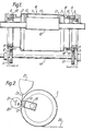
- the perforating device shown in Fig. 1 has an endless cylindrical screen surface 1, which is attached with its two end portions on disc-shaped end rings 2 and 3 rotatably. These two end rings are rotatably supported by ball bearings 4 and 5 on a side frame 6 and 7, respectively.
- the outer rings 8 and 9 of the two ball bearings 4 and 5 are equipped with teeth 10 and 11, in each of which a drive gear 12 or 13 engages. These two drive gears sit on a common drive shaft 14, which ensures that the two end rings 2 and 3 are driven synchronously with each other.
- a suction box 15 is arranged within the perforating device and is mounted on both side frames 6 and 7. On its side facing the sieve surface 1, the suction box is provided with a suction opening 16 which is formed by four sealing strips 17. The inside of the screen surface 1 is supported on these sealing strips 17.
- the end ring 3 is axially displaceably mounted on bolts 18 which are fastened to the outer ring 9 of the ball bearing 5. Between the heads of these bolts 18 and the end ring 3, compression springs 19 are clamped, which push the end ring 3 in the direction of the ball bearing 5 and thus away from the other end ring 2. This sets a tensile stress in the screen surface 1, which stiffens it.
- a counter roller 20 is arranged on the outside of the screen surface 1, opposite the sealing strips 17, the position of which can be changed along the arrow 21, as a result of which the free size of the suction opening 16 can be adjusted.
- An extruder nozzle 22 is arranged above the screen surface 1, from which a plastic film 23 is extruded into the gap formed between the screen surface 1 and the counter roller 20.
- the plastic film 23 can hit the screen surface or the counter roller slightly before the gap. Due to the suction effect, the plastic film 23 is perforated in the area of the suction opening and, depending on the design of the screen surface and possibly the counter roller, is additionally embossed. As a finished perforated and possibly embossed film, it is then removed from the screen surface.
Abstract
Description
Die Erfindung betrifft eine Einrichtung zum Herstellen einer perforierten und evtl. einer geprägten Kunststoffolie,..mit einer einstückigen zylinderförmigen Siebfläche, auf welcher die Perforierung und evtl. die Prägung der Folie erfolgt, wobei die Kunststoffolie unmittelbar auf die Siebfläche oder wenigstens annähernd in den zwischen Siebfläche und einer Gegenwalze gebildeten Spalt extrudiert wird.The invention relates to a device for producing a perforated and possibly an embossed plastic film .. with a one-piece cylindrical screen surface on which the perforation and possibly the embossing of the film takes place, the plastic film directly on the screen surface or at least approximately in between Screen surface and a counter roll formed gap is extruded.
Bei bekannten Einrichtungen dieser Art ist die Siebfläche auf einem Zylinder angeordnet, der aus einem Stützgerippe mit axial verlaufenden Leisten, auf denen sich die Siebfläche abstützt, besteht. Diese Leisten werden beim Perforieren unter Vacuum auf der Kunststoffolie abgebildet; was bedeutet, daß im Bereich der Leisten keine Perforierung stattfindet.In known devices of this type, the screen surface is arranged on a cylinder which consists of a support frame with axially extending strips on which the screen surface is supported. These strips are imaged on the plastic film when perforating under vacuum; which means that there is no perforation in the area of the strips.
Dies ist in vielen Fällen unerwünscht, weshalb der Erfindung die Aufgabe zugrunde liegt, eine Einrichtung zu schaffen, mit der eine völlig stegfreie Perforation möglich ist.This is undesirable in many cases, which is why the object of the invention is to create a device with which a completely web-free perforation is possible.
Diese Aufgabe wird erfindungsgemäß dadurch gelöst, daß die zylinderförmig ausgebildet Siebfläche lediglich mit ihren beiden stirnseitigen Enden auf scheibenförmigen Endringen drehfest befestigt ist, daß beide Endringe mit Antrieben verbunden sind, die synchron zueinander laufen, und daß innerhalb der zylinderförmigen Siebfläche ein wenigstens annähernd über die ganze axiale Länge der Siebfläche reichender Saugkasten angeordnet ist, auf dessen beiden der Siebfläche zugekehrten Dichtleisten sich diese abzustützen vermag, wobei der Saugkasten an zwei Seitenstuhlungen befestigt ist, welche die Antriebsteile und die beiden scheibenförmigen Endringe tragen, die über Federelemente, welche an einem dieser Endringe angreifen, derart auseinandergezogen sind, daß sich in der Siebfläche eine axiale Zugspannung einstellt.This object is achieved in that the cylindrical sieve surface is fixed in a rotationally fixed manner only with its two ends on disc-shaped end rings, that both end rings with drives are connected, which run synchronously to one another, and that a suction box extending at least approximately over the entire axial length of the screen surface is arranged within the cylindrical screen surface, on the two sealing strips facing the screen surface of which it can be supported, the suction box being fastened to two side frames, which carry the drive parts and the two disc-shaped end rings, which are pulled apart via spring elements which act on one of these end rings in such a way that an axial tensile stress is established in the screen surface.
Hierdurch wird erreicht, daß die Perforierung der Folie ausschließlich durch die Öffnungen in der Siebfläche erzielt wird, so daß Unterbrechungen völlig ausscheiden. Die so perforierte Folie weist ein absolut gleichmäßiges Lochmuster auf.This ensures that the perforation of the film is achieved exclusively through the openings in the screen surface, so that interruptions are completely eliminated. The film perforated in this way has an absolutely uniform perforation pattern.
In der Zeichnung ist ein Ausführungsbeispiel einer erfindungsgemäßen Einrichtung dargestellt. Dabei zeigen:
- Fig. 1 einen Längsschnitt durch eine zylinderförmige Perforiereinrichtung und
- Fig. 2 einen Querschnitt durch diese Einrichtung.
- Fig. 1 shows a longitudinal section through a cylindrical perforating device and
- Fig. 2 shows a cross section through this device.
Die in Fig. 1 dargestellte Perforiereinrichtung hat eine endlose zylindrische Siebfläche 1, die mit ihren beiden stirnseitigen Endabschnitten auf scheibenförmigen Endringen 2 und 3 drehfest befestigt ist. Diese beiden Endringe sind über Kugellager 4 und 5 drehbar an jeweils einer Seitenstuhlung 6 bzw. 7 gelagert. Die Außenringe 8 und 9 der beiden Kugellager 4 und 5 sind mit einer Verzahnung 10 bzw. 11 ausgerüstet, in die jeweils ein Antriebszahnrad 12 bzw. 13 eingreift. Diese beiden Antriebszahnräder sitzen auf einer gemeinsamen Antriebswelle 14, wodurch gewährleistet ist, daß die beiden Endringe 2 und 3 synchron zueinander angetrieben werden.The perforating device shown in Fig. 1 has an endless cylindrical screen surface 1, which is attached with its two end portions on disc-
Innerhalb der Perforiereinrichtung ist ein Saugkasten 15 angeordnet, der an beiden Seitenstuhlungen 6 und 7 gelagert ist. An seiner der Siebfläche 1 zugekehrten Seite ist der Saugkasten mit einer Saugöffnung 16 versehen, die durch vier Dichtleisten 17 gebildet ist. Auf diesen Dichtleisten 17 stützt sich die Siebfläche 1 mit ihrer Innenseite ab. Der Endring 3 ist axial verschiebbar auf Bolzen 18 gelagert, die am Außenring 9 des Kugellagers 5 befestigt sind. Zwischen den Köpfen dieser Bolzen 18 und dem Endring 3 sind Druckfedern 19 eingespannt, die den Endring 3 in Richtung auf das Kugellager 5 und damit vom anderen Endring 2 wegdrücken. Damit wird in der Siebfläche 1 eine Zugspannung eingestellt, welche diese versteift.A
Wie aus Fig. 2 ersichtlich, ist an der Außenseite der Siebfläche 1, den Dichtleisten 17 gegenüberliegend, eine Gegenwalze 20 angeordnet, deren Lage entlang des Pfeiles 21 veränderbar ist, wodurch die freie Größe der Saugöffnung 16 einstellbar ist. Oberhalb der Siebfläche 1 ist eine Extruderdüse 22 angeordnet, aus der eine Kunststoffolie 23 in den zwischen der Siebfläche 1 und der Gegenwalze 20 gebildeten Spalt extrudiert wird. Die Kunststoffolie 23 kann jedoch geringfügig vor dem Spalt auf die Siebfläche oder die Gegenwalze auftreffen. Durch die Saugwirkung wird die Kunststofffolie 23 im Bereich der Saugöffnung perforiert und je nach Ausgestaltung der Siebfläche und evtl. der Gegenwalze noch zusätzlich geprägt. Als fertige perforierte und evtl. geprägte Folie wird sie dann von der Siebfläche abgenommen.As can be seen from FIG. 2, a counter roller 20 is arranged on the outside of the screen surface 1, opposite the
Claims (1)
Applications Claiming Priority (2)
| Application Number | Priority Date | Filing Date | Title |
|---|---|---|---|
| DE3407318 | 1984-02-29 | ||
| DE19843407318 DE3407318C1 (en) | 1984-02-29 | 1984-02-29 | Roller for producing a perforated and possibly embossed plastic film |
Publications (2)
| Publication Number | Publication Date |
|---|---|
| EP0154257A2 true EP0154257A2 (en) | 1985-09-11 |
| EP0154257A3 EP0154257A3 (en) | 1985-11-06 |
Family
ID=6229126
Family Applications (1)
| Application Number | Title | Priority Date | Filing Date |
|---|---|---|---|
| EP85101860A Withdrawn EP0154257A3 (en) | 1984-02-29 | 1985-02-21 | Device for producing a perforated plastics sheet |
Country Status (3)
| Country | Link |
|---|---|
| EP (1) | EP0154257A3 (en) |
| JP (1) | JPS60204305A (en) |
| DE (1) | DE3407318C1 (en) |
Families Citing this family (2)
| Publication number | Priority date | Publication date | Assignee | Title |
|---|---|---|---|---|
| DE19524076C1 (en) * | 1995-07-01 | 1996-10-24 | Hcd Gmbh | Roller-moulding fine fibrous velour finish on surface of extruded thermoplastic sheet |
| EP2928666B1 (en) * | 2012-12-05 | 2020-05-27 | Tredegar Film Products Corporation | Method for providing micro-aberrations on a film |
Citations (3)
| Publication number | Priority date | Publication date | Assignee | Title |
|---|---|---|---|---|
| US3709647A (en) * | 1970-10-21 | 1973-01-09 | Clear Pack Co | Apparatus for forming an embossed thermoplastic sheet |
| DE2403918A1 (en) * | 1973-02-07 | 1974-08-22 | Satoshi Kawakami | DEVICE FOR THE CONTINUOUS PRODUCTION OF LAMINATED UPHOLSTERY FROM THERMOPLASTIC MATERIAL |
| DE2927719A1 (en) * | 1978-07-10 | 1980-01-24 | Ethyl Corp | DEVICE FOR PRINTING AND / OR PERFORATING THERMOPLASTIC FILMS |
-
1984
- 1984-02-29 DE DE19843407318 patent/DE3407318C1/en not_active Expired
-
1985
- 1985-02-21 EP EP85101860A patent/EP0154257A3/en not_active Withdrawn
- 1985-02-27 JP JP3863185A patent/JPS60204305A/en active Pending
Patent Citations (3)
| Publication number | Priority date | Publication date | Assignee | Title |
|---|---|---|---|---|
| US3709647A (en) * | 1970-10-21 | 1973-01-09 | Clear Pack Co | Apparatus for forming an embossed thermoplastic sheet |
| DE2403918A1 (en) * | 1973-02-07 | 1974-08-22 | Satoshi Kawakami | DEVICE FOR THE CONTINUOUS PRODUCTION OF LAMINATED UPHOLSTERY FROM THERMOPLASTIC MATERIAL |
| DE2927719A1 (en) * | 1978-07-10 | 1980-01-24 | Ethyl Corp | DEVICE FOR PRINTING AND / OR PERFORATING THERMOPLASTIC FILMS |
Also Published As
| Publication number | Publication date |
|---|---|
| EP0154257A3 (en) | 1985-11-06 |
| JPS60204305A (en) | 1985-10-15 |
| DE3407318C1 (en) | 1985-11-07 |
Similar Documents
| Publication | Publication Date | Title |
|---|---|---|
| EP0037042B1 (en) | Sorting drum for seeds and other corns | |
| EP0569866B1 (en) | Filter for synthetic plastic melts | |
| CH454180A (en) | Device for pressing flexible sheet-like structures produced in a continuous flow | |
| DE102008063786A1 (en) | Device for separating parts | |
| EP0659670A1 (en) | Flying tuck folding device for a rotary printing press | |
| DE2600172C3 (en) | Device for the helical molecular orientation of a tubular film in its running direction | |
| DE3219556C2 (en) | ||
| DE4035616A1 (en) | Flexible printing plate fastener to forme cylinder - has centrifugal member at plate edge, lagging in cylinder rotary direction | |
| DE2634108C3 (en) | Wheel folder | |
| EP0154257A2 (en) | Device for producing a perforated plastics sheet | |
| DE4035357C2 (en) | Transport device for a printer with a print head arranged in a print area | |
| EP1505026B1 (en) | Device for centering of a shingled stream | |
| DD248567A1 (en) | DEVICE FOR FLOWING FOLDING OF ARCES OR BZW. SHEET MATERIAL | |
| DE202012005944U1 (en) | Extraction device for extruded plastic profiles | |
| DE3121583A1 (en) | Grape-picking machine | |
| DE3823705A1 (en) | DEVICE FOR SEPARATING CUTS FROM A STACK | |
| DE2643152C3 (en) | Device for arranging one or two continuous threads or strips in a zigzag pattern on a rotatable support surface | |
| DE2117311A1 (en) | Device for removing paper | |
| DE3238388A1 (en) | Process and device for widthways stretching of a dough strip raw piece | |
| EP0714770A1 (en) | Device for conveying paper | |
| DE102021125587B3 (en) | Device and method for aligning sausages | |
| DE4215472C1 (en) | Welt filter for cleaning plastic melts - having sieve plate cut=out along the side which can hold filters in the form of ring members | |
| DE3613117C2 (en) | Folding device | |
| DE2007368A1 (en) | Device for concertina-like folding of arches | |
| EP0265543B1 (en) | Device for separating injection-moulded parts and runners, or parts having different shapes and sizes |
Legal Events
| Date | Code | Title | Description |
|---|---|---|---|
| PUAI | Public reference made under article 153(3) epc to a published international application that has entered the european phase |
Free format text: ORIGINAL CODE: 0009012 |
|
| PUAL | Search report despatched |
Free format text: ORIGINAL CODE: 0009013 |
|
| AK | Designated contracting states |
Designated state(s): AT BE CH DE FR GB IT LI NL SE |
|
| AK | Designated contracting states |
Designated state(s): AT BE CH DE FR GB IT LI NL SE |
|
| STAA | Information on the status of an ep patent application or granted ep patent |
Free format text: STATUS: THE APPLICATION IS DEEMED TO BE WITHDRAWN |
|
| 18D | Application deemed to be withdrawn |
Effective date: 19860707 |
|
| RIN1 | Information on inventor provided before grant (corrected) |
Inventor name: MERZ, WINFRIED, DR. Inventor name: SCHMIDT, THEO Inventor name: REINKE, DIETMAR, DR. Inventor name: SICKERT, PETER |