EP0153722A2 - Hybridischer optischer Wellenlängen-Multiplexer-Demultiplexer - Google Patents
Hybridischer optischer Wellenlängen-Multiplexer-Demultiplexer Download PDFInfo
- Publication number
- EP0153722A2 EP0153722A2 EP85102054A EP85102054A EP0153722A2 EP 0153722 A2 EP0153722 A2 EP 0153722A2 EP 85102054 A EP85102054 A EP 85102054A EP 85102054 A EP85102054 A EP 85102054A EP 0153722 A2 EP0153722 A2 EP 0153722A2
- Authority
- EP
- European Patent Office
- Prior art keywords
- light
- common
- demultiplexer
- wavelength division
- optical
- Prior art date
- Legal status (The legal status is an assumption and is not a legal conclusion. Google has not performed a legal analysis and makes no representation as to the accuracy of the status listed.)
- Withdrawn
Links
Images


Classifications
-
- G—PHYSICS
- G02—OPTICS
- G02B—OPTICAL ELEMENTS, SYSTEMS OR APPARATUS
- G02B6/00—Light guides; Structural details of arrangements comprising light guides and other optical elements, e.g. couplings
- G02B6/24—Coupling light guides
- G02B6/42—Coupling light guides with opto-electronic elements
- G02B6/4201—Packages, e.g. shape, construction, internal or external details
- G02B6/4246—Bidirectionally operating package structures
-
- G—PHYSICS
- G02—OPTICS
- G02B—OPTICAL ELEMENTS, SYSTEMS OR APPARATUS
- G02B6/00—Light guides; Structural details of arrangements comprising light guides and other optical elements, e.g. couplings
- G02B6/24—Coupling light guides
- G02B6/26—Optical coupling means
- G02B6/28—Optical coupling means having data bus means, i.e. plural waveguides interconnected and providing an inherently bidirectional system by mixing and splitting signals
- G02B6/293—Optical coupling means having data bus means, i.e. plural waveguides interconnected and providing an inherently bidirectional system by mixing and splitting signals with wavelength selective means
- G02B6/29346—Optical coupling means having data bus means, i.e. plural waveguides interconnected and providing an inherently bidirectional system by mixing and splitting signals with wavelength selective means operating by wave or beam interference
- G02B6/29361—Interference filters, e.g. multilayer coatings, thin film filters, dichroic splitters or mirrors based on multilayers, WDM filters
- G02B6/29362—Serial cascade of filters or filtering operations, e.g. for a large number of channels
- G02B6/29365—Serial cascade of filters or filtering operations, e.g. for a large number of channels in a multireflection configuration, i.e. beam following a zigzag path between filters or filtering operations
- G02B6/29367—Zigzag path within a transparent optical block, e.g. filter deposited on an etalon, glass plate, wedge acting as a stable spacer
-
- G—PHYSICS
- G02—OPTICS
- G02B—OPTICAL ELEMENTS, SYSTEMS OR APPARATUS
- G02B6/00—Light guides; Structural details of arrangements comprising light guides and other optical elements, e.g. couplings
- G02B6/24—Coupling light guides
- G02B6/26—Optical coupling means
- G02B6/28—Optical coupling means having data bus means, i.e. plural waveguides interconnected and providing an inherently bidirectional system by mixing and splitting signals
- G02B6/293—Optical coupling means having data bus means, i.e. plural waveguides interconnected and providing an inherently bidirectional system by mixing and splitting signals with wavelength selective means
- G02B6/29379—Optical coupling means having data bus means, i.e. plural waveguides interconnected and providing an inherently bidirectional system by mixing and splitting signals with wavelength selective means characterised by the function or use of the complete device
- G02B6/2938—Optical coupling means having data bus means, i.e. plural waveguides interconnected and providing an inherently bidirectional system by mixing and splitting signals with wavelength selective means characterised by the function or use of the complete device for multiplexing or demultiplexing, i.e. combining or separating wavelengths, e.g. 1xN, NxM
-
- G—PHYSICS
- G02—OPTICS
- G02B—OPTICAL ELEMENTS, SYSTEMS OR APPARATUS
- G02B6/00—Light guides; Structural details of arrangements comprising light guides and other optical elements, e.g. couplings
- G02B6/24—Coupling light guides
- G02B6/42—Coupling light guides with opto-electronic elements
-
- H—ELECTRICITY
- H04—ELECTRIC COMMUNICATION TECHNIQUE
- H04B—TRANSMISSION
- H04B10/00—Transmission systems employing electromagnetic waves other than radio-waves, e.g. infrared, visible or ultraviolet light, or employing corpuscular radiation, e.g. quantum communication
- H04B10/25—Arrangements specific to fibre transmission
- H04B10/2589—Bidirectional transmission
- H04B10/25891—Transmission components
Definitions
- Optical wavelength division multiplexing transmission systems give plural independent optical signal channels with different wavelengths over a single optical fiber.
- Such transmission system includes optical wavelength division multiplexer and demultiplexer coupled respectively to the ends of an optical fiber transmission path for separating and combining the optical signals.
- a prior optical wavelength division multiplexer-demultiplexer for bidirectional transmission is connected by optical fibers to ends of transmission, receiving, and common ports. The other ends of the transmission and receiving ports are respectively coupled by optical fibers to a light-emitting module (such as a laser diode (LD) module or an LED module) and a photodetector module (such as a PIN PD module or an APD module) for conversion between electric and optical signals.
- a light-emitting module such as a laser diode (LD) module or an LED module
- a photodetector module such as a PIN PD module or an APD module
- FIG. 1 of the accompanying drawings illustrates an arrangement of a conventional optical wavelength division multiplexer-demultiplexer for bidirectional transmission in which a light-emitting module and a photodetector module are coupled to an optical wavelength division multiplexer-demultiplexer.
- a light-emitting module 6 is composed of a light-emitting diode 2 and a lens 4, and coupled to an optical wavelength division multiplexer-demultiplexer 10 through a transmission-port optical fiber 8.
- a photodetector module 16 is composed of a photodiode 12 and a lens 14, and coupled to the optical wavelength division multiplexer-demultiplexer 10 through a receiving-port optical fiber 18.
- the illustrated prior optical wavelength division multiplexer-demultiplexer for bidirectional transmission is employed to transmit two optical signals of wavelengths ⁇ 1 and ⁇ 2 .
- An optical signal having the wavelength ⁇ 1 is generated from the light-emitting diode 2 in response to an electric signal applied to electric terminals 1, and is transmitted to a common-port optical fiber 26 through the lens 4, the transmission-port optical fiber 8, lenses 20, 22 and another optical system.
- An optical signal having the wavelength ⁇ 2 is received from the common-port optical fiber 26, and is transmitted through the lens 22, a lens 24, the receiving-port optical fiber 18 to the photodetector module 16 by which the optical signal is converted into an.electric signal outputted through electric terminals 28.
- the conventional system is necessarily of the above arrangement since the coupling efficiency would be lowered if the distances between the light-emitting diode and the optical fiber and between the photodiode and the optical fiber were increased. More specifically, where the lenses 20, 24 and the lens 22 are coupled by optical fibers, the optical system is symmetrical and hence the coupling efficiency would not be subjected to an undue reduction if the distances between the lenses 20, 22 and the lenses 24, 22 were increased. However, the coupling distances between the light-emitting diode and the optical fiber and between the photodiode and the optical fiber cannot be increased appreciably.
- Another object of the present invention is to provide a hybrid optical wavelength division multiplexer-demultiplexer for bidirectional transmission, or a hybrid optical wavelength division multiplexer for one-directional transmission, or a hybrid optical wavelength division demultiplexer for one-directional transmission, which is composed of a reduced number of optical coupling components, easy to handle, small in size, and light in weight.
- a hybrid optical wavelength division multiplexer for one-directional transmission includes a pair of collimator lenses for converting light into parallel beams of light and for converging parallel beams of light, between a plurality of light-emitting means for producing light of different wavelengths and a single common-port optical fiber.
- Light beams of different wavelengths emitted from the light-emitting means in response to applied electric singals are converted by the collimator lenses into parallel rays of light which are passed through or reflected by an optical system composed of interference filters of different characteristics, so that the rays of light are multiplexed and applied to the common-port optical fiber via another collimator lens.
- the interference filters have different transmissivity characteristics to pass certain optical wavelengths while reflecting light of other wavelengths.
- the interference filters are applied to side surfaces of a glass block interposed between the collimator lenses for applying the light emitted from the light-emitting means to the common-port optical fiber.
- the light produced from the light-emitting means is first converted by the collimator lenses into parallel beams of light, which are passed through or reflected by the interference filters.
- the light beams are thereafter'converged by the other collimator lens and coupled to the common-port optical fiber.
- a hybrid optical wavelength division demultiplexer includes a collimator lens for converting light of different wavelengths transmitted from a single common-port optical fiber into parallel beams of light, which are passed through or reflected by interference filters with different transmissivities applied to a glass block, whereby the light beams are demultiplexed.
- the demultiplexed optical signals are then converged by respective collimator lenses and detected by respective photodetectors which produce corresponding electric signals
- a hybrid optical wavelength division multiplexer-demultiplexer for bidirectional transmission is a combination of the above hybrid optical wavelength division multiplexer for one-direction transmission and the above hybrid optical wavelength division demultiplexer for one-direction transmission.
- One or more optical signals of different wavelengths emitted from the light-emitting means in response to applied electric signals are multiplexed and coupled to the single common-port optical fiber, and one or more optical signals of different wavelengths received from the common-port optical fiber are demultiplexed and detected by corresponding photodetectors which convert the optical signals into electric signals.
- a pair of spherical lenses is provided as collimator lenses respectively between a light-emitting diode and an optical fiber and between a photodiode and the optical fiber, the arrangement being such that light emitted from the light-emitting diode is converted by one.of the spherical lens into parallel rays of light which are then converged by the other spherical lens into the optical fiber.
- FI G . 2 show a hybrid optical wavelength division multiplexer-demultiplexer according to the present invention.
- the hybrid optical wavelength division multiplexer-demultiplexer includes a common-port optical fiber 30, a glass block 32, interference filters 34a, 34b applied to the glass block 32 and having different wavelength passbands characteristics, a light-emitting diode (LD Or LED) 36 for generating light having a wavelength ⁇ 1 , electric signal transmitting terminals 38 connected to the light-emitting diode 36, an automatic power- control photodiode 40 for detecting apportion of light emitted from the light-emitting diode 36 to keep the amount of light from the light-emitting diode 36 at a constant level, a photodiode 42 for detecting light of a wavelength ⁇ 2 transmitted over the common-port optical fiber 30, electric signal receiving terminals 44 coupled to the photodiode 42, and spherical lenses 46a, 46b, 46c.
- LD Or LED light-e
- Each of the interference filters 34a, 34b comprises several tens of layers formed by vapor deposition on the glass block 32 for developing an optical interference to pass light of a certain wavelength only while reflecting light of other . wavelengths.
- FIG. 3(a) shows a characteristic curve of the interference filter 34a, the transmissivity being greatest at the wavelength ⁇ 1 with light reflected in other wavelengths.
- FIG. 3(b) shows a characteristic curve of the interference filter 34b, the transmissivity being greatest at the wavelength ⁇ 1 with light reflected in other wavelengths.
- Operation of the arrangement of FIG. 2 is as follows: An electric signal applied to the terminals 38 is converted by the light-emitting diode 36 into light of the wavelength ⁇ 1 which is converted by the spherical lens 36a into parallel rays of light. The rays of light then pass through the interference filter 34a and are converged by the spherical lens 46c into light which falls on and is transmitted by the common-port optical fiber 30. Light of the wavelength ⁇ 2 received from the common-port optical fiber 30 is converted by the spherical lens 46c into parallel beams of light which pass through the glass block 32 and are reflected by the interference filter 34a.
- the reflected light then passes through the interference filter 34b and is focused on the photodiode 42 via the spherical lens 4fb.
- the photodiode 42 converts the applied light into an electric signal which is issued to the electric signal receiving terminals 44.
- External connection ports of the hybrid optical wavelength division multiplexer-demultiplexer for bidirectional transmission comprise the electric signal transmitting terminals 38 fo: driving the light-emitting diode 36, the electric signal receiving terminals 44 coupled to the photodiode 42, and the common-port optical fiber 30. These three ports are mounted integrally on the single device, in which the optical system is also integrally disposed. Since the hybrid optical wavelength division multiplexer-demultiplexer of the invention is electrically coupled to external sources through the terminals 38, 44, the input and output systems can easily be handled, and any loss caused by the optical coupling system can be reduced.
- FIGS. 4(a) and 4 . (b) are illustrative respectively of a hybrid optical wavelength division multiplexer for one-directional transmission of two waves and a hybrid optical wavelength division demultiplexer for one-directional transmission of two waves.
- the hybrid optical wavelength division multiplexer for one-directional transmission of two waves as shown in FIG. 4(a) includes two light-emitting diodes 36a, 36b for emitting light beams of different wavelengths which are multiplexed and transmitted over a single common-port optical fiber 30. More specifically, electric signals applied to electric signal transmitting terminals 38a, 38b are converted by the light-emitting diodes into two optical signals having wavelengths ⁇ 1 , ⁇ 2 , respectively.
- the light of the wavelength ⁇ 1 from the light-emitting diode 36a is converted by a spherical lens 46a into parallel beams of light which pass through an interference filter 34a and a glass block 32.
- the light is then converged by a spherical lens 46c and transmitted over the common-port optical fiber 30.
- Light of the wavelength 11 2 from the light-emitting diode 36b is converted by a spherical lens 46b into parallel beams of light which pass through an interference filter 34b and the glass block 32 to the interference filter 34a. Since the interference filter 34a passes the light of the wavelength ⁇ 1 and reflects light of other wavelengths, as shown in FIG. 3(a), the light of the wavelength ⁇ 2 is reflected by the interference filter 34a.
- FIG. 4(a) has an automatic power control photodiode such as shown in FIG. 2, it is omitted from illustration as it has the same operation and function. Such an automatic power control photodiode is also omitted from illustration in each of embodiments described below.
- the hybrid optical wavelength division demultiplexer for one-directional transmission of two waves as shown in FIG. 4(b) serves to demultiplex optical signals of two different wavelengths transmitted over a common-port optical fiber.
- Light of a wavelength ⁇ 1 passes through an interference filter 34a and detected by a photodetector 42a which issues an electric signal to electric signal receiving terminals 44a.
- Light of - a wavelength ⁇ 2 is reflected by the interference filter 34a, passes through an interference filter 34b, and then detected by a photodiode 42b which issues an electric signal to electric signal receiving terminals 44b.
- each of the hybrid optical wavelength division multiplexer and demultiplexer has optical fuctional components such as spherical lenses, interference filters, and a glass block, all disposed between the light-emitting diode and photodiode and the common-port optical fiber.
- FIG. 5 shows a hybrid optical wavelength division multiplexer-demultiplexer for bidirectional transmission of four waves.
- the multiplexer-demultiplexer of FIG. 5 can multiplex two optical signals having wavelengths ⁇ 1 , ⁇ 3 and send them to a common-port optical fiber, and also can demultiplex two optical signals having wavelengths ⁇ 2 , ⁇ 4 transmitted from the common-port optical fiber.
- the multiplexer-demultiplexer includes interference filters 34a, 34b, 34c, 34d having characteristics as shown in FIGS. 6(a) through 6(d), respectively, for passing light of certain wavelengths and reflecting light of other wavelengths. More specifically, as shown in FIG.
- the interference filter 34a has a maximum permissi- vity at a wavelength ⁇ 1 and reflects light in other wavelengths.
- the interference filters 34b, 34c and 34d have maximum permissivities at wavelengths ⁇ 2 , ⁇ 3 and ⁇ 4 , respectively, and reflect light in other wavelengths.
- FIG. 5 light of the wavelength ⁇ 1 emitted from a light-emitting diode 36c is converted by a spherical lens 46d into parallel beams of light which pass through the interference filter 34a and a glass block 32. The light is then converged by a spherical lens 46f and coupled to a common-port optical fiber 30.
- Light having the wavelength ⁇ 3 emitted from a light-emitting diode 36d is converted by a spherical lens 46e into parallel beams of light which pass through the interference filter 34c and the glass block 32.
- the light is then reflected by the interference filters 34d, 34a, and converged by the spherical lens 46f and coupled to the common-port optical fiber 30.
- Light of the wavelengthJl2 received from the common-port optical fiber 30 is converted by the spherical lens 46f into parallel beams of light which are reflected by the interference filter 34a.
- the light is then passed through the interference filter 34b, and converged by a spherical lens 46g and detected by a photodetector 42c, which issues an electric signal to electric signal receiving terminals 44c.
- Light of the wavelength ⁇ 4 received from the common-port optical fiber 30 is reflected successively by the interference filters 34a, 34b, 34c, after which the light is passed through the interference filter 34d and detected by the photodetector 42d, from which an electric-signal is produced via electric signal receiving terminals 44d.
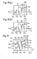
- FIGS. 7(a) and 7(b) respectively show a hybrid optical wavelength division multiplexer for bidirectional transmission of four waves and a hybrid optical wavelength division demultiplexer for bidirectional transmission of four waves.
- the hybrid optical wavelength division multiplexer for bidirectional transmission of four waves as shown in FIG. 7(a) is a modification of the arrangement of FIG. 4(a) so as to be able to transmit four waves, and employs four interference filters, as shown in FIG. 6, for multiplexing four optical signals of different wavelengths.
- FIG. 7(a) is a modification of the arrangement of FIG. 4(a) so as to be able to transmit four waves, and employs four interference filters, as shown in FIG. 6, for multiplexing four optical signals of different wavelengths.
- optical signals having wavelengths ⁇ 1 , ⁇ 3 , ⁇ 2 , ⁇ 4 , emitted from light-emitting diodes 36c, 36d, 36e, 36f in response to electric signals applied respectively to electric signal receiving terminals 38c, 38d, 38e, 38f are multiplexed and coupled to a common-port optical fiber 30.
- the hybrid optical wavelength division demultiplexer for bidirectional transmission of four waves as shown in FIG. 7(b) is modification of the arrangement of FIG. 4(b) so as to be able to receive four waves, and employs four interference filters, as shown in FIG. 5, for demultiplexing four optical signals of different wavelengths transmitted from the common-port optical fiber 30.
- optical signals having wavelengths ⁇ 1 , ⁇ 2 , ⁇ 3 , ⁇ 4 , transmitted from the common-port optical fiber 30 are detected by photodiodes 42e, 42c, 42f, 42d which issue electric signals through electric signal receiving terminals 44e, 44c, 44f, 44d, respectively.
- FIGS. 2, 4, 5 and 7 it is necessary to provide an increased distance between the light-emitting diodes and the common-port optical fibers.
- light emitted from the light-emitting diode is converted by the spherical lens into parallel beams of light which are directed toward the spherical lens in front of the common-port optical fiber.
- FIG. 8 shows coupling efficiency vs. distance characteristics obtained by employing a laser diode in the foregoing embodiments.
- the graph of FIG. 8 has a horizontal axis.
- the common-port optical fiber used is a standard optical fiber having a fiber core of a diameter of 50 pm, an outside diameter of 125 fID (50/125 GI), and an N.A. (numerical aperture) of 0.20.
- FIG. 9 shows coupling efficiency vs. distance characteristics obtained by employing light emitted from an LED.
- the data of FIG. 9 was measured using the same optical fiber as described in the above experiment, and the graph of FIG. 9 has horizontal and vertical axis indicative of the same quantities as those in FIG. 8.
- Fig. 9 indicates, as with FIG. 8, that the coupling efficiency will not be lowered if the coupling distance is increased.
Applications Claiming Priority (2)
| Application Number | Priority Date | Filing Date | Title |
|---|---|---|---|
| JP59038752A JPS60184216A (ja) | 1984-03-02 | 1984-03-02 | 混成型光合分波器 |
| JP38752/84 | 1984-03-02 |
Publications (2)
| Publication Number | Publication Date |
|---|---|
| EP0153722A2 true EP0153722A2 (de) | 1985-09-04 |
| EP0153722A3 EP0153722A3 (de) | 1986-06-11 |
Family
ID=12534026
Family Applications (1)
| Application Number | Title | Priority Date | Filing Date |
|---|---|---|---|
| EP85102054A Withdrawn EP0153722A3 (de) | 1984-03-02 | 1985-02-25 | Hybridischer optischer Wellenlängen-Multiplexer-Demultiplexer |
Country Status (2)
| Country | Link |
|---|---|
| EP (1) | EP0153722A3 (de) |
| JP (1) | JPS60184216A (de) |
Cited By (11)
| Publication number | Priority date | Publication date | Assignee | Title |
|---|---|---|---|---|
| EP0216174A1 (de) * | 1985-09-25 | 1987-04-01 | Siemens Aktiengesellschaft | Lichtweichen-Einheit |
| GB2191645A (en) * | 1986-06-13 | 1987-12-16 | Stc Plc | Optical telecommunication system |
| GB2223138A (en) * | 1987-04-13 | 1990-03-28 | Kollmorgen Corp | Optical multiplexing system |
| WO1990007135A1 (en) * | 1988-12-22 | 1990-06-28 | Italtel Società Italiana Telecomunicazioni S.P.A. | Transceiver hybrid module for the bidirectional transmission on a monomodal fibre optic of two optical signals |
| EP0268523B1 (de) * | 1986-11-04 | 1993-02-17 | Oki Electric Industry Company, Limited | Optische Einkopplungsvorrichtung für optischen Direktverstärker |
| EP0633483A1 (de) * | 1993-06-30 | 1995-01-11 | Nec Corporation | Optischer Wellenleiter-Multiplexer |
| US5812291A (en) * | 1995-03-22 | 1998-09-22 | Cselt Centro Studi E Laboratori Telecomunicazioni S.P.A. | Optical add-drop multiplexer for optical communication networks |
| US6571033B2 (en) | 2001-09-28 | 2003-05-27 | Corning Incorporated | Optical signal device |
| CN104597569A (zh) * | 2015-01-14 | 2015-05-06 | 青岛海信宽带多媒体技术有限公司 | 波分复用/解复用器以及光发射组件 |
| CN105739025A (zh) * | 2016-03-18 | 2016-07-06 | 苏州伽蓝致远电子科技股份有限公司 | 一种一端出光的立体式紧凑型多通道光波分复用器 |
| CN105739022A (zh) * | 2016-03-18 | 2016-07-06 | 苏州伽蓝致远电子科技股份有限公司 | 一种高生产效率的紧凑型多通道光波分复用器 |
Families Citing this family (2)
| Publication number | Priority date | Publication date | Assignee | Title |
|---|---|---|---|---|
| JP2009198756A (ja) * | 2008-02-21 | 2009-09-03 | Oki Semiconductor Co Ltd | 光送受信モジュール及びこれに用いる波長分岐フィルタ |
| JP6631361B2 (ja) * | 2016-03-29 | 2020-01-15 | 三菱電機株式会社 | 波長多重光通信モジュール |
Citations (2)
| Publication number | Priority date | Publication date | Assignee | Title |
|---|---|---|---|---|
| FR2258751A1 (de) * | 1974-01-18 | 1975-08-18 | Thomson Csf | |
| GB2014752A (en) * | 1978-01-31 | 1979-08-30 | Nippon Telegraph & Telephone | Element for use in optical multiplexer or de-multiplexer |
Family Cites Families (1)
| Publication number | Priority date | Publication date | Assignee | Title |
|---|---|---|---|---|
| JPS57190919A (en) * | 1981-05-20 | 1982-11-24 | Toshiba Corp | Optical multiplexer and demultiplexer |
-
1984
- 1984-03-02 JP JP59038752A patent/JPS60184216A/ja active Pending
-
1985
- 1985-02-25 EP EP85102054A patent/EP0153722A3/de not_active Withdrawn
Patent Citations (2)
| Publication number | Priority date | Publication date | Assignee | Title |
|---|---|---|---|---|
| FR2258751A1 (de) * | 1974-01-18 | 1975-08-18 | Thomson Csf | |
| GB2014752A (en) * | 1978-01-31 | 1979-08-30 | Nippon Telegraph & Telephone | Element for use in optical multiplexer or de-multiplexer |
Non-Patent Citations (2)
| Title |
|---|
| NATIONAL TELECOMMUNICATIONS CONFERENCE, vol. 2/4, November 30 - December 4, 1980, Houston-Texas, US, pages 34.7.1 - 34.7.4; T. AMEMIYA et al.: "Optical loop network controller module for camac system" * |
| OPTICAL COMMUNICATION CONFERENCE, September 17-19, 1979, Amsterdam, NL, pages 13.2-1 - 13.2-4; S. TAKEUCHI et al.: "Optical directional filter and its application to the bidirectional transmission system" * |
Cited By (13)
| Publication number | Priority date | Publication date | Assignee | Title |
|---|---|---|---|---|
| EP0216174A1 (de) * | 1985-09-25 | 1987-04-01 | Siemens Aktiengesellschaft | Lichtweichen-Einheit |
| GB2191645A (en) * | 1986-06-13 | 1987-12-16 | Stc Plc | Optical telecommunication system |
| GB2191645B (en) * | 1986-06-13 | 1990-09-05 | Stc Plc | Optical telecommunication systems |
| EP0268523B1 (de) * | 1986-11-04 | 1993-02-17 | Oki Electric Industry Company, Limited | Optische Einkopplungsvorrichtung für optischen Direktverstärker |
| GB2223138A (en) * | 1987-04-13 | 1990-03-28 | Kollmorgen Corp | Optical multiplexing system |
| WO1990007135A1 (en) * | 1988-12-22 | 1990-06-28 | Italtel Società Italiana Telecomunicazioni S.P.A. | Transceiver hybrid module for the bidirectional transmission on a monomodal fibre optic of two optical signals |
| EP0633483A1 (de) * | 1993-06-30 | 1995-01-11 | Nec Corporation | Optischer Wellenleiter-Multiplexer |
| US5457558A (en) * | 1993-06-30 | 1995-10-10 | Nec Corporation | Optical waveguide multiplexer for optical fiber amplifiers |
| US5812291A (en) * | 1995-03-22 | 1998-09-22 | Cselt Centro Studi E Laboratori Telecomunicazioni S.P.A. | Optical add-drop multiplexer for optical communication networks |
| US6571033B2 (en) | 2001-09-28 | 2003-05-27 | Corning Incorporated | Optical signal device |
| CN104597569A (zh) * | 2015-01-14 | 2015-05-06 | 青岛海信宽带多媒体技术有限公司 | 波分复用/解复用器以及光发射组件 |
| CN105739025A (zh) * | 2016-03-18 | 2016-07-06 | 苏州伽蓝致远电子科技股份有限公司 | 一种一端出光的立体式紧凑型多通道光波分复用器 |
| CN105739022A (zh) * | 2016-03-18 | 2016-07-06 | 苏州伽蓝致远电子科技股份有限公司 | 一种高生产效率的紧凑型多通道光波分复用器 |
Also Published As
| Publication number | Publication date |
|---|---|
| EP0153722A3 (de) | 1986-06-11 |
| JPS60184216A (ja) | 1985-09-19 |
Similar Documents
| Publication | Publication Date | Title |
|---|---|---|
| US5005935A (en) | Wavelength-division multiplexing optical transmission system | |
| US4362359A (en) | Coupling device for coupling signals into and out of a transmission glass-fiber | |
| US4708425A (en) | Bidirectional optical wavelength multiplexer-demultiplexer | |
| US4834485A (en) | Integrated fiber optics transmitter/receiver device | |
| US4904043A (en) | Optical data link dual wavelength coupler | |
| EP0153722A2 (de) | Hybridischer optischer Wellenlängen-Multiplexer-Demultiplexer | |
| US7309169B2 (en) | Single-channel communication device for optical fibre | |
| CN109254365A (zh) | 光接收模组及其制作方法、光接收器件 | |
| CN114257307B (zh) | 一种光纤到户混传光收发模块 | |
| CN115561737A (zh) | 基于多芯光纤接收信号光的激光雷达 | |
| US6694102B2 (en) | Optical configuration, in particular for bidirectional WDM systems, and a transceiving module for bidirectional optical data transmission | |
| US6591042B2 (en) | Fiber based wavelength de-multiplexing system | |
| CN101984565A (zh) | 多通道双功能波分复用光电集成模块 | |
| CN201708807U (zh) | 多通道双功能波分复用光电集成模块 | |
| CN209102958U (zh) | 光接收模组及光接收器件 | |
| CN100342676C (zh) | 带光功率探测的光波分复用/解复用器 | |
| US4773722A (en) | Two-way coupler for optical fibers | |
| CN216052307U (zh) | 一种光接收装置 | |
| JPS6289008A (ja) | 光通信用モジユ−ル | |
| CN210605101U (zh) | 一种基于光波导的多路波分解复用光接收组件 | |
| CN117192703B (zh) | 光芯片、激光雷达及可移动设备 | |
| CN116015471B (zh) | 光器件、光通信设备、光通信系统 | |
| KR100301937B1 (ko) | 공간압축통신채널증가를위한광멀티플렉서/광디멀티플렉서 | |
| KR100480304B1 (ko) | 양방향 광송수신기 및 이를 이용한 양방향 광송수신기 모듈 | |
| EP1102425A2 (de) | Optische Sender/empfängervorrichtung |
Legal Events
| Date | Code | Title | Description |
|---|---|---|---|
| PUAI | Public reference made under article 153(3) epc to a published international application that has entered the european phase |
Free format text: ORIGINAL CODE: 0009012 |
|
| AK | Designated contracting states |
Designated state(s): DE FR GB |
|
| PUAL | Search report despatched |
Free format text: ORIGINAL CODE: 0009013 |
|
| AK | Designated contracting states |
Kind code of ref document: A3 Designated state(s): DE FR GB |
|
| STAA | Information on the status of an ep patent application or granted ep patent |
Free format text: STATUS: THE APPLICATION IS DEEMED TO BE WITHDRAWN |
|
| 18D | Application deemed to be withdrawn |
Effective date: 19861212 |
|
| RIN1 | Information on inventor provided before grant (corrected) |
Inventor name: MAEDA, HIDENARIOKI ELECTRIC INDUSTRY CO., LTD. Inventor name: TAMURA, YASUAKIOKI ELECTRIC INDUSTRY CO., LTD. |