EP0153094A1 - Procédés et appareils pour fabriquer des produits alimentaires extrudés fourrés - Google Patents
Procédés et appareils pour fabriquer des produits alimentaires extrudés fourrés Download PDFInfo
- Publication number
- EP0153094A1 EP0153094A1 EP85300813A EP85300813A EP0153094A1 EP 0153094 A1 EP0153094 A1 EP 0153094A1 EP 85300813 A EP85300813 A EP 85300813A EP 85300813 A EP85300813 A EP 85300813A EP 0153094 A1 EP0153094 A1 EP 0153094A1
- Authority
- EP
- European Patent Office
- Prior art keywords
- extrudate
- casing
- slit
- extruded
- filling
- Prior art date
- Legal status (The legal status is an assumption and is not a legal conclusion. Google has not performed a legal analysis and makes no representation as to the accuracy of the status listed.)
- Granted
Links
- 235000013305 food Nutrition 0.000 title claims abstract description 7
- 238000000034 method Methods 0.000 title claims description 26
- 239000000463 material Substances 0.000 claims abstract description 60
- 238000004519 manufacturing process Methods 0.000 claims description 9
- 238000011144 upstream manufacturing Methods 0.000 claims description 9
- 235000012438 extruded product Nutrition 0.000 claims description 4
- 238000010411 cooking Methods 0.000 abstract description 5
- 238000001125 extrusion Methods 0.000 description 18
- 239000000047 product Substances 0.000 description 13
- 239000006071 cream Substances 0.000 description 6
- 239000007789 gas Substances 0.000 description 3
- 239000004615 ingredient Substances 0.000 description 3
- 235000013372 meat Nutrition 0.000 description 3
- 239000007787 solid Substances 0.000 description 3
- MIDXCONKKJTLDX-UHFFFAOYSA-N 3,5-dimethylcyclopentane-1,2-dione Chemical compound CC1CC(C)C(=O)C1=O MIDXCONKKJTLDX-UHFFFAOYSA-N 0.000 description 2
- 230000015572 biosynthetic process Effects 0.000 description 2
- 235000013736 caramel Nutrition 0.000 description 2
- 235000009508 confectionery Nutrition 0.000 description 2
- 239000000203 mixture Substances 0.000 description 2
- 230000001105 regulatory effect Effects 0.000 description 2
- 235000011888 snacks Nutrition 0.000 description 2
- 206010013710 Drug interaction Diseases 0.000 description 1
- 229920000881 Modified starch Polymers 0.000 description 1
- 241000209140 Triticum Species 0.000 description 1
- 235000021307 Triticum Nutrition 0.000 description 1
- 230000002411 adverse Effects 0.000 description 1
- 238000013459 approach Methods 0.000 description 1
- 235000013351 cheese Nutrition 0.000 description 1
- 239000003795 chemical substances by application Substances 0.000 description 1
- 239000003086 colorant Substances 0.000 description 1
- 238000001816 cooling Methods 0.000 description 1
- 230000007547 defect Effects 0.000 description 1
- 230000000694 effects Effects 0.000 description 1
- 238000002474 experimental method Methods 0.000 description 1
- 239000000945 filler Substances 0.000 description 1
- 239000012467 final product Substances 0.000 description 1
- 235000013312 flour Nutrition 0.000 description 1
- 238000009472 formulation Methods 0.000 description 1
- 230000003993 interaction Effects 0.000 description 1
- 238000002156 mixing Methods 0.000 description 1
- 239000013641 positive control Substances 0.000 description 1
- 230000002028 premature Effects 0.000 description 1
- 102000004169 proteins and genes Human genes 0.000 description 1
- 108090000623 proteins and genes Proteins 0.000 description 1
- 238000007493 shaping process Methods 0.000 description 1
- 239000000126 substance Substances 0.000 description 1
- XLYOFNOQVPJJNP-UHFFFAOYSA-N water Substances O XLYOFNOQVPJJNP-UHFFFAOYSA-N 0.000 description 1
Images
Classifications
-
- A—HUMAN NECESSITIES
- A21—BAKING; EDIBLE DOUGHS
- A21C—MACHINES OR EQUIPMENT FOR MAKING OR PROCESSING DOUGHS; HANDLING BAKED ARTICLES MADE FROM DOUGH
- A21C9/00—Other apparatus for handling dough or dough pieces
- A21C9/06—Apparatus for filling pieces of dough such as doughnuts
- A21C9/061—Making continuous filled tubular products, e.g. with subsequent cutting
-
- A—HUMAN NECESSITIES
- A23—FOODS OR FOODSTUFFS; TREATMENT THEREOF, NOT COVERED BY OTHER CLASSES
- A23P—SHAPING OR WORKING OF FOODSTUFFS, NOT FULLY COVERED BY A SINGLE OTHER SUBCLASS
- A23P30/00—Shaping or working of foodstuffs characterised by the process or apparatus
- A23P30/20—Extruding
- A23P30/25—Co-extrusion of different foodstuffs
Definitions
- This invention relates tp methods and apparatus for making filled extruded products and is concerned particularly with such methods and apparatus in which the extrusion cooking of food product components is involved.
- Filled snack products can be made by a process of co-extrusion, in which a casing material is extruded through an annular die, simultaneously with a filling material which is extruded through a central mandrel.
- cooking or other treatment of one or both of the materials often takes place, as the materials pass through the co-extrusion nozzles used, so that at least one of the materials may expand or otherwise undergo change as it is discharged.
- co-extrusion methods and apparatus can give rise to difficulties in practice, however.
- US-A-3751202 refers to problems which arise due to the characteristics of the different materials, citing the scorching or burning of a meat filling, due to the high temperature needed for satisfactory production of a protein casing, or adverse effects caused by premature cooling of the casing itself, as heat is lost to the meat filling.
- Another main cause of difficulty with co-extrusion techniques is the steam and/or other gases or vapours which can be evolved from either or both of the materials as they undergo co-extrusion, especially if the steam or other gaseous material is given off by the filling material inside the casing.
- Attempts to alleviate such problems include the application of suction at the annular region where the casing meets the filling material. Such an arrangement is disclosed in published European Application No. 0071183, for instance.
- a further cause of difficulty in co-extrusion is that the casing material must necessarily pass to either side of the conduit which directs the filling material to the mandrel and irregularities can easily occur in the extruded casing, because the material does not rejoin satisfactorily downstream of the supply conduit, sometimes resulting in incomplete formation of the casing.
- co-extrusion is an obvious principle to adopt in the manufacture of products which consist of a tubular casing containing a core-like filling, this principle can give rise to notable technical difficulties and the present invention avoids these by dispensing with co-extrusion. As a result, much closer control can be achieved by simpler means.
- Extrusion is employed in carrying out the invention, because it is an especially convenient way of preparing tubular casings, but the invention allows simpler control of the materials being used. Also, as the supply of each material is largely independent of the other, a failure or defect in the supply of one material can be readily followed by a stoppage of the other, so that excessive wastage of materials is easily avoided.
- a method and an apparatus for making filled extruded products wherein a casing material is extruded in the form of a unitary tubular component having a cross-section of closed-loop shape, the extruded casing has a longitudinal opening made in it by being advanced relative to a cutter member and the casing is then filled by being advanced past at least one supply duct for filling material located downstream of the cutter member, so as to pass through the longitudinal opening into the extrudate, whereby the or each filling material is introduced into the extrudate, a force system which tends to close the longitudinal opening being arranged to act upon the extruded casing downstream of the location of the or each supply duct.
- the force system can be arranged to close the longitudinal opening in the extrudate or, instead, it can be arranged to reduce, or even merely prevent any increase in, the width of the longitudinal openings.
- the force system acts directly upon the unitary extrudate and, moreover, in most practical forms of the method and the apparatus, the force system operates in a region located downstream of the discharge outlet from the or each supply duct for the filling material. Usually, such a region is also downstream of the position of entry of the or each supply duct into the longitudinal opening formed in the extrudate by the cutter.
- the region of operation of the force system is upstream of the discharge outlet from the supply duct, which is therefore arranged to pass through the opening and, within the extruded casing, to extend through the region of operation of the force system, so as to discharge on its downstream side.
- the tubular casing component is formed as a unitary extrudate before it is opened up by the cutter member, it can be arranged to complete any expansion or other change in configuration between leaving the extrusion nozzle and reaching the cutter member.
- its shape is stabilized before it is slit open and therefore before the or each filling material is fed into it, so that it has a tendency to retain or resume this stabilised shape and therefore the edges on either side of the opening remain in contact.
- the (or each) supply duct can, if required, be arranged to extend in the downstream direction within the extrudate so that its outlet end is located beyond the region of application of the force system which causes or allows the longitudinal opening to close; in this way, the tubular casing has already attained its final stabilised form before the discharge of the filling material into it, so that the desired degree of filling can be achieved irrespective of the cross-section of the tubular casing upstream of the region of action of the force system.
- the or each supply duct extends through the longitudinal opening formed in the tubular casing component and the filling material is supplied as required so as to fill the core of the tubular casing.
- two filling materials e.g. of different colours
- One supply duct located nearer the cutter member can supply a lower filling material and its outlet end is preferably located near the bottom of the space inside the casing, the rate of supply being regulated so that the first filling material fills the lower part of the casing.
- the outlet end of the second duct which is preferably located somewhat further downstream in the longitudinal opening, is preferably located in the upper part of the hollow inside of the casing, so that the second filling material is discharged on to the first and the casing is thus fully filled.
- the extrudate has a cross-section of closed-loop form, which is identical or closely similar to the cross-section of the casing in the resultant filled product; a single opening only is made in the casing and, for this purpose, a knife or other cutter member is disposed on the upstream side of the supply duct (or ducts) for the filling material and this cutter member forms an opening, which can be either a slit or a slot, in the extrudate to allow the filling material to be introduced; the cutter member is preferably arranged to form a slit. i.e.
- the cutter member can be a knife blade or other sharp edge, which is stationary or which operates about a stationary axis, e.g. by reciprocating along an axis fixed in relation to its intersection with the casing.
- the cutter also is preferably inclined to the direction of advance of the extrudate, an especially preferred arrangement being one in which the fixed or reciprocated blade is inclined to the extrudate so that the wall of the casing is opened fran the outside to the inside.
- the cutter member can also be a rotary knife, as opposed to a straight blade, and can be driven so as to rotate about a stationary axis. Again, it is preferable for the knife to open the casing from the outside to the inside.
- the force system can include a component in the direction of advance of the product.
- rollers acting upon the casing can be driven so as to exert a pulling or stretching action on the product, which is advantageous in consolidating it and generally affecting its final shape and form.
- a system of driven belts can be used in place of rollers to give a more positive control of the force system for forming the final shape.
- the direction in which extrusion is effected can be selected as desired in order to carry out manufacture as conveniently as possible.
- the supply duct (or the first, if more than one is used) is spaced downstream from the cutter member by a substantial distance, relative to the other dimensions in use, i.e. so that any water vapour or other gaseous or volatile substance or agent evolved from the extruded and cooked casing can escape via the longitudinal opening, before the filling step per se begins.
- the longitudinal opening is preferably formed in the uppermost part of the tubular extrudate. It has been found that the problems which can arise with co-extrusion cooking can be completely avoided by use of the present invention.
- reference 10 designates an arrow indicating the direction of advance of the extrudate, from which the tubular casing of the filled product is made
- reference 11 is an arrow indicating the introduction of filling material which might consist of a cream, confectionery or other sweet filling or alternatively a savoury filling based on for example cheese or meat.
- the invention also permits the possibility of using more than one filling material thus producing products with multiple fillings.
- the filling material is fed to a supply duct 16 which conveys it for discharge within an extrudate 14
- reference 12 is an arrow indicating the direction of application of a force, one or more of such forces 12 forming a force system which tends to close the opening in the filled extrudate 14/19, i.e. by wholly or partly closing it or preventing it from widening further, in a position downstream of the location of the supply duct within such opening.
- the extrudate 14 advancing in the direction 10 typically comprises a mixture comprising expanded pregelatinized starch, for instance.
- a filling material 19 is introduced into an extrudate 14, which is made in a form having a closed-loop cross-section, by way of an opening which is formed before, i.e. upstream of, or as the extrudate 14 advances past the supply duct 16.
- the extrudate 14 is formed with a cross-section which is a square or rectangle, although a closed-loop cross-section of any other shape can of course be used.
- a cutter member 15, such as a stationazyvertical knife, is located so as to extend down into the interior of the extrudate 14 from the outside and it separates the upper web of the extrudate 14, as the latter approaches the supply duct 16, which can thus have its outlet end 17 located within the open core of the extrudate 14, so that the filling material 19 can be discharged through the resultant longitudinal opening 20 into the extrudate 14.
- the cutter member 15 can be positioned close to the supply duct 16, for instance by being mounted upon it, or it can be mounted upon the same support arrangements (not shown) as the supply duct 16. Lateral pressure is preferably applied to the filled extrudate 14 downstream of the supply duct 16, for instance by a pair of vertical rollers 18, which produce the force system 12 required.
- the cutter member 15 need not be closely adjacent the supply duct 16 and can be and preferably is mounted further upstream of it, for instance as shown in dotted lines at 21. Generally, it is preferable to arrange the cutter member 15 so that it is a substantial distance upstream of the supply duct 16. For instance, if the extrudate 14 is rectangular and the conditions under which it is made cause it to assume dimensions in the range from 5-30 mm in width and from 5-30 mm in height, e.g. 19 x 16 mm, the cutter member 15 can be positioned from 5-50 cm, e.g. 30 cm, upstream of the supply duct 16.
- the extrudate 14 stabilizes in shape as it advances from the cutter 15 to the filling material supply duct 16 and air, steam or other gaseous or vaporous materials can be largely or wholly eliminated from the outside and also from the inside of the casing, the latter by way of a slit or slot 20 produced by the cutter 15 as a longitudinal opening in the product casing constituted by the extrudate 14.
- the slit 20 or other form of the opening may remain closed except where it is held open by the cutter 15 and/or the duct 16, so that the forces 12 comprise the inherent tendency of the extrudate 14 to retain its stabilised cross-section, or the slit 20 or other opening may remain open until the extrudate 14 advances to the region of application of the forces 12, e.g.
- the rollers 18 or other means for applying the force system 12 to urge or allow the opening in the extrudate 14 to close are preferably arranged so that the slot 20 is closed up at least by the time the filled extrudate 14 passes the region where this force system 12 is applied.
- the slot 20 can be arranged to close, depending upon the nature of the material and its ability to return to its original position, immediately downstream of the supply duct 16. Gases or vapours, e.g. steam, evolved from either the extrudate 14 or the filling material 19, as the process of manufacture proceeds, escape in a highly satisfactory way, through the slot 20 or other opening. Where products are being made where such evolution of gas or vapour occurs, it may be preferable to arrange closure of the opening 20, to the extent desired, downstream of the outlet 17 from the supply duct 16 and therefore of the region where this evolution mainly occurs.
- the rollers 18,18 can be driven or they can be replaced by a system of driven belts, so as to assist the advance of the product and, in particular, so as to increase the speed of this advance.
- This feature can be employed so as to subject the product to a pulling or stretching action and can thus participate in determining the shape of the final product.
- the method of the invention works very satisfactorily and allows a considerable degree of precise control over the rates of advance of the extrudate 14 and the filling material 19 supplied to it. Also, the rate of supply of the filling material 19 can be regulated accurately so as to ensure the desired degree of filling, depending upon the nature, temperature, possible expansion and other properties of the materials and any inter-action which there may be between them.
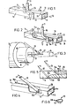
- FIG.2 this shows the manufacture of a filled extrudate by a method and on an apparatus generally similar to the method and apparatus of Fig.1 and like parts carry the same references.
- a preferred arrangement of the cutter member is shown in the form of a knife 15a which, unlike the knife 15 of Fig.1, is inclined so as to cut into the wall of the extrudate 14 from its outside to its inside, as the latter advances past the cutter 15a. It has been found that this ensures a smooth incision in the casing.
- the cutter blade 15 it is especially preferable, in practice, for the cutter blade 15 to reciprocate in the direction of its cutting edge, so as to open the casing 14 by a sawing action, as this ensures that the cutter blade remains fully effective in producing a smooth and even opening 20 in the casing 14. Also, it can be seen that the cutter 15a is located a substantial distance in advance of the filling supply duct 16, in the direction of movement of the extrudate 14, which ensures that a slit or slot 20a of appreciable length is formed, as the casing is opened by the cutter 15a and then moves to the duct 16.
- This long slit or slot 20a is highly effective in allowing steam or other gaseous products evolved from the extrusion-cooked casing 14 to escape from the extrudate 14 and especially from its inside, before it reaches the outlet 17 from the supply duct 16 and so receives the filling material.
- Fig. 2 also shows that the supply duct 16 can be arranged to terminate in an advanced position in the extrudate 14 relative to application of the force system 12, i.e. downstream of the point of application of these forces. Also, this extends the length between opening of the extrudate by the knife 15a and introduction of the filling material 19 as it is discharged at the outlet 17 from the duct 16, which can have an extension 17a for this purpose, which in use is wholly located within the hollow interior of the extrudate 14.
- Fig. 3 shows the discharge end of a cooker/extruder die 24, having a shaping collar 25 with a discharge aperture 26 with any desired cross-section e.g. oblong, circular or, as shown, square, from which the unitary casing or extrudate 14 is discharged.
- a solid mandrel 27 is preferably arranged, which serves to support the blade 28 of a cutter in the form of a laboratory scalpel 29 which is supported, e.g. from the collar 25, so as to be inclined relative to the horizontal axis through the die 24, the collar 25 and the mandrel 27.
- the steps of extrusion cooking and opening of the casing, carried out as shown in Fig. 3, are followed by the filling step, shown in Figs. 4 to 6.
- the extrudate 14 again shown as a hollow unitary square or rectangle in cross-section and having an upper web 14a and a lower web 14b, has the slit 20 formed by the cutter 28 in its top web 14a.
- the adjacent edges may return to be in contact after passing the cutter blade 28, as shown at 20, or they may remain spaced apart, so as to form a slot, as shown at 20a, until the filling material supply duct shown at 30 in Fig. 4 is reached.
- the duct 30 preferably has a cross-section at its lower or outlet end 30a as shown in Fig.
- the outlet end 30a is preferably made with a relatively flattened cross-section which defines a point 30b where the slit halves of the top web 14a pass to either side in operation.
- the duct 30 is, in practice, preferably located a substantial distance downstream from the blade 28 of Fig.3, e.g. a distance in the range from 20 to 50 cm, for instance 30 cm.
- the blade 28 can take the form of a circular knife, which if desired can be made to rotate.
- Fig. 5 shows a variant, in cross-section, in which the duct 30 receives a first filling material, as shown at 11, and discharges it from its lower or outlet end 30a so that it forms a layer 19a contained in the lower half of the casing 14.
- the outlet end 30a is desirably located close to the floor or lower web 14b of the extrudate 14.
- a second supply duct 31 also preferably having the cross-section shown in Fig.6 at its lower end 31a is provided.
- the second duct 31 is desirably located downstream from the first duct 30 by a distance which is of the same order as that separating the first duct 30 from the cutter blade 28, e.g. in the range from 20 to 40 cm, for instance 30 cm.
- the second duct 31 discharges a second filling material 19b from its outlet end 31a and so fills the remaining space within the extrudate 14.
- the outlet end 31a of the second supply duct 31 should be located above the upper surface of the first filling 19a and is therefore preferably positioned adjacent the upper web 14a of the casing or extrudate 14.
- the amounds indicated are by weight. However, various other ingredients can be used, in conjunction with or instead of some of the ingredients mentioned.
- the extrudate is usually processed so that it leaves the die at approximately 180°C. Referring to Fig. 3, the die 24 used for this work had a 6 mm: 4 mm annulus, with the solid mandrel 27.
- the material expanded to a given shape which was controlled by the collar 25, e.g. a 19 x 16 mm oblong shape.
- the extrudate 14 left the collar 25 it was slit in the upper surface or web 14a (Fig. 4) with the laboratory scalpel 28 held in place on the mandrel 27. Approximately one foot (30 cm) downstream, all the steam had come away from the extrudate 14 and the filling pipe or duct 30, inserted through the slit 20 (20a), was used to pump a filling material at 40° - 50°C into the tube centre.
- a typical cream filling formation is as follows, again in amounts by weight: Also, a commercial caramel was successfully filled into the extrudate 14, using this technique.
- a double cream filling ( F ig.5) was made by placing the second filler pipe or duct 31 one foot (30 cm) downstream from the first, 30. The outlets from each duct inside the extrudate 14 was adjusted to prevent mixing of the two coloured creams.
Landscapes
- Engineering & Computer Science (AREA)
- Life Sciences & Earth Sciences (AREA)
- Food Science & Technology (AREA)
- Manufacturing & Machinery (AREA)
- Chemical & Material Sciences (AREA)
- Polymers & Plastics (AREA)
- Formation And Processing Of Food Products (AREA)
- Confectionery (AREA)
- Manufacturing And Processing Devices For Dough (AREA)
- Extrusion Moulding Of Plastics Or The Like (AREA)
Priority Applications (1)
| Application Number | Priority Date | Filing Date | Title |
|---|---|---|---|
| AT85300813T ATE31466T1 (de) | 1984-02-15 | 1985-02-07 | Verfahren und vorrichtungen zur herstellung von gefuellten extrudierten nahrungsmitteln. |
Applications Claiming Priority (2)
| Application Number | Priority Date | Filing Date | Title |
|---|---|---|---|
| GB8403966 | 1984-02-15 | ||
| GB848403966A GB8403966D0 (en) | 1984-02-15 | 1984-02-15 | Filled products involving extrusion |
Publications (2)
| Publication Number | Publication Date |
|---|---|
| EP0153094A1 true EP0153094A1 (fr) | 1985-08-28 |
| EP0153094B1 EP0153094B1 (fr) | 1987-12-23 |
Family
ID=10556639
Family Applications (1)
| Application Number | Title | Priority Date | Filing Date |
|---|---|---|---|
| EP85300813A Expired EP0153094B1 (fr) | 1984-02-15 | 1985-02-07 | Procédés et appareils pour fabriquer des produits alimentaires extrudés fourrés |
Country Status (5)
| Country | Link |
|---|---|
| US (1) | US4618499A (fr) |
| EP (1) | EP0153094B1 (fr) |
| AT (1) | ATE31466T1 (fr) |
| DE (1) | DE3561221D1 (fr) |
| GB (1) | GB8403966D0 (fr) |
Cited By (5)
| Publication number | Priority date | Publication date | Assignee | Title |
|---|---|---|---|---|
| EP0236134A1 (fr) * | 1986-03-05 | 1987-09-09 | Nabisco Brands, Inc. | Ajustage d'extrusion |
| US4888192A (en) * | 1986-03-05 | 1989-12-19 | Nabisco Brands, Inc. | Method for extrusion of baked goods |
| WO1990014767A1 (fr) * | 1989-06-07 | 1990-12-13 | Nabisco Brands, Inc. | Produit alimentaire fourre gonflant a la cuisson au four a micro-onde, procede et appareil pour sa fabrication |
| WO1997019604A1 (fr) * | 1995-11-30 | 1997-06-05 | Societe Des Produits Nestle S.A. | Produit alimentaire comprenant un article comestible, mobile librement dans un corps creux, et appareil de production de celui-ci |
| EP1738649A1 (fr) * | 2005-06-30 | 2007-01-03 | Albert Handtmann Maschinenfabrik GmbH & Co. KG | Procédé et dispositif pour produire un chapelet de saucisses ayant un section au choix |
Families Citing this family (40)
| Publication number | Priority date | Publication date | Assignee | Title |
|---|---|---|---|---|
| US4808422A (en) * | 1984-06-07 | 1989-02-28 | Frito-Lay, Inc. | Center-filled food products |
| US5296247A (en) * | 1988-05-26 | 1994-03-22 | Cpc International Inc. | Method of making pre-cooked filled pasta products by co-extrusion |
| US5216946A (en) * | 1988-05-26 | 1993-06-08 | Cpc International Inc. | Precooked filled pasta products made by co-extrusion |
| US5015488A (en) * | 1989-06-07 | 1991-05-14 | Nabisco Brands, Inc. | Cookie production with extrusion heat treatment and post extrusion mixing and baking |
| US5079012A (en) * | 1989-06-07 | 1992-01-07 | Nabisco Brands, Inc. | Shelf stable cookie product containing heat and shear sensitive additives and method of making |
| US4999208A (en) * | 1989-06-07 | 1991-03-12 | Nabisco Brands, Inc. | Extrusion baking of cookies having liposome encapsulated ingredients |
| US5015489A (en) * | 1989-06-07 | 1991-05-14 | Nabisco Brands, Inc. | Production of cookies with extrusion and post extrusion baking |
| US4957041A (en) * | 1989-06-07 | 1990-09-18 | Nabisco Brands, Inc. | Extruder apparatus for producing an at least partially baked product having a cookie-like crumb structure including a post-extrusion radio frequency device |
| US5071668A (en) * | 1989-06-07 | 1991-12-10 | Nabisco Brands, Inc. | Extrusion baking of cookies containing heat and shear sensitive additives |
| US5077074A (en) * | 1989-06-07 | 1991-12-31 | Nabisco Brands, Inc. | Preparation of cookie products involving extrusion heating and wire cutting |
| US4979434A (en) * | 1989-06-07 | 1990-12-25 | Nabisco Brands, Inc. | Extruder apparatus for producing an at least partially baked product having a cookie-like crumb structure |
| US4957042A (en) * | 1989-06-07 | 1990-09-18 | Nabisco Brands, Inc. | Extruder and continuous mixer arrangement for producing an at least partially baked product having a cookie-like crumb structure including a post-extrusion microwave device |
| US4949628A (en) * | 1989-06-07 | 1990-08-21 | Nabisco Brands, Inc. | Extruder and continuous mixer arrangement for producing an at least partially baked product having a cookie-like crumb structure, the extruder including a microwave applicator |
| US4960043A (en) * | 1989-06-07 | 1990-10-02 | Nabisco Brands, Inc. | Extruder and continuous mixer arrangement for producing an at least partially baked product having a cookie-like crumb structure |
| US4984514A (en) * | 1989-06-07 | 1991-01-15 | Nabisco Brands, Inc. | Extruder apparatus for producing an at least partially baked product having a cookie-like crumb structure including a post extrusion microwave device |
| US4938127A (en) * | 1989-06-07 | 1990-07-03 | Nabisco Brands, Inc. | Extruder and continuous mixer arrangement for producing an at least partially baked product having a cookie-like crumb structure including a post-extrusion radio frequency device |
| US5015490A (en) * | 1989-06-07 | 1991-05-14 | Nabisco Brands, Inc. | Production of extruded baked products without oil separation |
| US5030468A (en) * | 1989-06-07 | 1991-07-09 | Nabisco Brands, Inc. | Production of leavened products using high temperature mixing |
| DK0421509T3 (da) * | 1989-10-02 | 1995-06-26 | Unilever Plc | Næringsmiddelprodukt |
| US5160754A (en) * | 1990-03-15 | 1992-11-03 | Asahi Denka Kogyo Kabushiki Kaisha | Dough of pie, etc. having a slit roll configuration |
| US5524529A (en) * | 1995-09-20 | 1996-06-11 | 562186 Alberta Ltd. | Rotary stamper disk |
| US5687638A (en) * | 1995-09-20 | 1997-11-18 | 562186 Alberta Ltd. | Apparatus for producing filled food products |
| US6399128B1 (en) * | 1996-05-29 | 2002-06-04 | The Sandwich Factory, Co. | Injection of foodstuff to fill bagels and breads |
| DE19842546A1 (de) * | 1998-09-17 | 2000-03-23 | Werner Sinnig | Pommes frites Applikationsfüllungsvorrichtung |
| US6413572B1 (en) | 1999-08-24 | 2002-07-02 | Michael Foods, Inc. | Enhanced precooked egg product and process for formulation of precooked egg products |
| US6383535B1 (en) | 2000-03-16 | 2002-05-07 | Bestfoods | Extruded potato casing and method of making |
| US7288279B2 (en) | 2001-12-21 | 2007-10-30 | Michael Foods Of Delaware, Inc. | Formulated fried egg product |
| US20030118714A1 (en) | 2001-12-21 | 2003-06-26 | Michael Foods Of Delaware, Inc. | Formulation and process to prepare a premium formulated fried egg |
| US7241469B2 (en) | 2002-05-30 | 2007-07-10 | Michael Foods, Inc. | Formulation and process to prepare a pre-formed filing unit |
| WO2004049835A2 (fr) * | 2002-12-02 | 2004-06-17 | Brient Scott E | Procedes et appareils destines a la distribution de condiments |
| US20050214421A1 (en) * | 2004-03-24 | 2005-09-29 | Kraft Foods Holdings, Inc. | Method and apparatus for extruding filled doughs |
| FR2879898B1 (fr) * | 2004-12-24 | 2007-04-06 | Clextral | Produit alimentaire, son procede de fabrication et dispositif pour la mise en oeuvre d'une forme particuliere de ce procede |
| US20080038427A1 (en) * | 2006-08-09 | 2008-02-14 | The Quaker Oats Company | Method for adding slits to expose fruit filling in a co-extruded bar |
| US8334005B2 (en) * | 2008-11-14 | 2012-12-18 | Kraft Foods Global Brands Llc | Ribbon cutter apparatus and method for making sandwich baked goods |
| EP2757901A4 (fr) * | 2011-09-20 | 2014-08-27 | Nestec Sa | Jouet comestible à mâcher pour animal |
| US8877277B2 (en) | 2011-11-29 | 2014-11-04 | Frito-Lay North America, Inc. | Supercritical fluid extrusion method, apparatus and system for making a food product |
| US8986774B2 (en) | 2011-11-29 | 2015-03-24 | Frito-Lay North America, Inc. | Supercritical fluid extruded food product |
| USD809240S1 (en) | 2015-04-24 | 2018-02-06 | Mars, Incorporated | Confectionery bar |
| USD822329S1 (en) | 2014-10-31 | 2018-07-10 | Mars, Incorporated | Confectionery bar |
| US11388909B2 (en) * | 2018-10-02 | 2022-07-19 | Pure Nature Foods, LLC | Apparatus and method for post-extrusion filling and closure of an extrudate |
Citations (3)
| Publication number | Priority date | Publication date | Assignee | Title |
|---|---|---|---|---|
| US1542710A (en) * | 1924-04-23 | 1925-06-16 | William B Laskey | Frocess of making filled candy |
| FR944011A (fr) * | 1946-04-03 | 1949-03-24 | Procédé de fabrication de pâtes alimentaires en bandes planes continues, et dispositif pour sa mise en oeuvre et leur introduction dans les machines à façonner | |
| US2960045A (en) * | 1950-02-25 | 1960-11-15 | Pentzlin Kurt | Making molded pastry |
Family Cites Families (6)
| Publication number | Priority date | Publication date | Assignee | Title |
|---|---|---|---|---|
| US3551161A (en) * | 1969-01-02 | 1970-12-29 | Esther Whitestone | Method of preparing a proteinpotato article |
| US3751202A (en) * | 1971-04-15 | 1973-08-07 | Gen Mills Inc | Coextrusion apparatus |
| US4283430A (en) * | 1977-04-14 | 1981-08-11 | Carnation Company | Preparing centerfilled food product |
| US4275647A (en) * | 1977-04-14 | 1981-06-30 | Carnation Company | Apparatus for producing a centerfilled food product |
| US4309450A (en) * | 1980-09-19 | 1982-01-05 | Seibert Robert W | Method for manufacturing a seafood product |
| DE3129947C2 (de) * | 1981-07-29 | 1985-08-08 | Convent Knabber-Gebäck GmbH & Co KG, 5000 Köln | Düsenkopf für einen Kochextruder |
-
1984
- 1984-02-15 GB GB848403966A patent/GB8403966D0/en active Pending
-
1985
- 1985-02-07 AT AT85300813T patent/ATE31466T1/de not_active IP Right Cessation
- 1985-02-07 DE DE8585300813T patent/DE3561221D1/de not_active Expired
- 1985-02-07 EP EP85300813A patent/EP0153094B1/fr not_active Expired
- 1985-02-14 US US06/701,684 patent/US4618499A/en not_active Expired - Fee Related
Patent Citations (3)
| Publication number | Priority date | Publication date | Assignee | Title |
|---|---|---|---|---|
| US1542710A (en) * | 1924-04-23 | 1925-06-16 | William B Laskey | Frocess of making filled candy |
| FR944011A (fr) * | 1946-04-03 | 1949-03-24 | Procédé de fabrication de pâtes alimentaires en bandes planes continues, et dispositif pour sa mise en oeuvre et leur introduction dans les machines à façonner | |
| US2960045A (en) * | 1950-02-25 | 1960-11-15 | Pentzlin Kurt | Making molded pastry |
Cited By (5)
| Publication number | Priority date | Publication date | Assignee | Title |
|---|---|---|---|---|
| EP0236134A1 (fr) * | 1986-03-05 | 1987-09-09 | Nabisco Brands, Inc. | Ajustage d'extrusion |
| US4888192A (en) * | 1986-03-05 | 1989-12-19 | Nabisco Brands, Inc. | Method for extrusion of baked goods |
| WO1990014767A1 (fr) * | 1989-06-07 | 1990-12-13 | Nabisco Brands, Inc. | Produit alimentaire fourre gonflant a la cuisson au four a micro-onde, procede et appareil pour sa fabrication |
| WO1997019604A1 (fr) * | 1995-11-30 | 1997-06-05 | Societe Des Produits Nestle S.A. | Produit alimentaire comprenant un article comestible, mobile librement dans un corps creux, et appareil de production de celui-ci |
| EP1738649A1 (fr) * | 2005-06-30 | 2007-01-03 | Albert Handtmann Maschinenfabrik GmbH & Co. KG | Procédé et dispositif pour produire un chapelet de saucisses ayant un section au choix |
Also Published As
| Publication number | Publication date |
|---|---|
| DE3561221D1 (en) | 1988-02-04 |
| ATE31466T1 (de) | 1988-01-15 |
| US4618499A (en) | 1986-10-21 |
| GB8403966D0 (en) | 1984-03-21 |
| EP0153094B1 (fr) | 1987-12-23 |
Similar Documents
| Publication | Publication Date | Title |
|---|---|---|
| EP0153094B1 (fr) | Procédés et appareils pour fabriquer des produits alimentaires extrudés fourrés | |
| AU592411B2 (en) | Nozzle for extrusion | |
| KR0144722B1 (ko) | 반죽체의 분할/절단 장치 및 방법 | |
| US4567051A (en) | Method for producing snacks from dough | |
| US6458302B1 (en) | System and method for forming plastic articles | |
| JPS6236643B2 (fr) | ||
| CA2017787A1 (fr) | Appareil et methode pour le pompage, l'homogenisation et la separation de la pate et d'autres produits du genre | |
| US2960045A (en) | Making molded pastry | |
| AU2005201820A1 (en) | Process for preparing filled cracker products | |
| US4268532A (en) | Process for extruding and forming portion controlled frozen food products | |
| US4195489A (en) | Portion controlled frozen food | |
| AU779513B2 (en) | Method and apparatus for reforming dairy products | |
| MXPA04012294A (es) | Producto alimentario revestido, composicion, procedimiento y aparato para su fabricacion. | |
| US4258066A (en) | Process for extruding and forming portion controlled frozen food | |
| US2145240A (en) | Method of packaging plastic comestibles | |
| JP2005533511A6 (ja) | 被覆された食品、組成物、被覆方法及び該食品の製造装置 | |
| US20050123663A1 (en) | Shredded food products and methods of producing and applying shredded food products | |
| US4526795A (en) | Method for producing croissants | |
| MX2012005783A (es) | Aparato y metodo para aplicacion de especias secas. | |
| US4264635A (en) | Automatic pasta perforator and method of making pasta | |
| US20210392942A1 (en) | Method of Manufacturing a Meat Jerky Straw | |
| US2642819A (en) | Machine for making food products | |
| US3444826A (en) | Method and apparatus for making a baked edible tubular product | |
| US5212960A (en) | Method and a system for producing extruded edible ice products | |
| US4119252A (en) | Portion controlled frozen food |
Legal Events
| Date | Code | Title | Description |
|---|---|---|---|
| PUAI | Public reference made under article 153(3) epc to a published international application that has entered the european phase |
Free format text: ORIGINAL CODE: 0009012 |
|
| AK | Designated contracting states |
Designated state(s): AT BE CH DE FR GB IT LI LU NL SE |
|
| 17P | Request for examination filed |
Effective date: 19851024 |
|
| 17Q | First examination report despatched |
Effective date: 19861120 |
|
| ITF | It: translation for a ep patent filed | ||
| GRAA | (expected) grant |
Free format text: ORIGINAL CODE: 0009210 |
|
| AK | Designated contracting states |
Kind code of ref document: B1 Designated state(s): AT BE CH DE FR GB IT LI LU NL SE |
|
| REF | Corresponds to: |
Ref document number: 31466 Country of ref document: AT Date of ref document: 19880115 Kind code of ref document: T |
|
| REF | Corresponds to: |
Ref document number: 3561221 Country of ref document: DE Date of ref document: 19880204 |
|
| ET | Fr: translation filed | ||
| PLBE | No opposition filed within time limit |
Free format text: ORIGINAL CODE: 0009261 |
|
| STAA | Information on the status of an ep patent application or granted ep patent |
Free format text: STATUS: NO OPPOSITION FILED WITHIN TIME LIMIT |
|
| PG25 | Lapsed in a contracting state [announced via postgrant information from national office to epo] |
Ref country code: DE Effective date: 19881101 |
|
| 26N | No opposition filed | ||
| ITTA | It: last paid annual fee | ||
| PGFP | Annual fee paid to national office [announced via postgrant information from national office to epo] |
Ref country code: SE Payment date: 19911111 Year of fee payment: 8 |
|
| PGFP | Annual fee paid to national office [announced via postgrant information from national office to epo] |
Ref country code: FR Payment date: 19911223 Year of fee payment: 8 |
|
| PGFP | Annual fee paid to national office [announced via postgrant information from national office to epo] |
Ref country code: GB Payment date: 19920127 Year of fee payment: 8 |
|
| PGFP | Annual fee paid to national office [announced via postgrant information from national office to epo] |
Ref country code: AT Payment date: 19920212 Year of fee payment: 8 |
|
| PGFP | Annual fee paid to national office [announced via postgrant information from national office to epo] |
Ref country code: CH Payment date: 19920217 Year of fee payment: 8 |
|
| PGFP | Annual fee paid to national office [announced via postgrant information from national office to epo] |
Ref country code: NL Payment date: 19920229 Year of fee payment: 8 |
|
| PGFP | Annual fee paid to national office [announced via postgrant information from national office to epo] |
Ref country code: LU Payment date: 19920416 Year of fee payment: 8 |
|
| EPTA | Lu: last paid annual fee | ||
| PG25 | Lapsed in a contracting state [announced via postgrant information from national office to epo] |
Ref country code: LU Free format text: LAPSE BECAUSE OF NON-PAYMENT OF DUE FEES Effective date: 19930207 Ref country code: GB Effective date: 19930207 Ref country code: AT Effective date: 19930207 |
|
| PG25 | Lapsed in a contracting state [announced via postgrant information from national office to epo] |
Ref country code: SE Effective date: 19930208 |
|
| PG25 | Lapsed in a contracting state [announced via postgrant information from national office to epo] |
Ref country code: LI Effective date: 19930228 Ref country code: CH Effective date: 19930228 |
|
| PG25 | Lapsed in a contracting state [announced via postgrant information from national office to epo] |
Ref country code: NL Effective date: 19930901 |
|
| GBPC | Gb: european patent ceased through non-payment of renewal fee |
Effective date: 19930207 |
|
| NLV4 | Nl: lapsed or anulled due to non-payment of the annual fee | ||
| PG25 | Lapsed in a contracting state [announced via postgrant information from national office to epo] |
Ref country code: FR Effective date: 19931029 |
|
| REG | Reference to a national code |
Ref country code: CH Ref legal event code: PL |
|
| REG | Reference to a national code |
Ref country code: FR Ref legal event code: ST |
|
| PGFP | Annual fee paid to national office [announced via postgrant information from national office to epo] |
Ref country code: BE Payment date: 19940408 Year of fee payment: 10 |
|
| EUG | Se: european patent has lapsed |
Ref document number: 85300813.4 Effective date: 19930912 |
|
| PG25 | Lapsed in a contracting state [announced via postgrant information from national office to epo] |
Ref country code: BE Effective date: 19950228 |
|
| BERE | Be: lapsed |
Owner name: UNITED BISCUITS (UK) LTD Effective date: 19950228 |