EP0152496A1 - Appareil photographique électronique - Google Patents
Appareil photographique électronique Download PDFInfo
- Publication number
- EP0152496A1 EP0152496A1 EP84101628A EP84101628A EP0152496A1 EP 0152496 A1 EP0152496 A1 EP 0152496A1 EP 84101628 A EP84101628 A EP 84101628A EP 84101628 A EP84101628 A EP 84101628A EP 0152496 A1 EP0152496 A1 EP 0152496A1
- Authority
- EP
- European Patent Office
- Prior art keywords
- signal
- binary
- video signal
- image
- electronic photographing
- Prior art date
- Legal status (The legal status is an assumption and is not a legal conclusion. Google has not performed a legal analysis and makes no representation as to the accuracy of the status listed.)
- Granted
Links
Images
Classifications
-
- H—ELECTRICITY
- H04—ELECTRIC COMMUNICATION TECHNIQUE
- H04N—PICTORIAL COMMUNICATION, e.g. TELEVISION
- H04N23/00—Cameras or camera modules comprising electronic image sensors; Control thereof
- H04N23/60—Control of cameras or camera modules
- H04N23/63—Control of cameras or camera modules by using electronic viewfinders
- H04N23/633—Control of cameras or camera modules by using electronic viewfinders for displaying additional information relating to control or operation of the camera
-
- H—ELECTRICITY
- H04—ELECTRIC COMMUNICATION TECHNIQUE
- H04N—PICTORIAL COMMUNICATION, e.g. TELEVISION
- H04N23/00—Cameras or camera modules comprising electronic image sensors; Control thereof
- H04N23/70—Circuitry for compensating brightness variation in the scene
- H04N23/71—Circuitry for evaluating the brightness variation
Definitions
- the present invention relates to an electronic photographing apparatus and, more particularly, it relates to an electronic photographing apparatus having both an automatic exposure metering function and an automatic exposing function.
- the automatic exposure metering unit generally employed in the electronic photographing apparatus or electronic camera functions according to the full-area averaging method, that is it measures the average amount of exposure on the finder screen. Since the exposure on some specific areas of the finder screen can not be measured by the full-area averaging method, some portions of the picture may be under- or overexposed. In short, the exposure of each portion of the finder screen can not be measured two-dimensionally by the full-area averaging method.
- the object of the present invention is therefore to provide an electronic photographing apparatus capable of two-dimensionally discriminating whether the amount of exposure for a view finder image to be photographed is proper or not.
- an optical image entering through the objective lens is converted to an electric signal by means of a photosensor.
- a video signal obtained by signal-processing the electric signal is supplied to two comparators. Reference voltages having a level slightly lower than the saturation level of the video signal, and a level slightly higher than the black level of the video signal are applied to the comparators, respectively.
- the comparators convert the video signal to binary signals according to the reference voltages.
- the binary signals are supplied to a video signal processing circuit to be converted to a binary video signal.
- the binary video signal is supplied to the display of the electric finder, an image is displayed according to its over- or/and underexposure.
- the binary video signal is supplied to an automatic exposure unit, the exposure for a view finder image is automatically controlled according to its over- or/and underexposure.
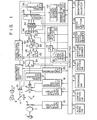
- the optical image of an object 1 is imaged on a photosensor 6 through an objective lens 2, aperture 3, half mirror 4 and shutter 5.
- the optical image is also imaged on a finder screen 7 through the half mirror 4.
- the optical image on the finder screen 7 can be viewed through a half mirror 11, prism 8 and eye-piece lens 9.
- a display image on a display 10 is projected to the half mirror 11 and can also be viewed through the eyepiece lens 9.
- a control device or microcomputer 12 serves to 'control the whole of an electronic photographing apparatus and has an auto/manual selection switch 13 connected thereto.
- the microcomputer 12 achieves automatic exposure photographing. More specifically, in response to the output signal of an external exposure metering circuit (not shown) or a full-area averaging circuit 14, the microcomputer 12 supplies control signals to an aperture control circuit 16, shutter speed control circuit 17, photosensor driving circuit 18, recording switch 19, and recording and reproducing section 20 every time the recording switch 15 is operated.
- the selection switch 13 is set to "manual”
- the microcomputer 12 reads the setpoints of the manual aperture and the shutter setting members 21 and 22, determines the aperture and shutter speed and records them every time the recording switch 19 is operated.
- a reproduction switch 23 is pushed, a reproduced video signal is read out of the recording and reproducing section 20, and a reproduction switch 24 is changed over from a contact 1 to another contact 2.
- An image confirmation switch 26 is operated in the case where the image needs only to be confirmed without being recorded. The following operation is carried out when switch 26 is operated.
- the switch 26 When the switch 26 is pushed, the optical image on the photosensor 6 under manually-set aperture and shutter speed is read out as an electric signal by the photosensor driver 18 :
- the electric signal is amplified by an amplifier A and supplied to a signal processing circuit 27 and converted to an NTSC standard composition video signal.
- the video signal is applied to comparators 28, 29, a video signal composition circuit 30, and the full-area averaging circuit 14 when the reproduction switch 24 contacts the contact cl.
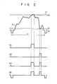
- the composition video signal Sl (Fig.
- the composition video signal supplied to the comparator 29 is converted to logic level 1 when it exceeds reference value VD which has been set slightly higher than its black level V2, or to the logic level 0 when it does not exceeds the reference value VD.
- AND gates 31 and 32 are provided to obtain binary signals S2 and S3 which are formed after removing the retracing signal components from the output signals of the comparators 28 and 29.
- the binary signals S2 and S3 may be used independently, or they may be applied to an OR gate 33 and converted to a binary signal S4.
- the binary signal S4 represents the poor quality image signal.
- the poor quality image signal S4 is supplied to the signal processing circuit 35 to be gain-controlled at a proper value and added with the synchronizing signal extracted from the original video signal.
- the signal processing circuit 35 produces a binary video signal S5 which represents a poor quality image, when a switch 34 is contacted with contact 1.
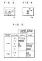
- a binary image which represents a poor quality image P2 shown in Fig. 4 is obtained when the image confirmation switch 26 is pushed.
- the person who is backlit is underexposed while the sun is overexposed.
- the binary video signal obtained from the signal processing circuit 35 is supplied to the video signal composition circuit 30 which supplies the binary video signal, output signal or analog video signal of the signal processing circuit 27 to the display 10 according to the selection made by the display image selection switch 36.
- the composition signal of both video signals is supplied to the display 10 where a composition image is displayed.
- a brightness adjusting circuit 37 is connected between the video signal composition circuit 30 and the display 10 to adjust the brightness of the display mage. If the display 10 is turned off, an image based on the optical finder can be viewed.
- an over- and/or underexposed binary image is two-dimensionally displayed in the electric finder or diplay 10 every time when the image confirmation switch 26 is pushed, because the analog video signal is converted to a binary video signal according to the white and black reference levels. Therefore, it can be judged reliably and speedily from the displayed binary image whether a picture to be photographed is correctly exposed or not.
- the photographing apparatus of the present invention can be applied to a specific photographing condition which can not be processed by the full-area averaging circuit. Since the latitude of video is narrower than that of film, the picture quality evaluation achieved by the present invention is useful.
- part of the finder screen or its central portion is masked and only the poor quality image signal in the important section of the image is processed as an effective signal.
- the picture elements are combined in a 2-by-2, or 3-by-3 section and only one or two poor quality elements are present in the section, these poor quality picture elements are ignored. Namely, if a few poor quality picture-elements in a micro-area they are made ineffective.
- Other poor quality picture elements left after the logical process are measured by a poor quality picture element integrating circuit (or a poor quality picture element counter) 40.
- Fig. 5 shows the conditions under which poor quality picture elements are caused in shutter-priority. According to Fig. 5, the best conditions are obtained in case A when the shutter speed is 1/250 sec., while the aperture is 4f. Similarly, in case B, the shutter speed can be 1/60 sec., while the aperture is 3.5f. This can be established in shutter-priority or program automation.
- the switch is contacted by one of the contacts 2, 3 or 4. It is difficult to determine the conditions when an artificial light source such as the electric flash device should be used.
- the poor quality image signal which represents the output of the OR circuit 33 may be stored in the binary image memory 42. For example, if a poor quality image signal obtained under a specific shutter speed and aperture is stored in an area M1 of the binary image memory 42, and other poor quality image signals obtained under other conditions with the switch 34 are then stored in areas M2 and M3 of the binary image memory 42. This process is similar to that of the stepping exposure often employed in photography. Where the result is stored in the binary image memory.
- the image logical circuit 39 which has done the image logical process, supplies its output signal to the display 10 via the signal processing circuit 35 to be displayed as a poor quality image.
- the photographer can judge accurately the latitude of an object on the finder screen at a wide range and can select the optimum photograhing condition. If, on the basis of the displayed image information, it is judged that the object to be photographed exceeds the latitude of video system, the same object can be recorded under plural photographing conditions. According to this system, the capacity of the memory can be reduced because the image signal is stored as a binary signal.
- a video signal is converted to binary video signals responsive to those reference levels which are close to its white and black levels.
- the binary video signals are then two-dimensionally displayed, as an over- and underexposed image. Therefore, the present invention enables the exposure to be speedily and accurately understood. As a result, the optimum value of the exposure can be determined, and automatic exposure control can be achieved.
- the apparatus of this invention eliminates the drawbacks of the prior art image pick-up system and can perform various photographing functions which have heretofore been impossible in the film camera. According to this invention, the following advantages are obtained:
- finder devices and image evaluation device applicable to, for example, an image measuring and image processing apparatus using an ITV camera, a video movie system, an electronic process apparatus, a TV camera, a VTR camera or an electronic steel camera.
- the operation switches and modes used in the embodiments of this invention may be replaced by another member and mode, respectively, depending upon the use to which they are put. According to this invention it is possible to use various kinds of circuit systems. It is also possible to use, for example, an optical disk, magnetic disk, magnetic tape or an image memory, such as a solid state memory as a recording/reproducing section.
- the two-dimensional display may be comprised of a liquid crystal display or a light emitting diode display.
- An optical filter which can form a properly viewable color contrast, may be provided on the whole surface of the display.
Priority Applications (2)
| Application Number | Priority Date | Filing Date | Title |
|---|---|---|---|
| DE8484101628T DE3473980D1 (en) | 1984-02-17 | 1984-02-17 | Electronic photographing apparatus |
| EP84101628A EP0152496B1 (fr) | 1984-02-17 | 1984-02-17 | Appareil photographique électronique |
Applications Claiming Priority (1)
| Application Number | Priority Date | Filing Date | Title |
|---|---|---|---|
| EP84101628A EP0152496B1 (fr) | 1984-02-17 | 1984-02-17 | Appareil photographique électronique |
Publications (2)
| Publication Number | Publication Date |
|---|---|
| EP0152496A1 true EP0152496A1 (fr) | 1985-08-28 |
| EP0152496B1 EP0152496B1 (fr) | 1988-09-07 |
Family
ID=8191778
Family Applications (1)
| Application Number | Title | Priority Date | Filing Date |
|---|---|---|---|
| EP84101628A Expired EP0152496B1 (fr) | 1984-02-17 | 1984-02-17 | Appareil photographique électronique |
Country Status (2)
| Country | Link |
|---|---|
| EP (1) | EP0152496B1 (fr) |
| DE (1) | DE3473980D1 (fr) |
Cited By (9)
| Publication number | Priority date | Publication date | Assignee | Title |
|---|---|---|---|---|
| EP0220859A2 (fr) * | 1985-10-30 | 1987-05-06 | Polaroid Corporation | Caméra et procédé d'imagerie |
| EP0379808A1 (fr) * | 1988-12-29 | 1990-08-01 | Nikon Corporation | Dispositif de détection de foyer |
| NL8902026A (nl) * | 1989-08-08 | 1991-03-01 | Samsung Electronics Co Ltd | Schakeling voor het opwekken van een zebrasignaal voor een videocamera. |
| EP0507349A2 (fr) * | 1991-04-05 | 1992-10-07 | Matsushita Electric Industrial Co., Ltd. | Contrôle de la zone photométrique d'un dispositif de prises d'images |
| WO1993002523A1 (fr) * | 1991-07-15 | 1993-02-04 | Eastman Kodak Company | Systeme indiquant les zones surexposees d'une image |
| EP0535829A2 (fr) * | 1991-09-30 | 1993-04-07 | Sony Corporation | Réglage de l'équilibrage de noir pour des caméras vidéo munies de plusieurs capteurs d'images à l'état solide |
| EP0707419A2 (fr) * | 1995-11-10 | 1996-04-17 | Sinar AG Schaffhausen | Méthode pour la génération de l'image d'un viseur et caméra à image fixe |
| EP0680724A3 (fr) * | 1990-10-12 | 1997-09-24 | Nippon Kogaku Kk | Caméra capable de détecter un regard. |
| EP1560424A2 (fr) | 2004-01-30 | 2005-08-03 | Arnold & Richter Cine Technik Gmbh & Co. Betriebs Kg | Caméra cinématographique électronique |
Citations (4)
| Publication number | Priority date | Publication date | Assignee | Title |
|---|---|---|---|---|
| DE2216949B1 (de) * | 1972-04-08 | 1973-07-26 | Robert Bosch Fernsehanlagen Gmbh, 6100 Darmstadt | Fernsehkamera |
| US4262301A (en) * | 1978-03-30 | 1981-04-14 | Polaroid Corporation | Electronic imaging camera |
| US4303322A (en) * | 1979-11-29 | 1981-12-01 | Canon Kabushiki Kaisha | Electronic image pick-up device for a single-lens reflex camera having an interchangeable finder |
| EP0080350A1 (fr) * | 1981-11-25 | 1983-06-01 | Crosfield Electronics Limited | Reproduction d'images |
-
1984
- 1984-02-17 DE DE8484101628T patent/DE3473980D1/de not_active Expired
- 1984-02-17 EP EP84101628A patent/EP0152496B1/fr not_active Expired
Patent Citations (4)
| Publication number | Priority date | Publication date | Assignee | Title |
|---|---|---|---|---|
| DE2216949B1 (de) * | 1972-04-08 | 1973-07-26 | Robert Bosch Fernsehanlagen Gmbh, 6100 Darmstadt | Fernsehkamera |
| US4262301A (en) * | 1978-03-30 | 1981-04-14 | Polaroid Corporation | Electronic imaging camera |
| US4303322A (en) * | 1979-11-29 | 1981-12-01 | Canon Kabushiki Kaisha | Electronic image pick-up device for a single-lens reflex camera having an interchangeable finder |
| EP0080350A1 (fr) * | 1981-11-25 | 1983-06-01 | Crosfield Electronics Limited | Reproduction d'images |
Cited By (20)
| Publication number | Priority date | Publication date | Assignee | Title |
|---|---|---|---|---|
| EP0220859A3 (en) * | 1985-10-30 | 1988-09-28 | Polaroid Corporation | Imaging camera and method |
| EP0220859A2 (fr) * | 1985-10-30 | 1987-05-06 | Polaroid Corporation | Caméra et procédé d'imagerie |
| EP0379808A1 (fr) * | 1988-12-29 | 1990-08-01 | Nikon Corporation | Dispositif de détection de foyer |
| NL8902026A (nl) * | 1989-08-08 | 1991-03-01 | Samsung Electronics Co Ltd | Schakeling voor het opwekken van een zebrasignaal voor een videocamera. |
| EP0680724A3 (fr) * | 1990-10-12 | 1997-09-24 | Nippon Kogaku Kk | Caméra capable de détecter un regard. |
| US5280359A (en) * | 1991-04-05 | 1994-01-18 | Matsushita Electric Industrial Co., Ltd. | Image pick-up device with auto lens control for freely selecting photometric area |
| EP0507349A2 (fr) * | 1991-04-05 | 1992-10-07 | Matsushita Electric Industrial Co., Ltd. | Contrôle de la zone photométrique d'un dispositif de prises d'images |
| EP0507349A3 (en) * | 1991-04-05 | 1993-05-19 | Matsushita Electric Industrial Co., Ltd. | Control of the photometric area of an image pickup device |
| WO1993002523A1 (fr) * | 1991-07-15 | 1993-02-04 | Eastman Kodak Company | Systeme indiquant les zones surexposees d'une image |
| US5283655A (en) * | 1991-09-30 | 1994-02-01 | Sony Corporation | Video camera apparatus having solid state imager |
| EP0535829A3 (en) * | 1991-09-30 | 1993-09-08 | Sony Corporation | Black balance adjustment for video cameras having several solid-state imager |
| EP0535829A2 (fr) * | 1991-09-30 | 1993-04-07 | Sony Corporation | Réglage de l'équilibrage de noir pour des caméras vidéo munies de plusieurs capteurs d'images à l'état solide |
| KR100299200B1 (ko) * | 1991-09-30 | 2001-10-22 | 이데이 노부유끼 | 비디오카메라장치 |
| EP0707419A2 (fr) * | 1995-11-10 | 1996-04-17 | Sinar AG Schaffhausen | Méthode pour la génération de l'image d'un viseur et caméra à image fixe |
| EP0707419A3 (fr) * | 1995-11-10 | 1996-05-29 | Sinar Ag Schaffhausen | |
| EP1560424A2 (fr) | 2004-01-30 | 2005-08-03 | Arnold & Richter Cine Technik Gmbh & Co. Betriebs Kg | Caméra cinématographique électronique |
| EP1560424A3 (fr) * | 2004-01-30 | 2008-04-23 | Arnold & Richter Cine Technik Gmbh & Co. Betriebs Kg | Caméra cinématographique électronique |
| US7428381B2 (en) | 2004-01-30 | 2008-09-23 | Arnold & Richter Cine Technik Gmbh & Co. Betriebs Kg | Electronic motion picture camera |
| US8013924B2 (en) | 2004-01-30 | 2011-09-06 | Arnold & Richter Cine Technik Gmbh & Co. Betriebs Kg | Electronic motion picture camera |
| DE102004004806B4 (de) * | 2004-01-30 | 2012-04-19 | Arnold & Richter Cine Technik Gmbh & Co. Betriebs Kg | Elektronische Laufbildkamera |
Also Published As
| Publication number | Publication date |
|---|---|
| DE3473980D1 (en) | 1988-10-13 |
| EP0152496B1 (fr) | 1988-09-07 |
Similar Documents
| Publication | Publication Date | Title |
|---|---|---|
| US4584610A (en) | Electronic photographing apparatus | |
| JP3540485B2 (ja) | 電子スチルカメラ | |
| US20060067670A1 (en) | Imaging device | |
| JPH0431474B2 (fr) | ||
| EP0152496B1 (fr) | Appareil photographique électronique | |
| JPH0738801A (ja) | 撮像装置 | |
| JP2528368B2 (ja) | カメラ | |
| GB2233465A (en) | "Zoom lens camera" | |
| US4879600A (en) | Image sensing apparatus with control for varying the readout methodology | |
| US4763196A (en) | Image sensing device | |
| JPH08205021A (ja) | 画像入力装置 | |
| EP0905964A2 (fr) | Lecteur de film | |
| US5258847A (en) | Object tracing device | |
| JP2935116B2 (ja) | 撮像装置 | |
| JPS58153464A (ja) | 固体撮像素子を使用したスチルカメラ | |
| JP3470231B2 (ja) | スチルビデオカメラ | |
| JPH05260372A (ja) | 画像読み取り装置 | |
| JPH11150679A (ja) | 撮像装置および記録媒体 | |
| JP2580105B2 (ja) | 電子カメラ | |
| JP2002064728A (ja) | ディジタル・スチル・カメラおよび露出量表示制御方法 | |
| JP3500768B2 (ja) | オートホワイトバランス装置 | |
| JPH0728381B2 (ja) | 電子的撮像装置 | |
| JPH06101847B2 (ja) | 撮像装置 | |
| JP2003143487A (ja) | 撮像装置 | |
| JPH02141072A (ja) | 電子スチルカメラ |
Legal Events
| Date | Code | Title | Description |
|---|---|---|---|
| PUAI | Public reference made under article 153(3) epc to a published international application that has entered the european phase |
Free format text: ORIGINAL CODE: 0009012 |
|
| 17P | Request for examination filed |
Effective date: 19841218 |
|
| AK | Designated contracting states |
Designated state(s): DE FR GB IT NL |
|
| 17Q | First examination report despatched |
Effective date: 19870128 |
|
| GRAA | (expected) grant |
Free format text: ORIGINAL CODE: 0009210 |
|
| AK | Designated contracting states |
Kind code of ref document: B1 Designated state(s): DE FR GB IT NL |
|
| PG25 | Lapsed in a contracting state [announced via postgrant information from national office to epo] |
Ref country code: NL Effective date: 19880907 Ref country code: IT Free format text: LAPSE BECAUSE OF FAILURE TO SUBMIT A TRANSLATION OF THE DESCRIPTION OR TO PAY THE FEE WITHIN THE PRESCRIBED TIME-LIMIT;WARNING: LAPSES OF ITALIAN PATENTS WITH EFFECTIVE DATE BEFORE 2007 MAY HAVE OCCURRED AT ANY TIME BEFORE 2007. THE CORRECT EFFECTIVE DATE MAY BE DIFFERENT FROM THE ONE RECORDED. Effective date: 19880907 |
|
| REF | Corresponds to: |
Ref document number: 3473980 Country of ref document: DE Date of ref document: 19881013 |
|
| ET | Fr: translation filed | ||
| NLV1 | Nl: lapsed or annulled due to failure to fulfill the requirements of art. 29p and 29m of the patents act | ||
| PLBE | No opposition filed within time limit |
Free format text: ORIGINAL CODE: 0009261 |
|
| STAA | Information on the status of an ep patent application or granted ep patent |
Free format text: STATUS: NO OPPOSITION FILED WITHIN TIME LIMIT |
|
| 26N | No opposition filed | ||
| PGFP | Annual fee paid to national office [announced via postgrant information from national office to epo] |
Ref country code: DE Payment date: 19991231 Year of fee payment: 17 |
|
| PGFP | Annual fee paid to national office [announced via postgrant information from national office to epo] |
Ref country code: FR Payment date: 20000210 Year of fee payment: 17 |
|
| PGFP | Annual fee paid to national office [announced via postgrant information from national office to epo] |
Ref country code: GB Payment date: 20000216 Year of fee payment: 17 |
|
| PG25 | Lapsed in a contracting state [announced via postgrant information from national office to epo] |
Ref country code: GB Free format text: LAPSE BECAUSE OF NON-PAYMENT OF DUE FEES Effective date: 20010217 |
|
| GBPC | Gb: european patent ceased through non-payment of renewal fee |
Effective date: 20010217 |
|
| PG25 | Lapsed in a contracting state [announced via postgrant information from national office to epo] |
Ref country code: FR Free format text: LAPSE BECAUSE OF NON-PAYMENT OF DUE FEES Effective date: 20011031 |
|
| REG | Reference to a national code |
Ref country code: FR Ref legal event code: ST |
|
| PG25 | Lapsed in a contracting state [announced via postgrant information from national office to epo] |
Ref country code: DE Free format text: LAPSE BECAUSE OF NON-PAYMENT OF DUE FEES Effective date: 20011201 |