EP0152320B1 - Leichter Lagewagen mit einem Behälter und zwei Rädern - Google Patents
Leichter Lagewagen mit einem Behälter und zwei Rädern Download PDFInfo
- Publication number
- EP0152320B1 EP0152320B1 EP85400106A EP85400106A EP0152320B1 EP 0152320 B1 EP0152320 B1 EP 0152320B1 EP 85400106 A EP85400106 A EP 85400106A EP 85400106 A EP85400106 A EP 85400106A EP 0152320 B1 EP0152320 B1 EP 0152320B1
- Authority
- EP
- European Patent Office
- Prior art keywords
- wheels
- tub
- bearing members
- arrangement
- bucket
- Prior art date
- Legal status (The legal status is an assumption and is not a legal conclusion. Google has not performed a legal analysis and makes no representation as to the accuracy of the status listed.)
- Expired
Links
- 238000010276 construction Methods 0.000 description 12
- 239000000463 material Substances 0.000 description 6
- 238000005096 rolling process Methods 0.000 description 5
- 239000002184 metal Substances 0.000 description 3
- 238000009418 renovation Methods 0.000 description 2
- 230000035515 penetration Effects 0.000 description 1
Images


Classifications
-
- B—PERFORMING OPERATIONS; TRANSPORTING
- B62—LAND VEHICLES FOR TRAVELLING OTHERWISE THAN ON RAILS
- B62B—HAND-PROPELLED VEHICLES, e.g. HAND CARTS OR PERAMBULATORS; SLEDGES
- B62B1/00—Hand carts having only one axis carrying one or more transport wheels; Equipment therefor
- B62B1/10—Hand carts having only one axis carrying one or more transport wheels; Equipment therefor in which the load is intended to be transferred totally to the wheels
- B62B1/12—Hand carts having only one axis carrying one or more transport wheels; Equipment therefor in which the load is intended to be transferred totally to the wheels involving parts being adjustable, collapsible, attachable, detachable, or convertible
-
- B—PERFORMING OPERATIONS; TRANSPORTING
- B62—LAND VEHICLES FOR TRAVELLING OTHERWISE THAN ON RAILS
- B62B—HAND-PROPELLED VEHICLES, e.g. HAND CARTS OR PERAMBULATORS; SLEDGES
- B62B1/00—Hand carts having only one axis carrying one or more transport wheels; Equipment therefor
- B62B1/10—Hand carts having only one axis carrying one or more transport wheels; Equipment therefor in which the load is intended to be transferred totally to the wheels
Definitions
- the present invention relates to construction vehicles and, in particular, light vehicles supplying materials.
- a wheelbarrow of the type comprising a dumper, with one or two wheels, fitted with stretchers has a large footprint given the useful volume proposed for handling loads.
- this space becomes a major drawback.
- the stretchers and the wheel protruding beyond the dumper reduce the possibilities of maneuvering the machine, preventing it from taking turns in too narrow corridors or the passage of adjoining doors.
- the present invention overcomes these drawbacks and indeed provides a new construction vehicle.
- the new construction vehicle comprises, as is conventional, a bucket and two wheels arranged coaxially on either side of the bucket.
- said bucket fits into the fictitious cylinder formed by said wheels and, the bucket being provided with two sets of rolling elements protruding on either side of the latter, each wheel having a rolling track and guide means, each set of rolling elements cooperates with a track and the guide means of each of the wheels in order to ensure both the cohesion of the assembly and the free rotation of the bucket relative to the wheels.
- This new vehicle particularly suitable for use in the field of rehabilitation has various advantages. Indeed, this new machine proposes to solve the problems posed by the transport of materials from a delivery point to a point of use whatever the difficulties of the journey may be, this without other handling of the materials than a loading and unloading performed at these two points, thereby reducing the loss of time, energy and, consequently, costs.
- the new vehicle keeps its load in balance regardless of its vertical or horizontal movement, thereby preventing any accidental spillage.
- a rotation of the wheels during a movement causes a rotation of the bearing elements, so as to transform the rotational and translational movement of the wheels into a simple translational movement of the bucket.
- the new vehicle can travel both on a vertical plane (the ground) and on a horizontal plane (a facade) and thus make all possible movements without the need to tranship the load.
- the construction vehicle according to the invention essentially comprises a bucket 1 and two wheels 2 and 3.
- the bucket 1 is made up of twelve metal tubes placed so as to form the edges of a rectangular parallelepiped, said tubes forming beams, the cross members and the uprights of said parallelepiped.
- the bucket has a floor 4 capable of receiving the load, which is disposed between the four lower tubes, a handling ring 5 forming a loop between the two upper side members, and four attachment points 6 at the bottom of the uprights, which are suitable to receive traction means on either side of the bucket 1.
- the bucket further comprises eight rolling elements 7, in this case eight rollers arranged at the eight corners of the bucket, the axes of said rollers 7 being parallel to the transverse axis of the bucket. Said rollers are broken down, with respect to the plane of symmetry defined by the longitudinal and vertical axes, into two sets of four rollers 8 and 9, the centers of the rollers of each set falling within a fictitious circumference.
- the wheels 2 and 3 have a cross section in the shape of a crown.
- the wheels 2 and 3 are arranged coaxially on the transverse axis, on either side of the bucket 1, said bucket 1 coming to be inscribed in the fictitious cylinder formed by said wheels 2 and 3.
- Each set of rollers 8 and 9 cooperates with the groove 10 of the associated wheel in order to ensure, thanks to the guide means, the cohesion of the assembly, and, thanks to the raceway, the free rotation of the bucket relative to the wheels.
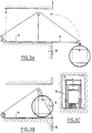
- the construction vehicle according to the invention comprises, in addition to a bucket 1 of parallelepipedal shape provided with a floor 4 and a handling ring 5, six elements 7, in this case six rollers decomposing into two sets of three rollers along the plane of symmetry defined by the longitudinal axis and the transverse axis, the axes of the rollers 7 of each set being parallel to the transverse axis of bucket 1, their center being inscribed on a fictitious circumference.
- rollers 7 of each assembly are angularly distributed in a regular manner with respect to the transverse axis, two rollers 10 being arranged at the lower corners of the bucket in order to distribute the load over two spans, the third roller 11 being fixed to the end of a metal tube 12 disposed vertically to the right of the upper and lower beams.
- This metal tube 12 is provided with means for adjusting its length 13, in this case two tubes mounted telescopically one inside the other, an adjustment screw making it possible to secure the latter.
- a lifting device can be associated with the vehicle according to the invention in order to allow the latter to enter the interior of a building by an opening located on the front.
- This device facilitates the passage of obstacles such as balconies or wall parts without having to considerably increase the length of the bracket overhanging the facade.
- the lifting device comprises a fixed console 14 in the form of a T placed on the wings, the end of the core of the T comprising a pulley, a mobile console 15 mounted on the end of a wing of the T projecting above the beyond building 16, said mobile console being provided at its end with a pulley, and a cable passing through the two pulleys connected at one of its ends to the load, the construction vehicle, and to the other at a means d 'training.
- the shape of the bucket 1 is in no way limiting, this rectangular shape being only one example which has the advantage of having great rigidity, a cylindrical or prismatic shape which can advantageously replace the latter, the characteristic sought. being to present a large useful volume while ensuring sufficient ground clearance.
Landscapes
- Engineering & Computer Science (AREA)
- Chemical & Material Sciences (AREA)
- Combustion & Propulsion (AREA)
- Transportation (AREA)
- Mechanical Engineering (AREA)
- Handcart (AREA)
- Motorcycle And Bicycle Frame (AREA)
- Automatic Cycles, And Cycles In General (AREA)
- Dental Tools And Instruments Or Auxiliary Dental Instruments (AREA)
- Purses, Travelling Bags, Baskets, Or Suitcases (AREA)
Claims (6)
Priority Applications (1)
| Application Number | Priority Date | Filing Date | Title |
|---|---|---|---|
| AT85400106T ATE28604T1 (de) | 1984-02-03 | 1985-01-23 | Leichter lagewagen mit einem behaelter und zwei raedern. |
Applications Claiming Priority (2)
| Application Number | Priority Date | Filing Date | Title |
|---|---|---|---|
| FR8401691 | 1984-02-03 | ||
| FR8401691A FR2559115B1 (fr) | 1984-02-03 | 1984-02-03 | Vehicule leger de chantier, du type comportant une benne et deux roues |
Publications (3)
| Publication Number | Publication Date |
|---|---|
| EP0152320A2 EP0152320A2 (de) | 1985-08-21 |
| EP0152320A3 EP0152320A3 (en) | 1985-09-18 |
| EP0152320B1 true EP0152320B1 (de) | 1987-07-29 |
Family
ID=9300745
Family Applications (1)
| Application Number | Title | Priority Date | Filing Date |
|---|---|---|---|
| EP85400106A Expired EP0152320B1 (de) | 1984-02-03 | 1985-01-23 | Leichter Lagewagen mit einem Behälter und zwei Rädern |
Country Status (4)
| Country | Link |
|---|---|
| EP (1) | EP0152320B1 (de) |
| AT (1) | ATE28604T1 (de) |
| DE (1) | DE3560388D1 (de) |
| FR (1) | FR2559115B1 (de) |
Families Citing this family (1)
| Publication number | Priority date | Publication date | Assignee | Title |
|---|---|---|---|---|
| DE19940913A1 (de) * | 1999-08-28 | 2001-03-01 | Roland Schueller | Bewegungsvorrichtung, insbesondere Rollmöbel |
Family Cites Families (3)
| Publication number | Priority date | Publication date | Assignee | Title |
|---|---|---|---|---|
| DE221544C (de) * | ||||
| US1885795A (en) * | 1931-01-03 | 1932-11-01 | Earl M Barrows | Vehicle |
| US2522894A (en) * | 1947-03-04 | 1950-09-19 | Roy E Putman | Handcart for milk cans and the like |
-
1984
- 1984-02-03 FR FR8401691A patent/FR2559115B1/fr not_active Expired
-
1985
- 1985-01-23 DE DE8585400106T patent/DE3560388D1/de not_active Expired
- 1985-01-23 AT AT85400106T patent/ATE28604T1/de not_active IP Right Cessation
- 1985-01-23 EP EP85400106A patent/EP0152320B1/de not_active Expired
Also Published As
| Publication number | Publication date |
|---|---|
| EP0152320A2 (de) | 1985-08-21 |
| FR2559115A1 (fr) | 1985-08-09 |
| DE3560388D1 (en) | 1987-09-03 |
| FR2559115B1 (fr) | 1986-07-11 |
| ATE28604T1 (de) | 1987-08-15 |
| EP0152320A3 (en) | 1985-09-18 |
Similar Documents
| Publication | Publication Date | Title |
|---|---|---|
| EP0737630A1 (de) | Selbstangetriebener Wagen mit teleskopischen Gabeln zur Handhabung von palettierten Lasten in Lagern und Warenlager | |
| CA2170385A1 (fr) | Installation mecanisee automatique de stockage d'objets | |
| EP1486452A2 (de) | System zum Heben und Stabilisieren von einem hängenden Lastträger | |
| EP0755841B1 (de) | Lastförderwagen | |
| EP0199652A1 (de) | Container-Verladevorrichtung | |
| FR2623891A1 (fr) | Installation pour briqueter la paroi interieure d'une enceinte | |
| EP0152320B1 (de) | Leichter Lagewagen mit einem Behälter und zwei Rädern | |
| CA2966965A1 (fr) | Pietement roulant pour un mat telescopique d'un appareil de levage de plaques, appareil muni d'un tel pietement, et procede de mise en oeuvre | |
| FR2478611A1 (fr) | Verrou mat de roulement de chariot elevateur a fourche | |
| EP0082046B1 (de) | Flaschenzüge | |
| FR2625488A1 (fr) | Dispositif de levage mecanique telescopique | |
| WO1990012707A1 (fr) | Appareil de manutention automatique de charges allongees sur le toit d'un vehicule | |
| FR2536735A1 (fr) | Chariot de travail notamment pour la pose des vitres de toitures des serres agricoles | |
| EP0490798A2 (de) | Kran, insbesondere für die Handhabung | |
| FR2593201A1 (fr) | Machine a poser des bordures de trottoir | |
| FR3067707B1 (fr) | Transpalette | |
| FR2698856A1 (fr) | Dispositif de guidage de câble pour un treuil, en particulier un treuil de levage. | |
| FR2490166A1 (fr) | Vehicule equipe de dispositifs de transbordement lateral de conteneurs | |
| EP0725020B1 (de) | System zum lenkbaren Rollen einer Schwerlast | |
| FR2856647A1 (fr) | Dispositif de manutention de poubelle pour ordures menageres | |
| EP0911294A1 (de) | Schwingungsdämpfungsvorrichtung für Hubgerät mit kreuzenden Seilen | |
| FR2469339A1 (fr) | Vehicule triporteur utilisable notamment comme appareil de culture et de ramassage de produits agricoles et autres | |
| EP1849720A1 (de) | Mobile vertikale Speichervorrichtung | |
| FR2609745A1 (fr) | Dispositif de manutention pour branches destinees au coffrage de voiles de beton | |
| FR2539684A1 (fr) | Dispositif de transport de charges |
Legal Events
| Date | Code | Title | Description |
|---|---|---|---|
| PUAI | Public reference made under article 153(3) epc to a published international application that has entered the european phase |
Free format text: ORIGINAL CODE: 0009012 |
|
| PUAL | Search report despatched |
Free format text: ORIGINAL CODE: 0009013 |
|
| AK | Designated contracting states |
Designated state(s): AT BE CH DE FR GB IT LI LU NL SE |
|
| AK | Designated contracting states |
Designated state(s): AT BE CH DE FR GB IT LI LU NL SE |
|
| 17P | Request for examination filed |
Effective date: 19851216 |
|
| 17Q | First examination report despatched |
Effective date: 19861020 |
|
| GRAA | (expected) grant |
Free format text: ORIGINAL CODE: 0009210 |
|
| ITF | It: translation for a ep patent filed | ||
| AK | Designated contracting states |
Kind code of ref document: B1 Designated state(s): AT BE CH DE FR GB IT LI LU NL SE |
|
| PG25 | Lapsed in a contracting state [announced via postgrant information from national office to epo] |
Ref country code: AT Effective date: 19870729 |
|
| REF | Corresponds to: |
Ref document number: 28604 Country of ref document: AT Date of ref document: 19870815 Kind code of ref document: T |
|
| REF | Corresponds to: |
Ref document number: 3560388 Country of ref document: DE Date of ref document: 19870903 |
|
| PG25 | Lapsed in a contracting state [announced via postgrant information from national office to epo] |
Ref country code: LU Free format text: LAPSE BECAUSE OF NON-PAYMENT OF DUE FEES Effective date: 19880131 |
|
| PLBE | No opposition filed within time limit |
Free format text: ORIGINAL CODE: 0009261 |
|
| STAA | Information on the status of an ep patent application or granted ep patent |
Free format text: STATUS: NO OPPOSITION FILED WITHIN TIME LIMIT |
|
| 26N | No opposition filed | ||
| PGFP | Annual fee paid to national office [announced via postgrant information from national office to epo] |
Ref country code: FR Payment date: 19891229 Year of fee payment: 6 |
|
| PGFP | Annual fee paid to national office [announced via postgrant information from national office to epo] |
Ref country code: CH Payment date: 19900115 Year of fee payment: 6 |
|
| PGFP | Annual fee paid to national office [announced via postgrant information from national office to epo] |
Ref country code: DE Payment date: 19900122 Year of fee payment: 6 |
|
| PGFP | Annual fee paid to national office [announced via postgrant information from national office to epo] |
Ref country code: SE Payment date: 19900125 Year of fee payment: 6 |
|
| ITTA | It: last paid annual fee | ||
| PGFP | Annual fee paid to national office [announced via postgrant information from national office to epo] |
Ref country code: NL Payment date: 19900131 Year of fee payment: 6 Ref country code: LU Payment date: 19900131 Year of fee payment: 6 Ref country code: GB Payment date: 19900131 Year of fee payment: 6 |
|
| PGFP | Annual fee paid to national office [announced via postgrant information from national office to epo] |
Ref country code: BE Payment date: 19900213 Year of fee payment: 6 |
|
| PG25 | Lapsed in a contracting state [announced via postgrant information from national office to epo] |
Ref country code: GB Effective date: 19910123 |
|
| PG25 | Lapsed in a contracting state [announced via postgrant information from national office to epo] |
Ref country code: SE Effective date: 19910124 |
|
| PG25 | Lapsed in a contracting state [announced via postgrant information from national office to epo] |
Ref country code: LI Effective date: 19910131 Ref country code: CH Effective date: 19910131 Ref country code: BE Effective date: 19910131 |
|
| PG25 | Lapsed in a contracting state [announced via postgrant information from national office to epo] |
Ref country code: NL Effective date: 19910801 |
|
| NLV4 | Nl: lapsed or anulled due to non-payment of the annual fee | ||
| GBPC | Gb: european patent ceased through non-payment of renewal fee | ||
| PG25 | Lapsed in a contracting state [announced via postgrant information from national office to epo] |
Ref country code: FR Effective date: 19910930 |
|
| REG | Reference to a national code |
Ref country code: CH Ref legal event code: PL |
|
| PG25 | Lapsed in a contracting state [announced via postgrant information from national office to epo] |
Ref country code: DE Effective date: 19911001 |
|
| REG | Reference to a national code |
Ref country code: FR Ref legal event code: ST |
|
| EUG | Se: european patent has lapsed |
Ref document number: 85400106.2 Effective date: 19910910 |