EP0152016A1 - Method and apparatus for the continuous production of reinforced manufactured cement products - Google Patents
Method and apparatus for the continuous production of reinforced manufactured cement products Download PDFInfo
- Publication number
- EP0152016A1 EP0152016A1 EP85100972A EP85100972A EP0152016A1 EP 0152016 A1 EP0152016 A1 EP 0152016A1 EP 85100972 A EP85100972 A EP 85100972A EP 85100972 A EP85100972 A EP 85100972A EP 0152016 A1 EP0152016 A1 EP 0152016A1
- Authority
- EP
- European Patent Office
- Prior art keywords
- mesh
- cement
- manufactured
- weight
- spraying
- Prior art date
- Legal status (The legal status is an assumption and is not a legal conclusion. Google has not performed a legal analysis and makes no representation as to the accuracy of the status listed.)
- Granted
Links
- 239000004568 cement Substances 0.000 title claims abstract description 59
- 238000000034 method Methods 0.000 title claims abstract description 29
- 238000010924 continuous production Methods 0.000 title claims abstract description 8
- 239000004033 plastic Substances 0.000 claims abstract description 17
- 229920003023 plastic Polymers 0.000 claims abstract description 17
- 238000005507 spraying Methods 0.000 claims abstract description 11
- 239000004744 fabric Substances 0.000 claims abstract description 10
- 239000004743 Polypropylene Substances 0.000 claims abstract description 7
- -1 polypropylene Polymers 0.000 claims abstract description 7
- 229920001155 polypropylene Polymers 0.000 claims abstract description 7
- 239000000203 mixture Substances 0.000 claims description 35
- XLYOFNOQVPJJNP-UHFFFAOYSA-N water Substances O XLYOFNOQVPJJNP-UHFFFAOYSA-N 0.000 claims description 11
- 239000000463 material Substances 0.000 claims description 5
- 238000004519 manufacturing process Methods 0.000 claims description 3
- 229920000098 polyolefin Polymers 0.000 claims description 2
- 239000002985 plastic film Substances 0.000 claims 1
- 229920006255 plastic film Polymers 0.000 claims 1
- 238000005470 impregnation Methods 0.000 description 10
- 239000010410 layer Substances 0.000 description 9
- 230000015572 biosynthetic process Effects 0.000 description 8
- 239000007921 spray Substances 0.000 description 7
- 238000012360 testing method Methods 0.000 description 7
- 239000010425 asbestos Substances 0.000 description 4
- 238000005452 bending Methods 0.000 description 4
- 229910052895 riebeckite Inorganic materials 0.000 description 4
- 238000000151 deposition Methods 0.000 description 3
- 229910000831 Steel Inorganic materials 0.000 description 2
- 239000011230 binding agent Substances 0.000 description 2
- 238000006073 displacement reaction Methods 0.000 description 2
- 238000009499 grossing Methods 0.000 description 2
- 238000012423 maintenance Methods 0.000 description 2
- 239000004576 sand Substances 0.000 description 2
- 239000010959 steel Substances 0.000 description 2
- 235000008733 Citrus aurantifolia Nutrition 0.000 description 1
- 239000004952 Polyamide Substances 0.000 description 1
- 235000011941 Tilia x europaea Nutrition 0.000 description 1
- 239000000654 additive Substances 0.000 description 1
- 238000000889 atomisation Methods 0.000 description 1
- 206010061592 cardiac fibrillation Diseases 0.000 description 1
- 239000003795 chemical substances by application Substances 0.000 description 1
- 230000006835 compression Effects 0.000 description 1
- 238000007906 compression Methods 0.000 description 1
- 238000009826 distribution Methods 0.000 description 1
- 239000011518 fibre cement Substances 0.000 description 1
- 230000002600 fibrillogenic effect Effects 0.000 description 1
- 239000002657 fibrous material Substances 0.000 description 1
- 239000000945 filler Substances 0.000 description 1
- 230000003311 flocculating effect Effects 0.000 description 1
- 239000010881 fly ash Substances 0.000 description 1
- 239000010440 gypsum Substances 0.000 description 1
- 229910052602 gypsum Inorganic materials 0.000 description 1
- 238000009776 industrial production Methods 0.000 description 1
- 239000004571 lime Substances 0.000 description 1
- 230000035515 penetration Effects 0.000 description 1
- 239000000049 pigment Substances 0.000 description 1
- 229920002647 polyamide Polymers 0.000 description 1
- 238000002360 preparation method Methods 0.000 description 1
- 238000003825 pressing Methods 0.000 description 1
- QQONPFPTGQHPMA-UHFFFAOYSA-N propylene Natural products CC=C QQONPFPTGQHPMA-UHFFFAOYSA-N 0.000 description 1
- 125000004805 propylene group Chemical group [H]C([H])([H])C([H])([*:1])C([H])([H])[*:2] 0.000 description 1
- 239000008262 pumice Substances 0.000 description 1
- 230000002787 reinforcement Effects 0.000 description 1
- 230000003014 reinforcing effect Effects 0.000 description 1
- 239000002344 surface layer Substances 0.000 description 1
- 230000001360 synchronised effect Effects 0.000 description 1
- 229920001059 synthetic polymer Polymers 0.000 description 1
- 230000001988 toxicity Effects 0.000 description 1
- 231100000419 toxicity Toxicity 0.000 description 1
- 230000036967 uncompetitive effect Effects 0.000 description 1
- 238000009827 uniform distribution Methods 0.000 description 1
Images

Classifications
-
- B—PERFORMING OPERATIONS; TRANSPORTING
- B28—WORKING CEMENT, CLAY, OR STONE
- B28B—SHAPING CLAY OR OTHER CERAMIC COMPOSITIONS; SHAPING SLAG; SHAPING MIXTURES CONTAINING CEMENTITIOUS MATERIAL, e.g. PLASTER
- B28B23/00—Arrangements specially adapted for the production of shaped articles with elements wholly or partly embedded in the moulding material; Production of reinforced objects
- B28B23/0006—Arrangements specially adapted for the production of shaped articles with elements wholly or partly embedded in the moulding material; Production of reinforced objects the reinforcement consisting of aligned, non-metal reinforcing elements
-
- B—PERFORMING OPERATIONS; TRANSPORTING
- B28—WORKING CEMENT, CLAY, OR STONE
- B28B—SHAPING CLAY OR OTHER CERAMIC COMPOSITIONS; SHAPING SLAG; SHAPING MIXTURES CONTAINING CEMENTITIOUS MATERIAL, e.g. PLASTER
- B28B23/00—Arrangements specially adapted for the production of shaped articles with elements wholly or partly embedded in the moulding material; Production of reinforced objects
-
- C—CHEMISTRY; METALLURGY
- C04—CEMENTS; CONCRETE; ARTIFICIAL STONE; CERAMICS; REFRACTORIES
- C04B—LIME, MAGNESIA; SLAG; CEMENTS; COMPOSITIONS THEREOF, e.g. MORTARS, CONCRETE OR LIKE BUILDING MATERIALS; ARTIFICIAL STONE; CERAMICS; REFRACTORIES; TREATMENT OF NATURAL STONE
- C04B16/00—Use of organic materials as fillers, e.g. pigments, for mortars, concrete or artificial stone; Treatment of organic materials specially adapted to enhance their filling properties in mortars, concrete or artificial stone
- C04B16/04—Macromolecular compounds
- C04B16/06—Macromolecular compounds fibrous
- C04B16/0608—Fibrilles, e.g. fibrillated films
Definitions
- This invention relates to a method and apparatus for the continuous production of manufactured cement products reinforced by means of mesh obtained from fibrillated plastics film.
- the invention relates to a method and relative apparatus for the continuous production of products manufactured from cement mixes and reinforced by means of mesh obtained from plastics film, in which the mesh is incorporated into the mix by spraying said mix on to the mesh, which is made to continuously advance by moving along a horizontal plane rigid with a cloth or felt support, said cement mix being sprayed on to the continuously advancing mesh such that it becomes distributed uniformly over the mesh.
- cement mix or more simply the term “cement” indicates in the present description a mix consisting exclusively or mainly of one or more binders such as cement, lime and pozzolan, white gypsum binder and the like, with water.
- plastics film mesh or more simply “mesh” indicates in the present description any mesh obtained by treating continuous film, and in particular the mesh obtained by fibrillation for example as described in Italian patent application No. 9504A/77.
- the method and apparatus according to the present invention produce reinforced manufactured cement products such as flat or corrugated slabs, panels, tubes etc., which advantagely replace analogous manufactured asbestos cement products.
- asbestos has the serious drawback of possessing toxicity characteristics, because of which it constitutes a danger to the health both of those workers who extract the material, and of users who are required to cut or saw manufactured cement products containing asbestos fibres.
- Italian patent application No. 9504A/77 describes the preparation of manufactured cement products reinforced by means of a mesh constituted by a fibrillated plastics film.
- this description offers no teaching regarding the method for obtaining the manufactured product, of which only a few samples are produced on a laboratory scale by methods which resemble manual methods and are in all cases discontinuous, so that the problem of transferring this principle to industrial production remains completely open.
- the complexity of the operations and apparatus are such that problems arise in the form of interruptions and the need for frequent maintenance, which make the method too costly and the finished product commercially uncompetitive.
- the manufactured product obtained by the described method and device does not possess uniform mechanical characteristics, in that for example as a result of stressing by the application devices the mesh deforms so that it becomes thicker in certain zones and thinner in other zo:es.
- the system provided for distributing the cement mix does not enable uniform penetration into the mesh interior to be obtained.
- the manufactured product obtained does not have the quality and price characteristics required by the market, so that said method has found no industrial application.
- the method and apparatus for the continuous production of manufactured cement products reinforced by means of mesh obtained from fibrillated plastics film according to the invention are characterised in that the cement mix is applied to the mesh by spraying under pressure, the mesh bring made to advance with a continuous horizontal movement rigid with a suitable support means.
- the method and apparatus according to the present invention are further characterised in that the gun for spraying the cement mix undergoes movement in a plane parallel to and higher than the plane in which the mesh advances, said movement having a component perpendicular to the mesh axis and a component in the same direction as the mesh axis, this component having the same speed as the mesh itself.
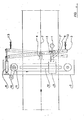
- Figure 1 is a side view of a type of apparatus for the continuous production of cement slabs reinforced by means of mesh obtained from plastics film, in particular fibrillated, using the method according to the present invention.
- the apparatus is mounted on a frame 14 formed from two parallel longitudinal members on which there slide a series of elements 15, the upper surface of which, shaped in accordance with the profile of the slabs to be obtained (flat or corrugated), comprises a series of holes of about 3 mm diameter spaced apart by about 20 mm, to allow passage of the excess water contained in the slab under formation.
- the water is removed through the tubes 16 connected to the longitudinal members of the frame 14 which in their turn communicate with the elements 15.
- a suction system with vacuum pumps (not shown) is connected to the tubes 16.
- the tubes 16 are connected to separated zones of the longitudinal members so as to be able to obtain zones of different degrees of vacuum at the slab under formation.
- the elements 15 are moved by two chains which are driven b) the wheels 17 and are deviated about the wheels 18.
- a cloth or felt band 19 acting as a filter rests on the elements 15 and advances rigidly with them in its upper part where the slab formation takes place. In its lower part, the cloth or felt band is deviated over rollers 22, 23, 24 and 28, and is washed by one or more sprayers 20, the operation of which can be aided by a beater 21.
- the cloth or felt band is also provided with guide and tensioning devices.
- the pump 25 removes the water which collects on the base of the tank 26.
- the cement mix is contained in a tank 1 containing a stirrer.
- Said cement mix is constituted mainly by a mixture of cement and water in which the water can vary from 30% to 60% and preferably from 35% to 45% by weight with respect to the cement.
- Said cement mix can also contain inert fillers such as sand, pigments, fibrous materials, pumice and fly ash to the extent of between 10% and 60% and preferably between 25X and 40% by weight, and additives such as flocculating, dispersing, accelerating and other agents.
- the cement mix is withdrawn from the tank 1 by the positive- displacement pumps 2, 3 and 4, which feed the spray units 5, 6 and 7 at constant throughput. Compressed air is fed through the line 31 to the guns which spray the cement mix on to the mesh.
- the mesh packaged into reels, is fed by the feeders 8, 9 and 10, which also keep said mesh under slight tension.
- the mesh is fed at a speed of between 0.5 and 18 m/minute and preferably between 4 and 10 m/minute.
- said mesh is constituted preferably by a fibrillated plastics film which can be of polyolefin, polyamide or other type.
- the mesh is preferably obtained from fibrillated polypropylene film.
- the mesh is guided on the cloth or felt by means of the devices 11, 12 and 13, which are in the form of smooth idle rollers. If the apparatus is equipped for producing slabs of corrugated profile, the devices 11, 12 and 13 would be constituted by a series of profiled rollers which accompany the mesh over the profiled contour of the elements 15.
- the mesh fed by the feader 8 After the mesh fed by the feader 8 has passed beyond the roller 11, it is impregnated with the cement-mix sprayed by the device 5. The mix completely penetrates between the mesh apertures in order to give complete impregnation by virtue of the spray pressure and its degree of atomisation.
- Figure 1 shows three mesh inoregnation stations corresponding to the spray units 5, 6 and 7 respectively.
- the number of these stations can vary from one to more than three according to the thickness of the mesh used. the type of structure, the number of component elementary layers and the thickness of the slab to be obtained.
- the proportion by weight of mesh to cement is kept between 1% and 6X and preferably between 3% and 5X.
- a smoothing device for example in the form of steel scraper blades, smoothing rollers or other means which exert a slight pressure on the sprayed mix to remove slight irregularities in the surface layer.
- each spray unit In order to make the layer of mix more uniform and to increase the rate of advancement of the slab under formation, several guns can be mounted on each spray unit.
- the suction system enables excess water to be extracted from the slab.
- the degree of vacuum can be independently adjusted in each suction zone.
- the degree of applied vacuum increases in the direction of advancement of the manufactured product.
- the purpose of the compression device 27 is to compact the slab, so reducing its porosity, and to smooth its surface in order to improve its appearance.
- the slab leaves the cloth or felt at the deviation wheel 28, is then trimmed longitudinally and transversely by the devices 29 and 30, and is fed to the curing cycle as in the case of fibre-cement slabs.
- the support function of the elements 15 can also be performed by a continuous felt band driven and deviated by rollers, and dried by suction boxes.
- a mandrel about which the impregnated mesh is wrapped for pipe formation.
- Figure 2 shows a plan view of a preferred embodiment of the device for uniformly distributing the cement mix over the mesh.
- the spray gun 1 is fed at constant throughput by a positive- displacement gun (not shown) and is rigid with the slide block 2 which can slide along the guide 3 with a to-and-fro movement as indicated by the arrows.
- the guide 3 is hinged to the support 4, which is rigid with the frame 5.
- the piston 6 can move the guide 3 into two positions (the position shown on the drawing by full lines and the position shown on the drawing by dashed lines respectively) which are symmetrical about the axis of the slab under formation, which advances in an underlying horizontal plane.
- the rod 7' is hinged to the slide block 2 and can slide in the tube 8 rigid with the carriage 9.
- the carriage 9 runs on the guide 10 driven by the chain 11, which is driven by the geared mc or 12.
- the carriage 9 is connected to one branch of the chain for its outward path of travel and to the other branch of the chain for its return path of travel respectively.
- the device for engaging and releasing the carriage 9 with and from the two branches of the chain is not shown.
- the spray gun 1 thus moves ti nsversely to the slab under formation with a to-and-fro movement while the slab advances horizontally in an underlying plane parallel to that in which the gun moves.
- the inclined guide 3 enables the gun to undergo a movement, of which the compon p nt parallel to the axis of advancement of the slab is of the same velocity as the slab itself.
- the piston 6 moves the guide 3 simultaneously with the reversal of movement of the carriage 9.
- the pattern of the sprayed material is in the form of several parallel bands perpendicular to the axis of advancement of the slab, to provide very regular impregnation of the mesh.
- the described device enables the paths of the jets delivered by the guns to be orientated at angles of other than 90° to the axis of advancement of the slab.
- the device of Figure 2 enables the movement of the various guns to be easily synchronised.
- a continuous production run was carried out on cement slabs reinforced with mesh obtained from fibrillated polypropylene film, using the apparatus shown in Figure 1 provided with four impregnation stations comprising the device shown in Figure 2.
- the cement mix had the following composition:
- Each of the four meshes consisted of 12 layers of poly ropylene film, of which 8 had their fibres orientated longitudinally and four had their fibres orientated transversely.
- Each mesh had a length of 65 cm and a weight of 60 g/m 2 .
- Each of the four meshes was fed at a rate of 4.5 m/minute, and the cement mix was fed at a throughput of 12 kg/minute for each impregnation station.
- the slab was compressed by a free steel roller of diameter 300 mm pressing on the slab with a force of about 3 kg/cm.
- the slabs were trimmed to a length of 200 cm and width of 60 cm, and were then cured in a moist environment at ambient temperature. Their thickness was 6.5 mm.
- the finished slabs had a propylene material content of 2.9% of the cement by weight.
- this polypropylene was distributed in the following manner: 1.93% in the longitudinal direction and 0.97% in the transverse direction.
- test pieces were cut from the finished slabs for testing breakage under longitudinal bending conditions, together with 10 test pieces for testing breakage under transverse bending conditions. Said test pieces had the following dimensions: length 175 nm, width 70 mm, thickness 6.5 mm.
- test pieces were tested by means of a Dillon Inc. tester (Van Nuys - California) Model M - Serial No. 868, the scale being calibrated 0-300 lbs, the test pieces being placed on two supports spaced apart by 150 mm and then loaded at their centre. The following results were obtained:
Landscapes
- Engineering & Computer Science (AREA)
- Chemical & Material Sciences (AREA)
- Ceramic Engineering (AREA)
- Manufacturing & Machinery (AREA)
- Mechanical Engineering (AREA)
- Materials Engineering (AREA)
- Structural Engineering (AREA)
- Organic Chemistry (AREA)
- Manufacturing Of Tubular Articles Or Embedded Moulded Articles (AREA)
- Preparation Of Clay, And Manufacture Of Mixtures Containing Clay Or Cement (AREA)
- Curing Cements, Concrete, And Artificial Stone (AREA)
- Producing Shaped Articles From Materials (AREA)
Abstract
Description
- This invention relates to a method and apparatus for the continuous production of manufactured cement products reinforced by means of mesh obtained from fibrillated plastics film.
- More particularly, the invention relates to a method and relative apparatus for the continuous production of products manufactured from cement mixes and reinforced by means of mesh obtained from plastics film, in which the mesh is incorporated into the mix by spraying said mix on to the mesh, which is made to continuously advance by moving along a horizontal plane rigid with a cloth or felt support, said cement mix being sprayed on to the continuously advancing mesh such that it becomes distributed uniformly over the mesh.
- The term "cement mix" or more simply the term "cement" indicates in the present description a mix consisting exclusively or mainly of one or more binders such as cement, lime and pozzolan, white gypsum binder and the like, with water.
- The term "plastics film mesh" or more simply "mesh" indicates in the present description any mesh obtained by treating continuous film, and in particular the mesh obtained by fibrillation for example as described in Italian patent application No. 9504A/77.
- The method and apparatus according to the present invention produce reinforced manufactured cement products such as flat or corrugated slabs, panels, tubes etc., which advantagely replace analogous manufactured asbestos cement products.
- In this respect, asbestos has the serious drawback of possessing toxicity characteristics, because of which it constitutes a danger to the health both of those workers who extract the material, and of users who are required to cut or saw manufactured cement products containing asbestos fibres.
- To obviate this drawback, manufactured cement products have been proposed in which the asbestos fibres are replaced by fibres obtained from fibrillated plastics film. However, the methods proposed up to the present time have the drawback of resulting in products which are either too costly or of unsatisfactory quality.
- For example, in British Patent No. 1,130,612 it is proposed to incorporate into the cement up to 2% of fibres having a length not exceeding 7.5 cm produced by stretching and fibrillating plastics film, particularly polypropylene, but the thin slabs obtained from mixtures containing such fibres are unsatisfactory for most applications.
- Italian patent application No. 9504A/77 describes the preparation of manufactured cement products reinforced by means of a mesh constituted by a fibrillated plastics film. However, this description offers no teaching regarding the method for obtaining the manufactured product, of which only a few samples are produced on a laboratory scale by methods which resemble manual methods and are in all cases discontinuous, so that the problem of transferring this principle to industrial production remains completely open.
- In this respect, in incorporating one or more mesh structures constituted by fibrillated plastics film into the cement it is difficult to obtain homogeneous distribution of the cement in the mesh, with the result that air bubbles form and portions of the reinforcing structures remain unimpregnated, especially where the manufacturing process is carried out at a speed which is of industrial interest. One attempt to solve this problem is described in Italian patent application No. 23761A/79 which claims a method and device for continuously manufacturing cement-based products with incorporated synthetic polymer mesh structures as reinforcement. The method consists of the following operations: continuously depositing a layer of cement mix on a horizontally moving band, continuously depositing the mesh structure on said layer, depositing a layer of cement mix on said mesh structure, compacting by vibration and finally compressing the assembly.
- This method has given rise to considerable drawbacks in its practical implementation.
- Firstly, the complexity of the operations and apparatus are such that problems arise in the form of interruptions and the need for frequent maintenance, which make the method too costly and the finished product commercially uncompetitive. Furthermore, the manufactured product obtained by the described method and device does not possess uniform mechanical characteristics, in that for example as a result of stressing by the application devices the mesh deforms so that it becomes thicker in certain zones and thinner in other zo:es. Again, the system provided for distributing the cement mix does not enable uniform penetration into the mesh interior to be obtained. For these reasons, the manufactured product obtained does not have the quality and price characteristics required by the market, so that said method has found no industrial application.
- All these drawbacks of the known art are obviated by the use of the method end apparatus according to the present invention.
- The method and apparatus for the continuous production of manufactured cement products reinforced by means of mesh obtained from fibrillated plastics film according to the invention are characterised in that the cement mix is applied to the mesh by spraying under pressure, the mesh bring made to advance with a continuous horizontal movement rigid with a suitable support means.
- the method and apparatus according to the present invention are further characterised in that the gun for spraying the cement mix undergoes movement in a plane parallel to and higher than the plane in which the mesh advances, said movement having a component perpendicular to the mesh axis and a component in the same direction as the mesh axis, this component having the same speed as the mesh itself. By operating in this manner, a product is obtained with uniform mechanical characteristics in that uniform distribution of the cement mix is ensured. The cement mix penetrates into the mesh without leaving empty spaces, and the mesh is uniformly distributed even if it consists of several layers. Moreover, highly concentrated cement mixes close to their final density can be used, and this characteristic together with the possibility of using several layers of superposed mesh for each impregnation station leads to the advantage of being able to operate with a reduced number of spraying stations.
- Finally, there is the advantage that the apparatus is simple and requires only modest maintenance.
- These and further advantages and characteristics of the method and apparatus according to the present invention will be apparent from the description and figures given hereinafter which relate to preferred methods of implementing the present invention, and are given by way of non-limiting example.
- Figure 1 is a side view of a type of apparatus for the continuous production of cement slabs reinforced by means of mesh obtained from plastics film, in particular fibrillated, using the method according to the present invention.
- The apparatus is mounted on a frame 14 formed from two parallel longitudinal members on which there slide a series of elements 15, the upper surface of which, shaped in accordance with the profile of the slabs to be obtained (flat or corrugated), comprises a series of holes of about 3 mm diameter spaced apart by about 20 mm, to allow passage of the excess water contained in the slab under formation. The water is removed through the tubes 16 connected to the longitudinal members of the frame 14 which in their turn communicate with the elements 15. A suction system with vacuum pumps (not shown) is connected to the tubes 16. The tubes 16 are connected to separated zones of the longitudinal members so as to be able to obtain zones of different degrees of vacuum at the slab under formation.
- The elements 15 are moved by two chains which are driven b) the
wheels 17 and are deviated about the wheels 18. - A cloth or felt
band 19 acting as a filter rests on the elements 15 and advances rigidly with them in its upper part where the slab formation takes place. In its lower part, the cloth or felt band is deviated overrollers more sprayers 20, the operation of which can be aided by abeater 21. The cloth or felt band is also provided with guide and tensioning devices. - The
pump 25 removes the water which collects on the base of thetank 26. - The feed systems for the cement mix and mesh are shown diagrammatically in the upper part of Figure 1.
- The cement mix is contained in a
tank 1 containing a stirrer. - Said cement mix is constituted mainly by a mixture of cement and water in which the water can vary from 30% to 60% and preferably from 35% to 45% by weight with respect to the cement. Said cement mix can also contain inert fillers such as sand, pigments, fibrous materials, pumice and fly ash to the extent of between 10% and 60% and preferably between 25X and 40% by weight, and additives such as flocculating, dispersing, accelerating and other agents.
- The cement mix is withdrawn from the
tank 1 by the positive-displacement pumps spray units 5, 6 and 7 at constant throughput. Compressed air is fed through theline 31 to the guns which spray the cement mix on to the mesh. - The mesh, packaged into reels, is fed by the
feeders - As stated, said mesh is constituted preferably by a fibrillated plastics film which can be of polyolefin, polyamide or other type. However, the mesh is preferably obtained from fibrillated polypropylene film.
- The mesh is guided on the cloth or felt by means of the
devices 11, 12 and 13, which are in the form of smooth idle rollers. If the apparatus is equipped for producing slabs of corrugated profile, thedevices 11, 12 and 13 would be constituted by a series of profiled rollers which accompany the mesh over the profiled contour of the elements 15. - After the mesh fed by the
feader 8 has passed beyond the roller 11, it is impregnated with the cement-mix sprayed by the device 5. The mix completely penetrates between the mesh apertures in order to give complete impregnation by virtue of the spray pressure and its degree of atomisation. - Figure 1 shows three mesh inoregnation stations corresponding to the
spray units 5, 6 and 7 respectively. However, the number of these stations can vary from one to more than three according to the thickness of the mesh used. the type of structure, the number of component elementary layers and the thickness of the slab to be obtained. - The proportion by weight of mesh to cement is kept between 1% and 6X and preferably between 3% and 5X.
- When using meshes consisting of several elementary layers or which are particularly difficult to impregnate, it is possible to adjust the distance of the roller 11 from the cloth or felt so as to keep the mesh slightly raised from the cloth or felt during impregnation. The degree of impregnation can be influenced in this manner.
- Downstream of the impregnation stage it is possible to install a smoothing device for example in the form of steel scraper blades, smoothing rollers or other means which exert a slight pressure on the sprayed mix to remove slight irregularities in the surface layer.
- Analogous operations are repeated on the meshes fed by the
feeders 9 and 10, to attain the final slab thickness. - In order to make the layer of mix more uniform and to increase the rate of advancement of the slab under formation, several guns can be mounted on each spray unit.
- The suction system enables excess water to be extracted from the slab. The degree of vacuum can be independently adjusted in each suction zone. Preferably, the degree of applied vacuum increases in the direction of advancement of the manufactured product.
- The purpose of the
compression device 27 is to compact the slab, so reducing its porosity, and to smooth its surface in order to improve its appearance. - The slab leaves the cloth or felt at the
deviation wheel 28, is then trimmed longitudinally and transversely by thedevices - It is apparent that numerous rodifications can be made to the described apparatus for implementing the method for forming manufactured cement products reinforced with plastics film mesh without leaving the scope of the present invention. For example, the support function of the elements 15 can also be performed by a continuous felt band driven and deviated by rollers, and dried by suction boxes. Again, if pipes are to be produced instead of slabs, it is necessary only to install downstream of the impregnation system a mandrel about which the impregnated mesh is wrapped for pipe formation.
- Figure 2 shows a plan view of a preferred embodiment of the device for uniformly distributing the cement mix over the mesh.
- The
spray gun 1 is fed at constant throughput by a positive- displacement gun (not shown) and is rigid with theslide block 2 which can slide along theguide 3 with a to-and-fro movement as indicated by the arrows. - The
guide 3 is hinged to the support 4, which is rigid with the frame 5. - The piston 6 can move the
guide 3 into two positions (the position shown on the drawing by full lines and the position shown on the drawing by dashed lines respectively) which are symmetrical about the axis of the slab under formation, which advances in an underlying horizontal plane. - The rod 7' is hinged to the
slide block 2 and can slide in thetube 8 rigid with the carriage 9. - The carriage 9 runs on the
guide 10 driven by the chain 11, which is driven by the geared mc or 12. The carriage 9 is connected to one branch of the chain for its outward path of travel and to the other branch of the chain for its return path of travel respectively. The device for engaging and releasing the carriage 9 with and from the two branches of the chain is not shown. Thespray gun 1 thus moves ti nsversely to the slab under formation with a to-and-fro movement while the slab advances horizontally in an underlying plane parallel to that in which the gun moves. - The
inclined guide 3 enables the gun to undergo a movement, of which the componpnt parallel to the axis of advancement of the slab is of the same velocity as the slab itself. - The piston 6 moves the
guide 3 simultaneously with the reversal of movement of the carriage 9. - The result of the described movements is that the pattern of the sprayed material is in the form of several parallel bands perpendicular to the axis of advancement of the slab, to provide very regular impregnation of the mesh.
- By variously setting the adjustment screws 13, the described device enables the paths of the jets delivered by the guns to be orientated at angles of other than 90° to the axis of advancement of the slab.
- Furthermore, if several impregnation stations are used, the device of Figure 2 enables the movement of the various guns to be easily synchronised.
- A non-limiting example is given hereinafter of the method and operation of the apparatus according to the present invention.
- A continuous production run was carried out on cement slabs reinforced with mesh obtained from fibrillated polypropylene film, using the apparatus shown in Figure 1 provided with four impregnation stations comprising the device shown in Figure 2.
- The cement mix had the following composition:
- - Cement 60% by weight of total
- - Water 42X
- - Sand 16%
- Each of the four meshes consisted of 12 layers of poly ropylene film, of which 8 had their fibres orientated longitudinally and four had their fibres orientated transversely.
- Each mesh had a length of 65 cm and a weight of 60 g/m2.
- Each of the four meshes was fed at a rate of 4.5 m/minute, and the cement mix was fed at a throughput of 12 kg/minute for each impregnation station.
- The excess water was removed from the slabs under formation by suction which in the final portion reached a vacuum level of 400 mm Hg.
- The slab was compressed by a free steel roller of diameter 300 mm pressing on the slab with a force of about 3 kg/cm.
- The slabs were trimmed to a length of 200 cm and width of 60 cm, and were then cured in a moist environment at ambient temperature. Their thickness was 6.5 mm. The finished slabs had a propylene material content of 2.9% of the cement by weight.
- On the aforesaid basis, this polypropylene was distributed in the following manner: 1.93% in the longitudinal direction and 0.97% in the transverse direction.
- 10 test pieces were cut from the finished slabs for testing breakage under longitudinal bending conditions, together with 10 test pieces for testing breakage under transverse bending conditions. Said test pieces had the following dimensions: length 175 nm, width 70 mm, thickness 6.5 mm.
- The test pieces were tested by means of a Dillon Inc. tester (Van Nuys - California) Model M - Serial No. 868, the scale being calibrated 0-300 lbs, the test pieces being placed on two supports spaced apart by 150 mm and then loaded at their centre. The following results were obtained:
- - breaking stress under longitudinal bending conditions: mean breaking stress = 306 kg/cm2;
standard deviation 16.86; - - breaking stress under transverse bending conditions: mean breaking stress = 170 kg/cm2;
standard deviation 4.5.
Claims (11)
Priority Applications (1)
| Application Number | Priority Date | Filing Date | Title |
|---|---|---|---|
| AT85100972T ATE64333T1 (en) | 1984-02-10 | 1985-01-31 | METHOD AND APPARATUS FOR THE CONTINUOUS PRODUCTION OF REINFORCED CEMENT PRODUCTS. |
Applications Claiming Priority (2)
| Application Number | Priority Date | Filing Date | Title |
|---|---|---|---|
| IT1955284 | 1984-02-10 | ||
| IT8419552A IT1209498B (en) | 1984-02-10 | 1984-02-10 | PROCESS AND EQUIPMENT FOR THE CONTINUOUS PRODUCTION OF REINFORCED CONCRETE MANUFACTURES. |
Publications (2)
| Publication Number | Publication Date |
|---|---|
| EP0152016A1 true EP0152016A1 (en) | 1985-08-21 |
| EP0152016B1 EP0152016B1 (en) | 1991-06-12 |
Family
ID=11158988
Family Applications (1)
| Application Number | Title | Priority Date | Filing Date |
|---|---|---|---|
| EP85100972A Expired - Lifetime EP0152016B1 (en) | 1984-02-10 | 1985-01-31 | Method and apparatus for the continuous production of reinforced manufactured cement products |
Country Status (4)
| Country | Link |
|---|---|
| EP (1) | EP0152016B1 (en) |
| AT (1) | ATE64333T1 (en) |
| DE (1) | DE3583152D1 (en) |
| IT (1) | IT1209498B (en) |
Cited By (4)
| Publication number | Priority date | Publication date | Assignee | Title |
|---|---|---|---|---|
| EP0192208A3 (en) * | 1985-02-15 | 1988-12-14 | Moplefan S.P.A. | Device for the continuous production of manufactured articles reinforced with hydraulic binders mixes and the corresponding process |
| EP0351730A1 (en) * | 1988-07-18 | 1990-01-24 | FIBRONIT S.r.l. | Method for producing building sheets containing cement, inert materials and additives, and reinforced with plastics mesh |
| EP0382181A3 (en) * | 1989-02-08 | 1991-11-06 | FIBRONIT S.r.l. | Concrete tubing reinforced with glass fibres and plastic material nets |
| WO1991012215A3 (en) * | 1990-02-12 | 1991-12-26 | Monk Construction Ltd | Ferrocement composition, method of forming objects therefrom and apparatus for use in such a method |
Citations (4)
| Publication number | Priority date | Publication date | Assignee | Title |
|---|---|---|---|---|
| FR2356610A1 (en) * | 1976-07-01 | 1978-01-27 | Univ Surrey | IMPROVEMENTS IN THE MANUFACTURING OF OBJECTS CONSTITUTED BY A REINFORCING ELEMENT AND BY A MASS HARDENED IN WATER |
| GB2003422A (en) * | 1977-08-30 | 1979-03-14 | Stamicarbon | Hardened objects of plastic net and water-hardenable binding agent |
| EP0003245A1 (en) * | 1977-12-30 | 1979-08-08 | Stamicarbon B.V. | Process for the manufacture of articles of water-hardening material |
| WO1981000375A1 (en) * | 1979-08-09 | 1981-02-19 | Tarmac Ind Holdings Ltd | Method and apparatus for the production of composite sheet material and a sheet material produced thereby |
-
1984
- 1984-02-10 IT IT8419552A patent/IT1209498B/en active
-
1985
- 1985-01-31 AT AT85100972T patent/ATE64333T1/en not_active IP Right Cessation
- 1985-01-31 DE DE8585100972T patent/DE3583152D1/en not_active Expired - Fee Related
- 1985-01-31 EP EP85100972A patent/EP0152016B1/en not_active Expired - Lifetime
Patent Citations (4)
| Publication number | Priority date | Publication date | Assignee | Title |
|---|---|---|---|---|
| FR2356610A1 (en) * | 1976-07-01 | 1978-01-27 | Univ Surrey | IMPROVEMENTS IN THE MANUFACTURING OF OBJECTS CONSTITUTED BY A REINFORCING ELEMENT AND BY A MASS HARDENED IN WATER |
| GB2003422A (en) * | 1977-08-30 | 1979-03-14 | Stamicarbon | Hardened objects of plastic net and water-hardenable binding agent |
| EP0003245A1 (en) * | 1977-12-30 | 1979-08-08 | Stamicarbon B.V. | Process for the manufacture of articles of water-hardening material |
| WO1981000375A1 (en) * | 1979-08-09 | 1981-02-19 | Tarmac Ind Holdings Ltd | Method and apparatus for the production of composite sheet material and a sheet material produced thereby |
Cited By (5)
| Publication number | Priority date | Publication date | Assignee | Title |
|---|---|---|---|---|
| EP0192208A3 (en) * | 1985-02-15 | 1988-12-14 | Moplefan S.P.A. | Device for the continuous production of manufactured articles reinforced with hydraulic binders mixes and the corresponding process |
| EP0351730A1 (en) * | 1988-07-18 | 1990-01-24 | FIBRONIT S.r.l. | Method for producing building sheets containing cement, inert materials and additives, and reinforced with plastics mesh |
| EP0382181A3 (en) * | 1989-02-08 | 1991-11-06 | FIBRONIT S.r.l. | Concrete tubing reinforced with glass fibres and plastic material nets |
| WO1991012215A3 (en) * | 1990-02-12 | 1991-12-26 | Monk Construction Ltd | Ferrocement composition, method of forming objects therefrom and apparatus for use in such a method |
| US5358751A (en) * | 1990-02-12 | 1994-10-25 | Hallgarth Construction Limited | Ferrocement lining units, methods of making them and methods of lining a water course with them |
Also Published As
| Publication number | Publication date |
|---|---|
| EP0152016B1 (en) | 1991-06-12 |
| DE3583152D1 (en) | 1991-07-18 |
| ATE64333T1 (en) | 1991-06-15 |
| IT8419552A0 (en) | 1984-02-10 |
| IT1209498B (en) | 1989-08-30 |
Similar Documents
| Publication | Publication Date | Title |
|---|---|---|
| US4450128A (en) | Glass fiber-reinforced cement plates | |
| US4344804A (en) | Process and apparatus for the manufacture of fiber-reinforced hydraulically bound articles such as cementitious articles | |
| EP0021362A1 (en) | Process and device for the manufacture of reinforced concrete slabs | |
| EP0192208B1 (en) | Device for the continuous production of manufactured articles reinforced with hydraulic binders mixes and the corresponding process | |
| RU1801091C (en) | Method and device for manufacturing articles from fiber-reinforced plastic | |
| US5814255A (en) | Process and device for the continuous production of fiber-reinforced molded bodies from hydraulically setting materials | |
| US4194946A (en) | Process for continuously preparing fiber reinforced cement | |
| US3931098A (en) | Method for producing webs, panels or sandwich elements of foam plastics reinforced with rovings | |
| DE2417558A1 (en) | METHOD AND DEVICES FOR THE PRODUCTION OF PANELS FROM GLASS FIBER REINFORCED CEMENT-LIKE MATERIAL | |
| GB2068820A (en) | Non-planar glass fibre reinforced cement articles | |
| EP0152016B1 (en) | Method and apparatus for the continuous production of reinforced manufactured cement products | |
| NO148331B (en) | PROCEDURE FOR THE MANUFACTURING OF ARTICLES CONSISTING OF HYDRAULIC BONDED MATERIALS, AND THE PROCEDURE FOR CARRYING OUT THE PROCEDURE | |
| DE3325643C2 (en) | Building board and method and device for their manufacture | |
| JPH0698614B2 (en) | Method for continuously producing shaped body of fiber-reinforced hydraulic mass | |
| DE2103931A1 (en) | Plant for the continuous manufacture of molded bodies, in particular plates, made of plaster of paris | |
| CA2112326C (en) | Fiber product and method and apparatus for production thereof | |
| DE3448348C2 (en) | Continuous fibre reinforced cement slab mfr | |
| EP1100662B1 (en) | Manufacture of building board | |
| JPS6032562B2 (en) | Manufacturing method and device for glass fiber reinforced cement board | |
| RU2100190C1 (en) | Method and production line for manufacturing reinforced construction material | |
| GB2041816A (en) | Continuous Production of Reinforced Sheet Material | |
| RU2037402C1 (en) | Constructional product continuous molding apparatus | |
| JPS6014684B2 (en) | Manufacturing method of glass fiber reinforced cement plate | |
| JPH04261809A (en) | Apparatus for preparing preliminary molded product of sheet-like thermosetting synthetic resin molding material | |
| EP0382181A2 (en) | Concrete tubing reinforced with glass fibres and plastic material nets |
Legal Events
| Date | Code | Title | Description |
|---|---|---|---|
| PUAI | Public reference made under article 153(3) epc to a published international application that has entered the european phase |
Free format text: ORIGINAL CODE: 0009012 |
|
| AK | Designated contracting states |
Designated state(s): AT BE CH DE FR GB LI LU NL SE |
|
| 17P | Request for examination filed |
Effective date: 19850927 |
|
| 17Q | First examination report despatched |
Effective date: 19890210 |
|
| RAP1 | Party data changed (applicant data changed or rights of an application transferred) |
Owner name: C.I.F.I. COMPAGNIA ITALIANA FINANZIARIA INDUSTRIAL |
|
| RAP3 | Party data changed (applicant data changed or rights of an application transferred) |
Owner name: C.I.F.I. COMPAGNIA ITALIANA FINANZIARIA INDUSTRIAL |
|
| GRAA | (expected) grant |
Free format text: ORIGINAL CODE: 0009210 |
|
| RAP1 | Party data changed (applicant data changed or rights of an application transferred) |
Owner name: S.I.D.I.-SOCIETE INTERNATIONALE DE DEVELOPPEMENTS |
|
| AK | Designated contracting states |
Kind code of ref document: B1 Designated state(s): AT BE CH DE FR GB LI LU NL SE |
|
| REF | Corresponds to: |
Ref document number: 64333 Country of ref document: AT Date of ref document: 19910615 Kind code of ref document: T |
|
| ET | Fr: translation filed | ||
| REF | Corresponds to: |
Ref document number: 3583152 Country of ref document: DE Date of ref document: 19910718 |
|
| PLBE | No opposition filed within time limit |
Free format text: ORIGINAL CODE: 0009261 |
|
| STAA | Information on the status of an ep patent application or granted ep patent |
Free format text: STATUS: NO OPPOSITION FILED WITHIN TIME LIMIT |
|
| 26N | No opposition filed | ||
| EPTA | Lu: last paid annual fee | ||
| EAL | Se: european patent in force in sweden |
Ref document number: 85100972.0 |
|
| PGFP | Annual fee paid to national office [announced via postgrant information from national office to epo] |
Ref country code: FR Payment date: 19960105 Year of fee payment: 12 |
|
| PGFP | Annual fee paid to national office [announced via postgrant information from national office to epo] |
Ref country code: GB Payment date: 19960111 Year of fee payment: 12 |
|
| PGFP | Annual fee paid to national office [announced via postgrant information from national office to epo] |
Ref country code: SE Payment date: 19960117 Year of fee payment: 12 |
|
| PGFP | Annual fee paid to national office [announced via postgrant information from national office to epo] |
Ref country code: CH Payment date: 19960119 Year of fee payment: 12 |
|
| PGFP | Annual fee paid to national office [announced via postgrant information from national office to epo] |
Ref country code: AT Payment date: 19960130 Year of fee payment: 12 |
|
| PGFP | Annual fee paid to national office [announced via postgrant information from national office to epo] |
Ref country code: NL Payment date: 19960131 Year of fee payment: 12 |
|
| PGFP | Annual fee paid to national office [announced via postgrant information from national office to epo] |
Ref country code: LU Payment date: 19960201 Year of fee payment: 12 |
|
| PGFP | Annual fee paid to national office [announced via postgrant information from national office to epo] |
Ref country code: DE Payment date: 19960227 Year of fee payment: 12 |
|
| PGFP | Annual fee paid to national office [announced via postgrant information from national office to epo] |
Ref country code: BE Payment date: 19960312 Year of fee payment: 12 |
|
| PG25 | Lapsed in a contracting state [announced via postgrant information from national office to epo] |
Ref country code: LU Free format text: LAPSE BECAUSE OF NON-PAYMENT OF DUE FEES Effective date: 19970131 Ref country code: LI Effective date: 19970131 Ref country code: GB Effective date: 19970131 Ref country code: CH Effective date: 19970131 Ref country code: BE Effective date: 19970131 Ref country code: AT Effective date: 19970131 |
|
| PG25 | Lapsed in a contracting state [announced via postgrant information from national office to epo] |
Ref country code: SE Effective date: 19970201 |
|
| BERE | Be: lapsed |
Owner name: SOC. INTERNATIONALE DE DEVELOPPEMENTS INDUSTRIELS Effective date: 19970131 |
|
| PG25 | Lapsed in a contracting state [announced via postgrant information from national office to epo] |
Ref country code: NL Effective date: 19970801 |
|
| REG | Reference to a national code |
Ref country code: CH Ref legal event code: PL |
|
| GBPC | Gb: european patent ceased through non-payment of renewal fee |
Effective date: 19970131 |
|
| PG25 | Lapsed in a contracting state [announced via postgrant information from national office to epo] |
Ref country code: FR Effective date: 19970930 |
|
| NLV4 | Nl: lapsed or anulled due to non-payment of the annual fee |
Effective date: 19970801 |
|
| PG25 | Lapsed in a contracting state [announced via postgrant information from national office to epo] |
Ref country code: DE Effective date: 19971001 |
|
| EUG | Se: european patent has lapsed |
Ref document number: 85100972.0 |
|
| REG | Reference to a national code |
Ref country code: FR Ref legal event code: ST |