EP0151663A1 - Float switch - Google Patents
Float switch Download PDFInfo
- Publication number
- EP0151663A1 EP0151663A1 EP84101487A EP84101487A EP0151663A1 EP 0151663 A1 EP0151663 A1 EP 0151663A1 EP 84101487 A EP84101487 A EP 84101487A EP 84101487 A EP84101487 A EP 84101487A EP 0151663 A1 EP0151663 A1 EP 0151663A1
- Authority
- EP
- European Patent Office
- Prior art keywords
- float switch
- switch according
- opening
- piston
- housing
- Prior art date
- Legal status (The legal status is an assumption and is not a legal conclusion. Google has not performed a legal analysis and makes no representation as to the accuracy of the status listed.)
- Withdrawn
Links
- 238000007789 sealing Methods 0.000 claims abstract description 9
- 239000012530 fluid Substances 0.000 claims abstract description 6
- 239000012811 non-conductive material Substances 0.000 claims abstract description 3
- QSHDDOUJBYECFT-UHFFFAOYSA-N mercury Chemical compound [Hg] QSHDDOUJBYECFT-UHFFFAOYSA-N 0.000 claims description 4
- 229910052753 mercury Inorganic materials 0.000 claims description 4
- 239000011521 glass Substances 0.000 claims description 2
- 239000004020 conductor Substances 0.000 claims 1
- 238000003466 welding Methods 0.000 claims 1
- 239000007788 liquid Substances 0.000 description 3
- 230000009347 mechanical transmission Effects 0.000 description 3
- 230000001771 impaired effect Effects 0.000 description 2
- 239000004743 Polypropylene Substances 0.000 description 1
- 239000004793 Polystyrene Substances 0.000 description 1
- 238000011109 contamination Methods 0.000 description 1
- 230000007797 corrosion Effects 0.000 description 1
- 238000005260 corrosion Methods 0.000 description 1
- 230000000694 effects Effects 0.000 description 1
- 239000012535 impurity Substances 0.000 description 1
- -1 polypropylene Polymers 0.000 description 1
- 229920001155 polypropylene Polymers 0.000 description 1
- 229920002223 polystyrene Polymers 0.000 description 1
Images
Classifications
-
- H—ELECTRICITY
- H01—ELECTRIC ELEMENTS
- H01H—ELECTRIC SWITCHES; RELAYS; SELECTORS; EMERGENCY PROTECTIVE DEVICES
- H01H35/00—Switches operated by change of a physical condition
- H01H35/18—Switches operated by change of liquid level or of liquid density, e.g. float switch
- H01H35/186—Switches operated by change of liquid level or of liquid density, e.g. float switch making use of a cable suspended floater containing an inclination sensing switch
Definitions
- the float switch 1 consists of a housing 2 in which a switching element 47 is arranged which, depending on the position of the float switch 1 on a power cable 5, can establish a current-conducting connection or an interruption of this connection.
Landscapes
- Switches Operated By Changes In Physical Conditions (AREA)
Abstract
Description
Die Erfindung betrifft einen Schwimmerschalter zur Ein- und Abschaltung elektrischer Einrichtungen wie Antriebsmotoren von Pumpen od. dgl.The invention relates to a float switch for switching on and off electrical devices such as drive motors of pumps or the like.
Schwimmerschalter sind bekannt, um in Abhängigkeit von dem Niveau einer Flüssigkeit bestimmte Antriebe schalten zu können. Sie bestehen im Regelfall aus einem Schwimmer, der mittels mechanischer Übertragungseinrichtungen auf einen Schaltkontakt einwirken kann. Bei diesen Schwimmerschaltern besteht der Nachteil, daß die mechanischen Übertragungseinrichtungen durch Verschmutzung oder Korrosion störanfällig sind, so daß im Laufe der Zeit die Schaltfunktion beeinträchtigt werden kann. Darüber hinaus erfordern die mechanischen Übertragungseinrichtungen eine gewisse räumliche Ausdehnung die oft als störend empfunden wird.Float switches are known in order to be able to switch certain drives depending on the level of a liquid. As a rule, they consist of a float that can act on a switch contact by means of mechanical transmission devices. The disadvantage of these float switches is that the mechanical transmission devices are susceptible to faults due to contamination or corrosion, so that the switching function can be impaired over time. In addition, the mechanical transmission devices require a certain spatial expansion, which is often perceived as disturbing.
Die Aufgabe der Erfindung besteht darin, einen Schwimmerschalter zu schaffen, der kompakt ausgebildet ist und nur geringe Abmessungen aufweist und dessen Funktion durch äußere Einwirkungen von Flüssigkeit oder in Flüssigkeiten enthaltenen Verunreinigungen nicht beeinträchtigt werden kann.The object of the invention is to provide a float switch which is of compact design and has only small dimensions and whose function cannot be impaired by external effects of liquid or impurities contained in liquids.
Erfindungsgemäß erfolgt die Lösung der Aufgabe durch ein wasserdicht als Schwimmkörper ausgebildetes Gehäuse mit einer Durchbrechung, durch das mittels eines Dichtelements flüssigkeitsdicht abgedichtet ein Stromkabel in das Gehäuse eingeführt ist, dessen stromleitende Adern endabschnittsseitig mit jeweils einem Kontaktglied verbunden sind, die voneinander distanziert an dem einen Endabschnitt eines an einem Schwinghebel schwenkbar gelagerten hohlen Kolbens aus elektrisch nicht leitfähigen Werkstoff in den Hohlraum des Kolbens hineinragend befestigt sind, in dem sich ein den Hohlraum teilweise ausfüllendes elektrisch leitendes Fluid befindet.According to the invention, the object is achieved by a water-tight housing designed as a floating body with an opening, through which a power cable is inserted in a liquid-tight manner by means of a sealing element, the current-conducting wires of which are connected at the end section side to a contact element, which are connected to one another at a distance from one end section of a hollow piston, which is pivotably mounted on a rocker arm and is made of electrically non-conductive material and projects into the cavity of the piston, in which there is an electrically conductive fluid that partially fills the cavity.
Weitere Merkmale der Erfindung werden in den Unteransprüchen beschrieben und nachstehend am Beispiel des in den Zeichnungen dargestellten erfindungsgemäßen Schwimmerschalters näher erläutert. Es zeigt
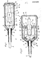
- Fig. 1 einen Schwimmerschalter in der Seitenansicht im Schnitt
- Fig. 2 den Schwimmerschalter nach Fig. 1 in der Draufsicht im Schnitt
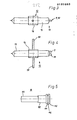
- Fig. 3 einen Schwinghebel mit Kolben in einer und 4 Seitenansicht und Draufsicht
- Fig. 5 ein als Lippklampe ausgebildetes Dichtelement in der Seitenansicht
- Fig. 1 shows a float switch in side view in section
- Fig. 2 shows the float switch according to Fig. 1 in plan view in section
- Fig. 3 shows a rocker arm with piston in one and 4 side and top views
- 5 shows a sealing element designed as a lip cleat in a side view
Der Schwimmerschalter 1 besteht aus einem Gehäuse 2, in dem ein Schaltglied 47 angeordnet ist, das je nach Lage des Schwimmerschalters 1 an einem Stromkabel 5 eine stromleitende Verbindung oder aber eine Unterbrechung dieser Verbindung herstellen kann.The
Das Gehäuse 2 besteht aus einer Außenschale 23 und einer Innenschale 22. Die Außenschale 23 kann z. B. aus Polypropylen bestehen und weist einen Grundkörper 37 und einen Deckel 38 auf. An dem einen Endabschnitt des Grundkörpers 37 ist ein buchsenförmiger Abschnitt 25 angeformt, in dem eine Durchbrechung 3 ausgebildet ist. An dem anderen Endabschnitt des Grundkörpers 37 ist ein umlaufender Steg 40 ausgebildet, an dem ein an dem Deckel 38 ausgebildeter Steg 41 anliegt. Die Stege 40, 41 können miteinander verklebt oder aber verschweißt sein.The
In der Außenschale 23 befindet sich die Innenschale 22, die aus zwei Halbschalen 26, 27 besteht. Die Halbschalen 26, 27 können z. B. aus Polystyrol od. dgl. ausgebildet sein und werden zur Herstellung der einstückigen Innenschale 22 im Bereich der aneinanderstoßenden Flächen miteinander verklebt. An den schmalseitigen Seitenflächen 28, 29 der Halbschalen 26, 27 ist jeweils ein Steg 30, 31 mit einer Ausnehmung 32 so ausgebildet, daß beim zusammenkleben der Halbschalen 26, 27 zur Innenschale 22 an den Stegen 30, 31 jeweils eine Lagerbuchse 18, 19 ausgebildet ist (Fig. 1 und 2).In the
In den Lagerbuchsen 18, 19 sind die Zapfen 15, 14 eines Schwinghebels 12 gelagert, der zum Schaltglied 47 gehört. Der Schwinghebel 12 besteht aus einer Buchse 16, an der außenseitig die Zapfen 14, 15 angeordnet sind. Durch die Buchse 16 ist ein als Glaskolben ausgebildeter Kolben 13 geführt, der als Hohlkörper ausgebildet ist (Fig. 3 und 4). In dem Kolben 13 befindet sich ein dessen Hohlraum nicht ganz ausfüllendes Fluid wie vorzugsweise Quecksilber. Bei einer vertikalen Lageveränderung des Schwimmerschalters 1 fließt das Quecksilber in den Kolben 13, wodurch dieser von einer Lage in die andere schwenken kann, wie es in Fig. 1 durch Strichlinien angedeutet ist.The
An dem einen Endabschnitt 11 des Kolbens 13 sind Kontaktglieder 9, 10 angeordnet, die in den Kolben 13 hineinragen. Jedes Kontaktglied 9, 10 ist mit einer stromleitenden Ader 7, 6 des Stromkabels 5 verbunden, das in das Gehäuse 2 eingeführt ist. Die Kontaktglieder 9, 10 sind voneinander distanziert angeordnet.At one
Eine elektrisch leitende Verbindung zwischen den Kontaktgliedern 9, 10 ist daher nur dann möglich, wenn bei entsprechender Lage des Kolbens 13 das Quecksilber die Kontaktglieder 9, 10 abdeckt.An electrically conductive connection between the
Um bei den einzelnen Schaltvorgängen des als Kippschalter ausgebildeten Schaltglieds 47 eine Beschädigung der stromleitenden Adern 6, 7 zu verhindern, ist jeweils eine Ader 6, 7 lose als Schleife 20, 21 um jeweils einen Zapfen 15, 14 geführt und in einer Durchbrechung 35 gehalten, die an einem an der Innenwand der Innenschale 22 beidseitig der Durchbrechung 24 ausgebildeten Steg 34 befindlich ist.In order to prevent damage to the current-conducting
Im Bereich der Durchbrechung 24 ist die Innenschale 22 in die Nut 46 eines als Lippklampe 5 ausgebildeten Dichtelements 3 eingeführt. Die Nut 46 ist durch zwei Flanschstege 44, 45 gebildet, die an der Dichtmuffe 42 der Lippklampe ausgebildet sind (Fig. 5). Die Dichtmuffe 42 wird dadurch in dem zwischen der Innenwandung des buchsenförmigen Abschnitts 25 und dem Stromkabel 5 gebildeten Hohlraum verpreßt, daß der Deckel 38 der Außenschale 23 bei Verbindung mit dem Grundkörper 37 die Innenschale 22 zur Durchbrechung 3 hin verschiebt.In the area of the
Claims (15)
Priority Applications (1)
| Application Number | Priority Date | Filing Date | Title |
|---|---|---|---|
| EP84101487A EP0151663A1 (en) | 1984-02-14 | 1984-02-14 | Float switch |
Applications Claiming Priority (1)
| Application Number | Priority Date | Filing Date | Title |
|---|---|---|---|
| EP84101487A EP0151663A1 (en) | 1984-02-14 | 1984-02-14 | Float switch |
Publications (1)
| Publication Number | Publication Date |
|---|---|
| EP0151663A1 true EP0151663A1 (en) | 1985-08-21 |
Family
ID=8191770
Family Applications (1)
| Application Number | Title | Priority Date | Filing Date |
|---|---|---|---|
| EP84101487A Withdrawn EP0151663A1 (en) | 1984-02-14 | 1984-02-14 | Float switch |
Country Status (1)
| Country | Link |
|---|---|
| EP (1) | EP0151663A1 (en) |
Cited By (4)
| Publication number | Priority date | Publication date | Assignee | Title |
|---|---|---|---|---|
| EP0231782A1 (en) * | 1986-01-17 | 1987-08-12 | Günter Reichensperger | Float switch |
| US7501456B2 (en) | 2006-04-27 | 2009-03-10 | Compactgtl Plc | Process for preparing liquid hydrocarbons |
| CN102456506A (en) * | 2010-10-26 | 2012-05-16 | 司捷易兰姆布斯控制科技(苏州)有限公司 | Floating ball |
| CN105321767A (en) * | 2015-05-05 | 2016-02-10 | 司捷易兰姆布斯控制科技(苏州)有限公司 | High-temperature float switch system |
Citations (5)
| Publication number | Priority date | Publication date | Assignee | Title |
|---|---|---|---|---|
| US3045084A (en) * | 1959-09-22 | 1962-07-17 | Sperowitz Seymour | Float switch |
| DE1914694U (en) * | 1965-02-27 | 1965-04-29 | Anton Huber Appbau | CONTROL BULB. |
| US3393283A (en) * | 1966-03-29 | 1968-07-16 | Inreco Ab | Liquid level switch with a two-piece float body of flexible material with a two-piece rigid liner member |
| DE7021515U (en) * | 1969-06-17 | 1971-02-18 | Reichensperger Guenter | FLOAT SWITCH HOUSING. |
| DE7100584U (en) * | 1971-01-08 | 1971-04-15 | Jung & Co | Float switch |
-
1984
- 1984-02-14 EP EP84101487A patent/EP0151663A1/en not_active Withdrawn
Patent Citations (5)
| Publication number | Priority date | Publication date | Assignee | Title |
|---|---|---|---|---|
| US3045084A (en) * | 1959-09-22 | 1962-07-17 | Sperowitz Seymour | Float switch |
| DE1914694U (en) * | 1965-02-27 | 1965-04-29 | Anton Huber Appbau | CONTROL BULB. |
| US3393283A (en) * | 1966-03-29 | 1968-07-16 | Inreco Ab | Liquid level switch with a two-piece float body of flexible material with a two-piece rigid liner member |
| DE7021515U (en) * | 1969-06-17 | 1971-02-18 | Reichensperger Guenter | FLOAT SWITCH HOUSING. |
| DE7100584U (en) * | 1971-01-08 | 1971-04-15 | Jung & Co | Float switch |
Cited By (4)
| Publication number | Priority date | Publication date | Assignee | Title |
|---|---|---|---|---|
| EP0231782A1 (en) * | 1986-01-17 | 1987-08-12 | Günter Reichensperger | Float switch |
| US7501456B2 (en) | 2006-04-27 | 2009-03-10 | Compactgtl Plc | Process for preparing liquid hydrocarbons |
| CN102456506A (en) * | 2010-10-26 | 2012-05-16 | 司捷易兰姆布斯控制科技(苏州)有限公司 | Floating ball |
| CN105321767A (en) * | 2015-05-05 | 2016-02-10 | 司捷易兰姆布斯控制科技(苏州)有限公司 | High-temperature float switch system |
Similar Documents
| Publication | Publication Date | Title |
|---|---|---|
| DE102005029458B4 (en) | Actuating device for electromedical devices, in particular foot switches, and method for producing such an actuator | |
| DE3818499A1 (en) | ELECTRONIC SWITCHGEAR, IN PARTICULAR PROXIMITY SWITCH | |
| EP0122465A2 (en) | Electrical switch or key switch with two actuating large area rockers | |
| EP0753198B1 (en) | Switch assembly for a built-in switch with a float-mounted actuator cover | |
| DE4310157C2 (en) | Connecting device | |
| EP0151663A1 (en) | Float switch | |
| CH623680A5 (en) | Switching apparatus | |
| DE4338562C2 (en) | Electrical connector component with secured sealing | |
| DE19507010A1 (en) | Electrical immersion motor pump with float switch | |
| DE4018978A1 (en) | SLIDE SWITCH | |
| EP0962122A1 (en) | Control device, especially a temperature control device such as a room temperature control device | |
| DE8404017U1 (en) | Float switch | |
| DE4017674C2 (en) | Electrical switch | |
| EP1008159A1 (en) | Switch with lifting ramp | |
| DE112017007138T5 (en) | Sealing structure of an electronic device, electronic device provided with a sealing structure and manufacturing method of the electronic device | |
| EP0116667B1 (en) | Actuator | |
| DE3305855A1 (en) | Device for recording the filling level of a liquid | |
| DE3112511C2 (en) | ||
| DE3244424A1 (en) | FUSE CONNECTING DEVICE FOR ENCLOSED MEDIUM VOLTAGE SYSTEMS | |
| DE3932125C2 (en) | switch | |
| DE2900726A1 (en) | Flexible snap-action system for pendant switches - has plastics element on slide and snapping in recesses of formed element | |
| DE2709998C2 (en) | Liquid-tight plain bearings for shafts in small components | |
| DE1790274B2 (en) | ELECTRIC SWITCH WITH A HERMETICALLY LOCKED HOUSING | |
| DE8908892U1 (en) | Connection seal for an electric motor | |
| DE610377C (en) | Light connection box placed on edge |
Legal Events
| Date | Code | Title | Description |
|---|---|---|---|
| PUAI | Public reference made under article 153(3) epc to a published international application that has entered the european phase |
Free format text: ORIGINAL CODE: 0009012 |
|
| AK | Designated contracting states |
Designated state(s): DE FR GB NL |
|
| STAA | Information on the status of an ep patent application or granted ep patent |
Free format text: STATUS: THE APPLICATION IS DEEMED TO BE WITHDRAWN |
|
| 18D | Application deemed to be withdrawn |
Effective date: 19860422 |
|
| RIN1 | Information on inventor provided before grant (corrected) |
Inventor name: KNUEPPEL, JAN |