EP0151569B1 - Process and apparatus for obtaining silicon from fluosilicic acid - Google Patents
Process and apparatus for obtaining silicon from fluosilicic acid Download PDFInfo
- Publication number
- EP0151569B1 EP0151569B1 EP83903866A EP83903866A EP0151569B1 EP 0151569 B1 EP0151569 B1 EP 0151569B1 EP 83903866 A EP83903866 A EP 83903866A EP 83903866 A EP83903866 A EP 83903866A EP 0151569 B1 EP0151569 B1 EP 0151569B1
- Authority
- EP
- European Patent Office
- Prior art keywords
- reaction
- silicon
- reaction chamber
- sif
- reactor
- Prior art date
- Legal status (The legal status is an assumption and is not a legal conclusion. Google has not performed a legal analysis and makes no representation as to the accuracy of the status listed.)
- Expired
Links
- 229910052710 silicon Inorganic materials 0.000 title claims abstract description 82
- 239000010703 silicon Substances 0.000 title claims abstract description 82
- 238000000034 method Methods 0.000 title claims abstract description 58
- 230000008569 process Effects 0.000 title claims abstract description 40
- 239000002253 acid Substances 0.000 title description 19
- 238000006243 chemical reaction Methods 0.000 claims abstract description 110
- ABTOQLMXBSRXSM-UHFFFAOYSA-N silicon tetrafluoride Chemical compound F[Si](F)(F)F ABTOQLMXBSRXSM-UHFFFAOYSA-N 0.000 claims abstract description 80
- 238000000926 separation method Methods 0.000 claims abstract description 34
- 229910021422 solar-grade silicon Inorganic materials 0.000 claims abstract description 9
- PUZPDOWCWNUUKD-UHFFFAOYSA-M sodium fluoride Chemical compound [F-].[Na+] PUZPDOWCWNUUKD-UHFFFAOYSA-M 0.000 claims description 125
- 239000011734 sodium Substances 0.000 claims description 91
- XUIMIQQOPSSXEZ-UHFFFAOYSA-N Silicon Chemical compound [Si] XUIMIQQOPSSXEZ-UHFFFAOYSA-N 0.000 claims description 79
- 239000011775 sodium fluoride Substances 0.000 claims description 62
- 235000013024 sodium fluoride Nutrition 0.000 claims description 62
- 239000007795 chemical reaction product Substances 0.000 claims description 38
- DGAQECJNVWCQMB-PUAWFVPOSA-M Ilexoside XXIX Chemical compound C[C@@H]1CC[C@@]2(CC[C@@]3(C(=CC[C@H]4[C@]3(CC[C@@H]5[C@@]4(CC[C@@H](C5(C)C)OS(=O)(=O)[O-])C)C)[C@@H]2[C@]1(C)O)C)C(=O)O[C@H]6[C@@H]([C@H]([C@@H]([C@H](O6)CO)O)O)O.[Na+] DGAQECJNVWCQMB-PUAWFVPOSA-M 0.000 claims description 31
- 229910052708 sodium Inorganic materials 0.000 claims description 31
- 239000007788 liquid Substances 0.000 claims description 26
- 239000000155 melt Substances 0.000 claims description 15
- 230000008018 melting Effects 0.000 claims description 13
- 238000002844 melting Methods 0.000 claims description 12
- 239000007787 solid Substances 0.000 claims description 11
- OKTJSMMVPCPJKN-UHFFFAOYSA-N Carbon Chemical compound [C] OKTJSMMVPCPJKN-UHFFFAOYSA-N 0.000 claims description 8
- 239000010439 graphite Substances 0.000 claims description 8
- 229910002804 graphite Inorganic materials 0.000 claims description 8
- 230000002093 peripheral effect Effects 0.000 claims description 4
- 230000000717 retained effect Effects 0.000 claims description 3
- 229910004014 SiF4 Inorganic materials 0.000 abstract description 61
- 238000006722 reduction reaction Methods 0.000 abstract description 20
- 150000003839 salts Chemical class 0.000 abstract description 15
- 230000009467 reduction Effects 0.000 abstract description 11
- 238000007599 discharging Methods 0.000 abstract description 5
- 229910052783 alkali metal Inorganic materials 0.000 abstract 1
- 150000001340 alkali metals Chemical class 0.000 abstract 1
- 239000012535 impurity Substances 0.000 description 25
- 239000000047 product Substances 0.000 description 21
- 239000000376 reactant Substances 0.000 description 21
- 239000007789 gas Substances 0.000 description 17
- 238000002347 injection Methods 0.000 description 15
- 239000007924 injection Substances 0.000 description 15
- 238000004519 manufacturing process Methods 0.000 description 11
- 238000002848 electrochemical method Methods 0.000 description 10
- 229910004883 Na2SiF6 Inorganic materials 0.000 description 8
- 239000004065 semiconductor Substances 0.000 description 8
- 229910052742 iron Inorganic materials 0.000 description 7
- 238000001556 precipitation Methods 0.000 description 7
- 238000000746 purification Methods 0.000 description 7
- 239000000243 solution Substances 0.000 description 7
- 229910003638 H2SiF6 Inorganic materials 0.000 description 6
- VYPSYNLAJGMNEJ-UHFFFAOYSA-N Silicium dioxide Chemical compound O=[Si]=O VYPSYNLAJGMNEJ-UHFFFAOYSA-N 0.000 description 6
- 239000000463 material Substances 0.000 description 6
- 229910052759 nickel Inorganic materials 0.000 description 6
- 229910052698 phosphorus Inorganic materials 0.000 description 6
- ZEFWRWWINDLIIV-UHFFFAOYSA-N tetrafluorosilane;dihydrofluoride Chemical compound F.F.F[Si](F)(F)F ZEFWRWWINDLIIV-UHFFFAOYSA-N 0.000 description 6
- 229910052785 arsenic Inorganic materials 0.000 description 5
- 229910052796 boron Inorganic materials 0.000 description 5
- 229910052804 chromium Inorganic materials 0.000 description 5
- 238000010438 heat treatment Methods 0.000 description 5
- 229910052751 metal Inorganic materials 0.000 description 5
- 239000005046 Chlorosilane Substances 0.000 description 4
- KRHYYFGTRYWZRS-UHFFFAOYSA-N Fluorane Chemical compound F KRHYYFGTRYWZRS-UHFFFAOYSA-N 0.000 description 4
- KOPOQZFJUQMUML-UHFFFAOYSA-N chlorosilane Chemical class Cl[SiH3] KOPOQZFJUQMUML-UHFFFAOYSA-N 0.000 description 4
- 238000001816 cooling Methods 0.000 description 4
- 229910052802 copper Inorganic materials 0.000 description 4
- 239000010949 copper Substances 0.000 description 4
- 238000000354 decomposition reaction Methods 0.000 description 4
- 150000002222 fluorine compounds Chemical class 0.000 description 4
- 239000002184 metal Substances 0.000 description 4
- 239000000203 mixture Substances 0.000 description 4
- 239000000843 powder Substances 0.000 description 4
- 239000010936 titanium Substances 0.000 description 4
- XLYOFNOQVPJJNP-UHFFFAOYSA-N water Substances O XLYOFNOQVPJJNP-UHFFFAOYSA-N 0.000 description 4
- KRHYYFGTRYWZRS-UHFFFAOYSA-M Fluoride anion Chemical compound [F-] KRHYYFGTRYWZRS-UHFFFAOYSA-M 0.000 description 3
- UFHFLCQGNIYNRP-UHFFFAOYSA-N Hydrogen Chemical compound [H][H] UFHFLCQGNIYNRP-UHFFFAOYSA-N 0.000 description 3
- HEMHJVSKTPXQMS-UHFFFAOYSA-M Sodium hydroxide Chemical compound [OH-].[Na+] HEMHJVSKTPXQMS-UHFFFAOYSA-M 0.000 description 3
- 229910052782 aluminium Inorganic materials 0.000 description 3
- 230000004888 barrier function Effects 0.000 description 3
- 239000006227 byproduct Substances 0.000 description 3
- 239000003638 chemical reducing agent Substances 0.000 description 3
- 239000002019 doping agent Substances 0.000 description 3
- 229910052739 hydrogen Inorganic materials 0.000 description 3
- 239000001257 hydrogen Substances 0.000 description 3
- 229910052750 molybdenum Inorganic materials 0.000 description 3
- 239000012071 phase Substances 0.000 description 3
- 238000001637 plasma atomic emission spectroscopy Methods 0.000 description 3
- 230000001376 precipitating effect Effects 0.000 description 3
- 229910001220 stainless steel Inorganic materials 0.000 description 3
- 239000010935 stainless steel Substances 0.000 description 3
- 229910052719 titanium Inorganic materials 0.000 description 3
- 229910052720 vanadium Inorganic materials 0.000 description 3
- 239000002699 waste material Substances 0.000 description 3
- QGZKDVFQNNGYKY-UHFFFAOYSA-N Ammonia Chemical compound N QGZKDVFQNNGYKY-UHFFFAOYSA-N 0.000 description 2
- IJGRMHOSHXDMSA-UHFFFAOYSA-N Atomic nitrogen Chemical compound N#N IJGRMHOSHXDMSA-UHFFFAOYSA-N 0.000 description 2
- RYGMFSIKBFXOCR-UHFFFAOYSA-N Copper Chemical compound [Cu] RYGMFSIKBFXOCR-UHFFFAOYSA-N 0.000 description 2
- KCXVZYZYPLLWCC-UHFFFAOYSA-N EDTA Chemical compound OC(=O)CN(CC(O)=O)CCN(CC(O)=O)CC(O)=O KCXVZYZYPLLWCC-UHFFFAOYSA-N 0.000 description 2
- QAOWNCQODCNURD-UHFFFAOYSA-N Sulfuric acid Chemical compound OS(O)(=O)=O QAOWNCQODCNURD-UHFFFAOYSA-N 0.000 description 2
- RTAQQCXQSZGOHL-UHFFFAOYSA-N Titanium Chemical compound [Ti] RTAQQCXQSZGOHL-UHFFFAOYSA-N 0.000 description 2
- 230000009471 action Effects 0.000 description 2
- 238000004458 analytical method Methods 0.000 description 2
- 239000007864 aqueous solution Substances 0.000 description 2
- 230000008901 benefit Effects 0.000 description 2
- 230000015572 biosynthetic process Effects 0.000 description 2
- 229910052791 calcium Inorganic materials 0.000 description 2
- 150000001805 chlorine compounds Chemical class 0.000 description 2
- 239000008139 complexing agent Substances 0.000 description 2
- 230000003247 decreasing effect Effects 0.000 description 2
- 238000010586 diagram Methods 0.000 description 2
- 230000000694 effects Effects 0.000 description 2
- 238000005516 engineering process Methods 0.000 description 2
- 238000002474 experimental method Methods 0.000 description 2
- 238000001914 filtration Methods 0.000 description 2
- 239000012530 fluid Substances 0.000 description 2
- 229910000040 hydrogen fluoride Inorganic materials 0.000 description 2
- 238000009413 insulation Methods 0.000 description 2
- 238000002955 isolation Methods 0.000 description 2
- 238000002386 leaching Methods 0.000 description 2
- 229910052749 magnesium Inorganic materials 0.000 description 2
- 229910052748 manganese Inorganic materials 0.000 description 2
- 238000004949 mass spectrometry Methods 0.000 description 2
- 229910001512 metal fluoride Inorganic materials 0.000 description 2
- 239000002245 particle Substances 0.000 description 2
- 230000000737 periodic effect Effects 0.000 description 2
- 239000002686 phosphate fertilizer Substances 0.000 description 2
- 238000010944 pre-mature reactiony Methods 0.000 description 2
- 230000005855 radiation Effects 0.000 description 2
- 238000011160 research Methods 0.000 description 2
- 238000013341 scale-up Methods 0.000 description 2
- 239000000377 silicon dioxide Substances 0.000 description 2
- -1 silicon halides Chemical class 0.000 description 2
- 239000002210 silicon-based material Substances 0.000 description 2
- 238000007711 solidification Methods 0.000 description 2
- 230000008023 solidification Effects 0.000 description 2
- 239000007858 starting material Substances 0.000 description 2
- 238000003860 storage Methods 0.000 description 2
- 239000006228 supernatant Substances 0.000 description 2
- 238000005979 thermal decomposition reaction Methods 0.000 description 2
- 238000002207 thermal evaporation Methods 0.000 description 2
- 229910052723 transition metal Inorganic materials 0.000 description 2
- 229910021561 transition metal fluoride Inorganic materials 0.000 description 2
- 150000003624 transition metals Chemical class 0.000 description 2
- 239000012498 ultrapure water Substances 0.000 description 2
- ZOXJGFHDIHLPTG-UHFFFAOYSA-N Boron Chemical compound [B] ZOXJGFHDIHLPTG-UHFFFAOYSA-N 0.000 description 1
- 241000282461 Canis lupus Species 0.000 description 1
- 241000198620 Infundibulicybe gibba Species 0.000 description 1
- 229910020440 K2SiF6 Inorganic materials 0.000 description 1
- BPQQTUXANYXVAA-UHFFFAOYSA-N Orthosilicate Chemical compound [O-][Si]([O-])([O-])[O-] BPQQTUXANYXVAA-UHFFFAOYSA-N 0.000 description 1
- 229910004074 SiF6 Inorganic materials 0.000 description 1
- QAOWNCQODCNURD-UHFFFAOYSA-L Sulfate Chemical compound [O-]S([O-])(=O)=O QAOWNCQODCNURD-UHFFFAOYSA-L 0.000 description 1
- 229910052770 Uranium Inorganic materials 0.000 description 1
- 238000002441 X-ray diffraction Methods 0.000 description 1
- XAGFODPZIPBFFR-UHFFFAOYSA-N aluminium Chemical compound [Al] XAGFODPZIPBFFR-UHFFFAOYSA-N 0.000 description 1
- 229910021529 ammonia Inorganic materials 0.000 description 1
- 229910052787 antimony Inorganic materials 0.000 description 1
- 238000013459 approach Methods 0.000 description 1
- 230000005540 biological transmission Effects 0.000 description 1
- 230000005587 bubbling Effects 0.000 description 1
- 229910052799 carbon Inorganic materials 0.000 description 1
- 230000008859 change Effects 0.000 description 1
- 239000003795 chemical substances by application Substances 0.000 description 1
- 238000000975 co-precipitation Methods 0.000 description 1
- 239000011248 coating agent Substances 0.000 description 1
- 238000000576 coating method Methods 0.000 description 1
- 150000001875 compounds Chemical class 0.000 description 1
- 238000011109 contamination Methods 0.000 description 1
- 230000000779 depleting effect Effects 0.000 description 1
- 238000001514 detection method Methods 0.000 description 1
- 230000001627 detrimental effect Effects 0.000 description 1
- 238000011161 development Methods 0.000 description 1
- 238000009792 diffusion process Methods 0.000 description 1
- 230000003292 diminished effect Effects 0.000 description 1
- 239000012153 distilled water Substances 0.000 description 1
- 238000009826 distribution Methods 0.000 description 1
- 238000001035 drying Methods 0.000 description 1
- 230000005611 electricity Effects 0.000 description 1
- 230000002349 favourable effect Effects 0.000 description 1
- 239000003337 fertilizer Substances 0.000 description 1
- 150000004673 fluoride salts Chemical class 0.000 description 1
- 239000003517 fume Substances 0.000 description 1
- 230000006870 function Effects 0.000 description 1
- 229910052735 hafnium Inorganic materials 0.000 description 1
- 150000004820 halides Chemical class 0.000 description 1
- 230000006698 induction Effects 0.000 description 1
- 230000003993 interaction Effects 0.000 description 1
- 230000000155 isotopic effect Effects 0.000 description 1
- 229910052744 lithium Inorganic materials 0.000 description 1
- 238000011068 loading method Methods 0.000 description 1
- 230000007246 mechanism Effects 0.000 description 1
- 238000010309 melting process Methods 0.000 description 1
- 150000002739 metals Chemical class 0.000 description 1
- 230000005012 migration Effects 0.000 description 1
- 238000013508 migration Methods 0.000 description 1
- 229910052758 niobium Inorganic materials 0.000 description 1
- 229910052757 nitrogen Inorganic materials 0.000 description 1
- 239000003921 oil Substances 0.000 description 1
- 230000008520 organization Effects 0.000 description 1
- 238000005191 phase separation Methods 0.000 description 1
- 239000002244 precipitate Substances 0.000 description 1
- 230000035484 reaction time Effects 0.000 description 1
- 238000011946 reduction process Methods 0.000 description 1
- 150000004760 silicates Chemical class 0.000 description 1
- 239000002002 slurry Substances 0.000 description 1
- 159000000000 sodium salts Chemical class 0.000 description 1
- 239000007790 solid phase Substances 0.000 description 1
- 239000012265 solid product Substances 0.000 description 1
- 239000007921 spray Substances 0.000 description 1
- 238000005507 spraying Methods 0.000 description 1
- 239000000126 substance Substances 0.000 description 1
- 150000003467 sulfuric acid derivatives Chemical class 0.000 description 1
- 229910021653 sulphate ion Inorganic materials 0.000 description 1
- 239000010414 supernatant solution Substances 0.000 description 1
- 229910052715 tantalum Inorganic materials 0.000 description 1
- 238000012546 transfer Methods 0.000 description 1
- 229910001428 transition metal ion Inorganic materials 0.000 description 1
- 229910052721 tungsten Inorganic materials 0.000 description 1
- 238000009489 vacuum treatment Methods 0.000 description 1
- 238000009834 vaporization Methods 0.000 description 1
- 230000008016 vaporization Effects 0.000 description 1
- 238000010792 warming Methods 0.000 description 1
- 210000002268 wool Anatomy 0.000 description 1
- 229910052726 zirconium Inorganic materials 0.000 description 1
Images
Classifications
-
- B—PERFORMING OPERATIONS; TRANSPORTING
- B01—PHYSICAL OR CHEMICAL PROCESSES OR APPARATUS IN GENERAL
- B01J—CHEMICAL OR PHYSICAL PROCESSES, e.g. CATALYSIS OR COLLOID CHEMISTRY; THEIR RELEVANT APPARATUS
- B01J19/00—Chemical, physical or physico-chemical processes in general; Their relevant apparatus
- B01J19/26—Nozzle-type reactors, i.e. the distribution of the initial reactants within the reactor is effected by their introduction or injection through nozzles
-
- B—PERFORMING OPERATIONS; TRANSPORTING
- B01—PHYSICAL OR CHEMICAL PROCESSES OR APPARATUS IN GENERAL
- B01J—CHEMICAL OR PHYSICAL PROCESSES, e.g. CATALYSIS OR COLLOID CHEMISTRY; THEIR RELEVANT APPARATUS
- B01J4/00—Feed or outlet devices; Feed or outlet control devices
- B01J4/001—Feed or outlet devices as such, e.g. feeding tubes
-
- C—CHEMISTRY; METALLURGY
- C01—INORGANIC CHEMISTRY
- C01B—NON-METALLIC ELEMENTS; COMPOUNDS THEREOF; METALLOIDS OR COMPOUNDS THEREOF NOT COVERED BY SUBCLASS C01C
- C01B33/00—Silicon; Compounds thereof
- C01B33/02—Silicon
- C01B33/021—Preparation
- C01B33/027—Preparation by decomposition or reduction of gaseous or vaporised silicon compounds other than silica or silica-containing material
- C01B33/033—Preparation by decomposition or reduction of gaseous or vaporised silicon compounds other than silica or silica-containing material by reduction of silicon halides or halosilanes with a metal or a metallic alloy as the only reducing agents
-
- B—PERFORMING OPERATIONS; TRANSPORTING
- B01—PHYSICAL OR CHEMICAL PROCESSES OR APPARATUS IN GENERAL
- B01J—CHEMICAL OR PHYSICAL PROCESSES, e.g. CATALYSIS OR COLLOID CHEMISTRY; THEIR RELEVANT APPARATUS
- B01J2219/00—Chemical, physical or physico-chemical processes in general; Their relevant apparatus
- B01J2219/00049—Controlling or regulating processes
- B01J2219/00051—Controlling the temperature
- B01J2219/00074—Controlling the temperature by indirect heating or cooling employing heat exchange fluids
- B01J2219/00087—Controlling the temperature by indirect heating or cooling employing heat exchange fluids with heat exchange elements outside the reactor
- B01J2219/0009—Coils
-
- B—PERFORMING OPERATIONS; TRANSPORTING
- B01—PHYSICAL OR CHEMICAL PROCESSES OR APPARATUS IN GENERAL
- B01J—CHEMICAL OR PHYSICAL PROCESSES, e.g. CATALYSIS OR COLLOID CHEMISTRY; THEIR RELEVANT APPARATUS
- B01J2219/00—Chemical, physical or physico-chemical processes in general; Their relevant apparatus
- B01J2219/00049—Controlling or regulating processes
- B01J2219/00051—Controlling the temperature
- B01J2219/00132—Controlling the temperature using electric heating or cooling elements
- B01J2219/00135—Electric resistance heaters
-
- B—PERFORMING OPERATIONS; TRANSPORTING
- B01—PHYSICAL OR CHEMICAL PROCESSES OR APPARATUS IN GENERAL
- B01J—CHEMICAL OR PHYSICAL PROCESSES, e.g. CATALYSIS OR COLLOID CHEMISTRY; THEIR RELEVANT APPARATUS
- B01J2219/00—Chemical, physical or physico-chemical processes in general; Their relevant apparatus
- B01J2219/00049—Controlling or regulating processes
- B01J2219/00051—Controlling the temperature
- B01J2219/0015—Controlling the temperature by thermal insulation means
-
- B—PERFORMING OPERATIONS; TRANSPORTING
- B01—PHYSICAL OR CHEMICAL PROCESSES OR APPARATUS IN GENERAL
- B01J—CHEMICAL OR PHYSICAL PROCESSES, e.g. CATALYSIS OR COLLOID CHEMISTRY; THEIR RELEVANT APPARATUS
- B01J2219/00—Chemical, physical or physico-chemical processes in general; Their relevant apparatus
- B01J2219/00049—Controlling or regulating processes
- B01J2219/00162—Controlling or regulating processes controlling the pressure
-
- B—PERFORMING OPERATIONS; TRANSPORTING
- B01—PHYSICAL OR CHEMICAL PROCESSES OR APPARATUS IN GENERAL
- B01J—CHEMICAL OR PHYSICAL PROCESSES, e.g. CATALYSIS OR COLLOID CHEMISTRY; THEIR RELEVANT APPARATUS
- B01J2219/00—Chemical, physical or physico-chemical processes in general; Their relevant apparatus
- B01J2219/00049—Controlling or regulating processes
- B01J2219/00164—Controlling or regulating processes controlling the flow
-
- B—PERFORMING OPERATIONS; TRANSPORTING
- B01—PHYSICAL OR CHEMICAL PROCESSES OR APPARATUS IN GENERAL
- B01J—CHEMICAL OR PHYSICAL PROCESSES, e.g. CATALYSIS OR COLLOID CHEMISTRY; THEIR RELEVANT APPARATUS
- B01J2219/00—Chemical, physical or physico-chemical processes in general; Their relevant apparatus
- B01J2219/00049—Controlling or regulating processes
- B01J2219/00245—Avoiding undesirable reactions or side-effects
Definitions
- Silicon is, at present, the most important material in modern semiconductor technology and is finding increased use in solar cells for the photovoltaic generation of electricity.
- the process and apparatus is described primarily in the context of production of silicon for solar cell use. However, it is to be understood that both the process and apparatus used are generally useful in the production of silicon for whatever end use, as well as other transition metals such as Ti, Zr, Hf, V, Nb and Ta.
- the silicon fluoride is prepared from an aqueous solution of fluosilicic acid, a low cost waste by-product of the phosphate fertilizer industry by treatment with a metal fluoride which precipitates the corresponding fluosilicate.
- This salt is filtered, washed, dried and thermally decomposed to produce the corresponding silicon tetrafluoride and metal fluoride which can be recycled to the precipitation step.
- the silicon tetrafluoride is then reduced by a suitable reducing metal and the products of reactions are treated to extract the silicon.
- Each of the steps is described in detail using sodium as reducing agent, and sodium fluoride as precipitating fluoride.
- reaction product After the reaction product has been cooled at least to 200°C it is finely divided and is treated with water or heattreated with dilute 1:1 sulfuric acid. Hydrogen fluoride gas is liberated (which latter can then be made into hydrofluoric acid or a metallic fluoride) metallic sulphates are produced and the silicon separates out on the surface in amorphous form as shining metallic froth.
- silicon of the desired grade is obtained without the elaborate purification of commercial grade sodium or silicon tetrafluorude obtained from the fluosilicic acid (from the reaction shown above) provided the reduction reaction is carried out in such a way that it goes to completion, the proper environment is maintained during the reduction reaction and the product is properly isolated from contaminating atmosphere and container walls until the reaction is complete and solid silicon which is below reaction temperature is formed and separated.
- the isolation from the container may be carried out using a powdered substance so that the reaction product does not adhere and can be removed by a simple dumping process. The system is successful but generally is not needed in connection with the melt separation of the present process.
- the present invention is directed to the part of the process which deals with the manner of carrying out the separation of the products of reaction (Si and NaF) produced by the reaction between SiF 4 and Na.
- reaction products produced by the systems disclosed in the patents are in a form that is difficult to separate.
- separation techniques that tend to introduce impurities are distinctly disadvantageous.
- This report discloses a process for producing solar grade silicon by employing, as a primary source of silicon, fluosilicic acid which is obtained as a by-product in the production of fertilizers, converting said acid to sodium fluosilicate, decomposing said silicate to yield silicon tetrafluoride, reacting said fluoride with sodium so as to obtain a mixture of sodium fluoride and silicon and recovering the desired silicon from said mixture either in a melt separation procedure or by an acid leaching technique.
- the melt separation procedure comprises heating the reaction product to temperatures above the melting point of Si, so as to obtain a clean phase separation between the Si agglomerated at the bottom of the crucible and the NaF into an upper liquid layer.
- the present invention is specifically concerned with melt separation of the reaction products produced by reaction of Na and SiF 4 .
- the reaction is performed in a reaction chamber configured in such a manner that the reaction products (Si and NaF) are easily separated by melt separation and the NaF continuously removed.
- sodium fluosilicate Na 2 SiF 6 is precipitated from fluosilicic acid followed by thermal decomposition of the fluosilicate to silicon tetrafluoride SiF 4 .
- the SiF 4 is then reduced by Na, to obtain silicon which is separated from the mix by melt separation.
- the reduction reaction is carried out by jetting finely divided reactants into a reaction chamber at a rate and temperature which causes the reaction to take place far enough away from the injection or entry region so that there is no plugging at the entry area and thus, the reactants are freely introduced.
- the reaction is carried out inside a reaction chamber configured in such a manner that the resulting reaction products (Si and NaF) which are formed within the reaction chamber can be separated directly and the NaF continuously removed as a molten liquid by passing through one or more drainage channels (of suitable cross section) running downward along the lower peripheral reactor chamber side wall and along the reactor chamber bottom passing through one or more drainage ports for discharging NaF.
- a reaction chamber configured in such a manner that the resulting reaction products (Si and NaF) which are formed within the reaction chamber can be separated directly and the NaF continuously removed as a molten liquid by passing through one or more drainage channels (of suitable cross section) running downward along the lower peripheral reactor chamber side wall and along the reactor chamber bottom passing through one or more drainage ports for discharging NaF.
- the invention has for its principal object the provision of a process for obtaining silicon of sufficient purity to produce solar photovoltaic cells inexpensively enough to make their use practical.
- a further object of this invention is to provide a process by means of which silicon can be obtained which is substantially free of impurities starting with relatively inexpensive and impure fluosilicic acid.
- a still further object of this invention is to provide a process for producing Si wherein SiF 4 and a reductant, Na, are introduced into a reactor in finely divided form and at a rate and temperature that causes the reduction to take place at a location removed from the entry area so that the reaction products do not prevent introduction of either of the reactants into the reactor.
- Another object of the invention is to provide a process for producing solar grade Si by reaction of SiF 4 and a reductant in such a manner that Si is separated from the reaction products continuously and directly.
- Yet another object of the invention is to provide a reactor vessel for separating Si from the molten reaction products of a Si producing reaction.
- Still a further object of the invention is to provide process and apparatus for continuously separating Si in molten form from the molten reaction products.
- Another object of the invention is to provide process and apparatus for continuously separating Si in molten form from the molten reaction salt products by gravitationally discharging the molten salt products.
- a further object of the invention is to provide process and apparatus for continuously separating Si in solid form from the molten reaction salt products by gravitationally discharging the molten salt products.
- the process for producing low cost, high purity, solar grade silicon comprises reacting, in substantially stoechiometric quantities, liquid sodium introduced through a first inlet means at the top of a reaction chamber with gaseous silicon tetrafluoride introduced through a second inlet means surrounding said first inlet means, said reaction chamber being formed of graphite, and recovering the silicon reaction product by a melt separation technique; and this process is characterized in that the bottom portion of the reaction chamber has one or more drainage ports therethrough of a size between 2 and 3.5 millimeters in diameter and the reaction is carried out so that sodium fluoride is continuously removed as a molten liquid by passing through the drainage ports due to the low surface tension thereof as compared to that of silicon and the silicon, which may be under liquid or solid form, is retained in the reaction chamber, substantially free of sodium fluoride.
- the apparatus according to present invention is a reaction chamber for producing low cost, high purity, solar grade silicon by reaction of gaseous silicon tetrafluoride with liquid sodium in substantially stoechiometric quantities and recovering the silicon reaction product by a melt separation technique and comprising a top wall, provided with a first inlet means for introducing liquid sodium and a second inlet means, surrounding said first inlet means, for introducing gaseous silicon tetrafluoride and comprising a wall portion and a bottom portion, formed of graphite; and this reaction chamber is characterized in that said bottom portion has one or more drainage ports therethrough, of a size between 2 and 3.5 millimeters in diameter to allow passage of molten sodium fluoride but to prevent passage of molten silicon.
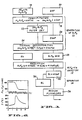
- a preferred embodiment of the process for production of pure silicon starting with inexpensive commercial grade fluosilicic acid is illustrated in the flow diagram of Figure 1.
- the overall process consists of three major operations which encompass a series of steps.
- the first major operation includes the step of precipitation of sodium fluosilicate from fluosilicic acid followed by generation of silicon tetrafluoride gas.
- the second major operation comprises the reduction of silicon tetrafluoride to silicon, by sodium and the third operation (brackets 14) involves the separation of silicon from the mixture of silicon and sodium fluoride.
- the preferred starting source of silicon is an aqueous solution of fluosilicic acid (H 2 SiF 6 ), a waste product of the phosphate fertilizer industry, that is inexpensive and available in large quantities.
- Fluorsilicic acid of commercial grade [23 weight percent (w%)] has also been used directly as received without purification or special treatment and is shown as the silicon source 16 in Figure 1.
- fluosilicic acid is obtained by treating silica, or silicates (natural or artificially made) with hydrogen fluoride.
- the SiF 6 - 2 is then precipitated in sodium fluosilicate Na 2 SiF 6 , by adding a sodium salt to the solution (step 18).
- salts such as NaF, NaOH, NaCI, or similar salts of the elements in Groups IA and IIA of the periodic table are all candidates.
- the major selection criteria are, low solubility of the corresponding fluosilicate, high solubility of impurities in the supernatant solution, high solubility of the precipitating fluoride salt, and non-hygroscopic character of the fluosilicate.
- the preferred fluosilicates in order of preference are Na 2 SiF 6 , K 2 SiF 6 and BaSiF s .
- the hydrogen of the fluosilicic acid is displaced by the sodium to form sodium fluosilicate, a highly stable, nonhygroscopic, white powder, and sodium fluoride which is recycled.
- the reaction is
- Sodium fluosilicate was precipitated by adding solid sodium fluoride directly to the as received commercial grade fluosilicic acid 18.
- the yield was a supernatant liquid containing mostly HF and some NaF and H 2 SiF 6 along with the sodium fluosilicate. HF is also given off 20).
- the supernatant fluid was removed and the sodium fluosilicate washed with cold distilled water to remove any remaining HF and H 2 SiF 6 . After filtering and drying in an oven at 200 degrees C, a minimum yield of 92% of pure sodium fluosilicate 22 (determined by x-ray diffraction) was obtained.
- the product sodium fluosilicate is a nonhygroscopic white powder that is very stable at room temperature and thus provides an excellent means for storing the silicon source before it is decomposed to silicon tetrafluoride.
- Precipitation under the just described conditions acts as a purification step, with most impurities in the original fluosilicic acid staying in solution. This effect is increased by adding suitable complexing agents to the fluosilicic acid solution previous to the precipitation.
- suitable complexing agents such as ammonia and organic agents such as EDTA (ethylenediaminetetraacetic acid) help to keep transition metal ions in solution during precipitation of the fluosilicate.
- the fluosilicate is thermally decomposed 24, thus, to give the solid sodium fluoride, which is recycled 26, and to generate the SiF 4 gas 28.
- the decomposition does not take place appreciably at temperatures below 400°C. Therefore, impurities which are volatile at this temperature can easily be removed by a vacuum treatment below this temperature.
- the decomposition of Na takes place at temperatures between about 500 and 700°C. Impurities left in the solid phase are typically transition metal fluorides such as Fe, Ni, Cu, etc., whose volatility at temperatures below 700°C is very low and therefore do not contaminate the SiF 4 gas.
- the gas thus produced can be fed directly to the reduction reactor or it can be stored for future use.
- SiF 4 gas prepared in this manner was determined by mass spectrometric analysis to be more pure than commercial grade SiF 4 , as shown in Table I. Ions formed from the sample gas were identified from the observed mass numbers, isotopic distribution and threshold appearance potentials. The detection limit was better than 0.005%. Positively identified gaseous impurities are listed in Table I; no metallic impurities were detected. Peaks corresponding to B compounds, such as BF 3 , were specially checked, but none were found.
- the kinetic behavior of the Na-SiF 4 reaction is complex because of the interplay of several factors, e.g., pressure of SiF 4 , vaporization of Na, local temperature, porosity of two solid products, and transport of SiF 4 and Na vapor through the product crust that forms on the liquid Na.
- reaction temperature 5 grams of Na were loaded in a Ni crucible (3 cm ID, 4 cm high) and heated in SiF 4 initially at about 10 5 Pa (1 atm) pressure.
- the SiF 4 /Na reaction became rapid at about 160°C+/-10°C and liberated a large amount of heat, as indicated by a sudden rise in reaction temperature.
- the pressure in the reactor typically decreased slightly until the temperature increased sharply, with an associated rapid decrease in SiF 4 pressure.
- the reaction lasts for several seconds only (until the Na is consumed).
- SiF 4 pressures below 0.3 105 Pa (0.3 atm) the reaction mass was observed to glow at a dull red heat.
- a characteristic flame was observed.
- the shortest reaction time (20 sec) and the highest temperatures (about 1400°C) were obtained when the initial pressure of SiF 4 was about 10 5 Pa (1 atm).
- complete consumption of Na was obtained for 10 5 Pa (1 atm) SIF4.
- scale-up of this reaction was attempted by loading larger amounts of Na, it was found that as the depth of the Na pool increased, the amount of Na remaining unreacted also increased.
- the product formed a crust on top of the Na surface, building a diffusion barrier for the reactants. As the barrier thickness increased, the reaction slowed and eventually stopped.
- the products are heated until a melt is formed and the NaF is drained off (36) leaving the Si 34.
- the melting and separation process is described in detail below in connection with the scaled up system.
- the silicon and sodium are removed and combined with water and a selected acid.
- the resultant silicon and water soluble sodium fluoride are then separated.
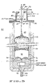
- Figure 3 which includes a reactant feed arrangement and a reaction product separation configuration in the central vertical section through the reactor. It is noted that the reactant feed arrangement is specifically designed to cause the reduction reaction to take place far enough away from the feed system (into the reactor) positively to prevent build up of reaction products at the entry and, thus, avoid any possibility of plugging of the entering reactants.
- the upper section 40 of the reactor system shown somewhat schematically in Fig. 3, constitutes a reactant (Na and SiF 4 ) dispenser and the lower section 42 is the reactor section where the reaction takes place.
- the reactant dispenser section 40 includes a stainless steel liquid sodium injection tube 44 vertically and centrally located in the top flange 46 of the reactor.
- the Na injection tube 44 is provided with a conventional stainless steel bellows valve 48 for controlling Na flow into the reactor section 42.
- the inner diameter of the Na injection tube 44 is selected to provide the desired Na jetting action, assure an appropriate Na stream ejection velocity and Na stream size.
- a SiF 4 feed head 50 is positioned concentrically around the entry portion of the Na ejection tube 44 with its ejection aperture 52 positioned to feed SiF 4 into the reactor concentrically around the Na stream 54.
- the SiF 4 is fed into the reactor at room temperature and its entry is controlled by a constant pressure valve 56 in order to keep pressure constant in the reactor at from about 0.5 . 105 to about 5 . 105 Pa (about 0.5 to about 5 atmospheres). That is, as SiF 4 is fed concentrically with the Na into the hot zone of the reactor, the SiF 4 -Na reaction takes place depleting SiF 4 .
- the depletion in turn activates the constant pressure valve 56, thus, feeding more SiF 4 into the reactor.
- the resultant gas flow keeps a relatively constant temperature at the injection region by its cooling action and by producing a jet that keeps hot particles of reaction products from reaching the nozzle end of Na feed tube 44. Keeping the reaction products away from the reactant entry area in this manner eliminates plugging of the injection apertures.
- This mode of operation increases the rate of Si production.
- a Na nozzle exit aperture of 0.127 mm (0.005 inch) and jetting Na above its reacting temperature of 150°C the reaction took place far enough away from the entry area to prevent plugging for injection temperatures up to about 50° C. No plugging occurs for reaction temperatures up to about 900°C.
- the reduction reaction takes place in the lower reactor section 42 of the reactor system.
- the reduction reaction is highly exothermic and therefore, temperature control is desirable to help prevent reaction products from moving up near the reactant injection area. Such control prevents reactants from plugging the injection nozzle and preventing reactant injection.
- the top reactant injection nozzle supporting flange 46 for the reactor 42 is cupped 58) or recessed (upwardly in the drawing) thermally to isolate the injection area from the hotter regions of the reactor 42. Further isolation from the hot reaction region is provided by inserting a disk like toroidal heat insulating baffle 60 between the reaction zone and the nozzle thus, effectively forming a semi-isolated nozzle entry chamber 62.
- the centrally located aperture 64 in the baffle 60 is of a size to let reactants from the nozzle enter the reaction zone, prevent the injected products from spraying the outer reactor walls and minimize heat transmission between the reaction area in the reactor 42 and the nozzle entry chamber 62.
- Additional temperature control is provided by oil cooled tubing 66 which extends around the cupped portion 58 of the nozzle supporting flange 46.
- oil cooled tubing 66 which extends around the cupped portion 58 of the nozzle supporting flange 46.
- the cooling coils 66 in cooperation with the reactant input temperatures, jet velocities and heat shielding baffle 60 maintain the reactant feed area below this temperature, premature reaction at the feed port and nozzle plugging is prevented.
- the SiF 4 is preferably injected at a temperature of between about -86° and 120°C and the liquid Na is jetted at a temperature of between about 98° and 130°C.
- reaction products NaF and Si
- the reaction products will be separated by a melt process at temperatures above the melting point of Si (1412°C) and preferably in the range between about 1450 and 1500°C. It is also contemplated that the separation and removal of the salt products of reaction will take place on a continuous basis.
- the physical structure and configuration of the reactor portion 42 of the system is designed to produce such results.
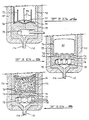
- the same reactor designed for melt separation of the reaction products (i.e., Si 90 and NaF 76) above the melting point of Si may also be utilized to separate NaF 76 from Si 86 (as illustrated in Fig. 6) at temperatures between below about 1412°C and above about the melting temperature of NaF (as illustrated in Figure 6).
- the reactor section 42 includes a generally cylindrical reaction product receiving and separating container 72.
- the container 72 is composed of high purity graphite and in order to perform the separation of reaction products, the lower portion of the container 72 is generally designed to be enclosed by at least one bottom portion 74 (as illustrated in Fig. 4) which is preferably (semi) toroidal in shape with a solid non-porous cylindrical molten NaF removing drainage port 77 in the center and thus, having the appearance of a common funnel.
- the drainage port 77 is shown closed by a movable drain plug 78.
- the chamber bottom may be configured (as illustrated in Fig.
- the Na and SiF 4 are jetted into the inner container 72 through the aperture 64 in the heat insulating baffle 60 and reaction starts to take place in the hot upper reaction zone 80.
- a pool 82 of reacted and partially reacted Na and SiF 4 form where the reaction goes to completion (pool described above).
- a hotter melt separation zone 84 is formed.
- the melt separation zone 84 is maintained at a much higher temperature (means of heating explained below) than the reaction products zone 82 above it and the reaction products effectively melt out.
- the reaction products Si and NaF
- the reaction products are liquids which are separable because the NaF will normally float on top of the Si.
- Liquid NaF which melts at about 993°C, is immiscible with Si and usually wets graphite in the presence of liquid Si.
- the NaF does not discharge well and for apertures appreciably greater than about 3.5 mm Si tends to enter and interfere with NaF discharge.
- the NaF is removed by extracting the movable closure plug 78 to allow the NaF to flow out of the reaction container drainage port(s) 77.
- the closure plug may be of different configuration depending on the configuration and number of drainage ports forming the bottom of the reaction chamber. The flow is adjusted so that the process is continuous.
- the flow of NaF out the drainage port(s) 77 is adjusted so that the reduction reaction is continuously taking place in the reaction zone 80 and reaction products continuously settle through the reaction product zone 82 and into the melt separation zone 84 with NaF continuously flowing out the drainage port(s) while Si is retained at the bottom of the reaction chamber.
- the container 72 at its lower portion be lined with suitable channels to facilitate NaF drainage.
- the lower reactor chamber side wall and reactor chamber bottom be constructed to have a plurality of connected drainage channels 73 (of suitable cross section, preferably about 2 to about 3.5 millimeters in effective cross-section) running downward along the lower peripheral reaction chamber side wall and along the reactor chamber bottom into one or more drainage ports 77 for discharging reaction salt products (i.e., NaF).
- the (semi) toroidal shape bottom 74 and the inner cylindrical reactor side wall meet to form a circular shaped edge trough 75 which is contemplated to facilitate the passage of NaF along the bend connecting the side wall and bottom channels.
- reactor chamber bottom is contemplated to have a surface of positive total curvature sufficient to displace the molten Si pool 90 bottom surface away from the (bend) edge trough 75 and further facilitate the passage of NaF along their channeled paths.
- the heating elements are covered with a silica felt insulation 100 (1.3 cm thick).
- the remaining NaF 76 (next to the Si 90 in the case at which the separation zone 84 is operated above about the melting point of silicon or next to the Si 86 (as illustrated in Fig. 6) in the case at which the separation zone 84 is operated below about the melting point of silicon) is easily removed by a conventional aqueous leaching process.
- the salt coating 76 is readily removed in 1.0 N acid solution.
- Fig. 1 The process sequence shown in Fig. 1 was selected because of the inherent simplicity of the steps and their independent and combined suitability for scale-up.
- Some purification occurs during precipitation (operation 1, Fig. 1) for Mg, Ca, Al, P, and As due to the high solubility of their fluosilicates and fluosalts.
- Some concentration takes place for Cr, Fe, and Ni, and this effect may be due to coprecipitation of these elements as fluorides since their fluosilicates are very soluble. From Table II, it is clear that most of the purification is accomplished as a result of the thermal decomposition in step 24 (Fig. 1).
- Most transition metal fluorides are in very stable condensed phases at the decomposition temperature (650°C) in step 24 (Fig.
- the impurities in Na can be divided roughly into three types according to their tendency to react with SiF 4 , as classified by the free energy of reaction.
- the first type of impurity includes aluminum and elements from the groups IA, IIA and IIIB.
- the free energy of reaction of SiF 4 with these impurities ranges from about -100 to -200 kcal/mole SiF 4 at room temperature and from about -50 to -100 kcal/mole SiF 4 at about 815°5C (1500°K). It is expected, therefore, that even when these impurities are present at the ppm level, they will react with the SiF 4 to form corresponding fluorides. Subsequently, the fluorides will be dissolved preferentially in the NaF phase.
- the second type impurity includes transition metals such as Mo, W, Fe, Co, Ni, and Cu, and the elements P, As, and Sb. These elements exhibit positive free energies of reaction in excess of 100 kcal/mole SiF 4 and are not expected to react with SiF 4 .
- the silicon resulting from the SiF 4 -Na reaction contains amounts of Fe, Ni, and Cr in proportion to the concentration of these elements in the Na feed.
- the mechanism by which these metals are transferred to the silicon has not yet been studied.
- the concentration of Fe, Cr, Ni, and also Ti can be decreased by a factor of about 10 4 to 10 6 for single-pass directional solidification or the Czochralski crystal-pulling procedures used presently for solar cell manufacture. At the resulting levels, these elements would not be detrimental to solar cell performance.
Landscapes
- Chemical & Material Sciences (AREA)
- Organic Chemistry (AREA)
- Chemical Kinetics & Catalysis (AREA)
- Inorganic Chemistry (AREA)
- Silicon Compounds (AREA)
Applications Claiming Priority (2)
| Application Number | Priority Date | Filing Date | Title |
|---|---|---|---|
| US453337 | 1982-12-27 | ||
| US06/453,337 US4584181A (en) | 1982-12-27 | 1982-12-27 | Process and apparatus for obtaining silicon from fluosilicic acid |
Publications (3)
| Publication Number | Publication Date |
|---|---|
| EP0151569A1 EP0151569A1 (en) | 1985-08-21 |
| EP0151569A4 EP0151569A4 (en) | 1986-07-10 |
| EP0151569B1 true EP0151569B1 (en) | 1989-07-19 |
Family
ID=23800171
Family Applications (1)
| Application Number | Title | Priority Date | Filing Date |
|---|---|---|---|
| EP83903866A Expired EP0151569B1 (en) | 1982-12-27 | 1983-11-07 | Process and apparatus for obtaining silicon from fluosilicic acid |
Country Status (12)
| Country | Link |
|---|---|
| US (1) | US4584181A (en, 2012) |
| EP (1) | EP0151569B1 (en, 2012) |
| CA (1) | CA1221816A (en, 2012) |
| CH (1) | CH661918A5 (en, 2012) |
| DE (1) | DE3390358T1 (en, 2012) |
| ES (1) | ES8602534A1 (en, 2012) |
| GB (1) | GB2142918B (en, 2012) |
| GR (1) | GR78764B (en, 2012) |
| IT (1) | IT1172395B (en, 2012) |
| NL (1) | NL8320373A (en, 2012) |
| PT (1) | PT77852B (en, 2012) |
| WO (1) | WO1984002514A1 (en, 2012) |
Families Citing this family (15)
| Publication number | Priority date | Publication date | Assignee | Title |
|---|---|---|---|---|
| EP0166481A3 (en) * | 1984-06-26 | 1988-11-23 | AGIP S.p.A. | Process for obtaining silicon or transition metals from their halides |
| FI72952C (fi) * | 1985-03-11 | 1987-08-10 | Kemira Oy | Foerfarande foer framstaellning av kisel. |
| US4655827A (en) * | 1985-07-24 | 1987-04-07 | Angel Sanjurjo | Process for the reduction of fluorides of silicon, titanium, zirconium or uranium |
| US5925443A (en) * | 1991-09-10 | 1999-07-20 | International Business Machines Corporation | Copper-based paste containing copper aluminate for microstructural and shrinkage control of copper-filled vias |
| RU2131843C1 (ru) * | 1998-03-30 | 1999-06-20 | Институт геохимии им.Виноградова А.П. СО РАН | Способ получения кремния высокой чистоты |
| EP1474361B1 (de) * | 2002-01-18 | 2006-08-02 | Wacker Chemie AG | Verfahren zur herstellung von organohalogensilanen aus amorphem silizium |
| JP5311930B2 (ja) * | 2007-08-29 | 2013-10-09 | 住友化学株式会社 | シリコンの製造方法 |
| EP2328846B1 (en) * | 2008-08-28 | 2014-03-19 | SRI International | Method and system for producing fluoride gas and fluorine-doped glass or ceramics |
| EP2373577B1 (en) * | 2008-12-17 | 2014-09-10 | MEMC Electronic Materials, Inc. | Processes and systems for producing silicon tetrafluoride from fluorosilicates in a fluidized bed reactor |
| US8609057B2 (en) | 2010-06-07 | 2013-12-17 | Sri International | Method for separation of components from a reaction mixture via a concentrated acid |
| US9101896B2 (en) | 2010-07-09 | 2015-08-11 | Sri International | High temperature decomposition of complex precursor salts in a molten salt |
| DE102010045260A1 (de) | 2010-09-14 | 2012-03-15 | Spawnt Private S.À.R.L. | Verfahren zur Herstellung von fluorierten Polysilanen |
| US8701444B2 (en) * | 2012-06-22 | 2014-04-22 | Owens-Brockway Glass Container Inc. | Plunger and parison mold assembly for a narrow-neck press-and-blow wine bottle |
| CN103395785B (zh) * | 2013-07-18 | 2014-12-31 | 贵州省产品质量监督检验院 | 一种钠还原氟硅酸钠制备多晶硅的方法 |
| RU2690070C1 (ru) * | 2018-07-04 | 2019-05-30 | Общество с ограниченной ответственностью "Научно-производственное предприятие "ТЕХНОПРИБОР" (ООО "НПП "ТЕХНОПРИБОР") | Устройство дозирования подщелачивающего реагента анализатора натрия |
Citations (11)
| Publication number | Priority date | Publication date | Assignee | Title |
|---|---|---|---|---|
| US3966460A (en) * | 1974-09-06 | 1976-06-29 | Amax Specialty Metal Corporation | Reduction of metal halides |
| US4102767A (en) * | 1977-04-14 | 1978-07-25 | Westinghouse Electric Corp. | Arc heater method for the production of single crystal silicon |
| US4102766A (en) * | 1977-04-14 | 1978-07-25 | Westinghouse Electric Corp. | Process for doping high purity silicon in an arc heater |
| US4102765A (en) * | 1977-01-06 | 1978-07-25 | Westinghouse Electric Corp. | Arc heater production of silicon involving alkali or alkaline-earth metals |
| US4162291A (en) * | 1977-10-12 | 1979-07-24 | Westinghouse Electric Corp. | Liquid silicon casting control mechanism |
| US4188368A (en) * | 1978-03-29 | 1980-02-12 | Nasa | Method of producing silicon |
| US4233338A (en) * | 1977-08-31 | 1980-11-11 | Produits Chimiques Ugine Kuhlmann | Processes for deposition of thin films of crystalline silicon on graphite |
| US4269620A (en) * | 1978-06-02 | 1981-05-26 | Kemanord Ab | Process for the preparation of silicon or ferrosilicon |
| US4272488A (en) * | 1977-05-25 | 1981-06-09 | John S. Pennish | Apparatus for producing and casting liquid silicon |
| US4366024A (en) * | 1979-01-26 | 1982-12-28 | Heliotronic Forschungs-Und Entwicklungsgesellschaft Fur Solarzellen-Grundstoffe Mbh | Process for making solar cell base material |
| US4388286A (en) * | 1982-01-27 | 1983-06-14 | Atlantic Richfield Company | Silicon purification |
Family Cites Families (19)
| Publication number | Priority date | Publication date | Assignee | Title |
|---|---|---|---|---|
| US524173A (en) * | 1894-08-07 | Variable-resistance medium for telephones | ||
| US1518872A (en) * | 1920-04-16 | 1924-12-09 | Pacz Aladar | Process of producing fluorides |
| US2172969A (en) * | 1936-09-28 | 1939-09-12 | Eringer Josef | Process for obtaining silicon from its compounds |
| US2828201A (en) * | 1950-10-13 | 1958-03-25 | Nat Res Corp | Method for producing titanium and zirconium |
| US2826491A (en) * | 1951-09-10 | 1958-03-11 | Nat Res Corp | Method of producing refractory metals |
| GB821817A (en) * | 1954-11-16 | 1959-10-14 | Peter Spence & Sons Ltd | Continuous process for the manufacture of titanium metal |
| US2840588A (en) * | 1956-03-22 | 1958-06-24 | Du Pont | Process for the preparation of difluorosilylene and the polymers thereof |
| US2816828A (en) * | 1956-06-20 | 1957-12-17 | Nat Res Corp | Method of producing refractory metals |
| US2909411A (en) * | 1957-01-15 | 1959-10-20 | Du Pont | Production of silicon |
| US3041145A (en) * | 1957-07-15 | 1962-06-26 | Robert S Aries | Production of pure silicon |
| US2941867A (en) * | 1957-10-14 | 1960-06-21 | Du Pont | Reduction of metal halides |
| US3012865A (en) * | 1957-11-25 | 1961-12-12 | Du Pont | Silicon purification process |
| US3847596A (en) * | 1968-02-28 | 1974-11-12 | Halomet Ag | Process of obtaining metals from metal halides |
| US4070444A (en) * | 1976-07-21 | 1978-01-24 | Motorola Inc. | Low cost, high volume silicon purification process |
| US4102764A (en) * | 1976-12-29 | 1978-07-25 | Westinghouse Electric Corp. | High purity silicon production by arc heater reduction of silicon intermediates |
| US4102985A (en) * | 1977-01-06 | 1978-07-25 | Westinghouse Electric Corp. | Arc heater production of silicon involving a hydrogen reduction |
| US4138509A (en) * | 1977-12-23 | 1979-02-06 | Motorola, Inc. | Silicon purification process |
| US4169129A (en) * | 1978-02-24 | 1979-09-25 | Nasa | Sodium storage and injection system |
| US4298587A (en) * | 1980-10-28 | 1981-11-03 | Atlantic Richfield Company | Silicon purification |
-
1982
- 1982-12-27 US US06/453,337 patent/US4584181A/en not_active Expired - Fee Related
-
1983
- 1983-11-07 CH CH3707/84A patent/CH661918A5/de not_active IP Right Cessation
- 1983-11-07 DE DE19833390358 patent/DE3390358T1/de not_active Withdrawn
- 1983-11-07 GB GB08417389A patent/GB2142918B/en not_active Expired
- 1983-11-07 EP EP83903866A patent/EP0151569B1/en not_active Expired
- 1983-11-07 NL NL8320373A patent/NL8320373A/nl unknown
- 1983-11-07 WO PCT/US1983/001738 patent/WO1984002514A1/en active IP Right Grant
- 1983-12-02 GR GR73144A patent/GR78764B/el unknown
- 1983-12-07 CA CA000442780A patent/CA1221816A/en not_active Expired
- 1983-12-19 PT PT77852A patent/PT77852B/pt not_active IP Right Cessation
- 1983-12-26 ES ES528413A patent/ES8602534A1/es not_active Expired
- 1983-12-27 IT IT49590/83A patent/IT1172395B/it active
Patent Citations (11)
| Publication number | Priority date | Publication date | Assignee | Title |
|---|---|---|---|---|
| US3966460A (en) * | 1974-09-06 | 1976-06-29 | Amax Specialty Metal Corporation | Reduction of metal halides |
| US4102765A (en) * | 1977-01-06 | 1978-07-25 | Westinghouse Electric Corp. | Arc heater production of silicon involving alkali or alkaline-earth metals |
| US4102767A (en) * | 1977-04-14 | 1978-07-25 | Westinghouse Electric Corp. | Arc heater method for the production of single crystal silicon |
| US4102766A (en) * | 1977-04-14 | 1978-07-25 | Westinghouse Electric Corp. | Process for doping high purity silicon in an arc heater |
| US4272488A (en) * | 1977-05-25 | 1981-06-09 | John S. Pennish | Apparatus for producing and casting liquid silicon |
| US4233338A (en) * | 1977-08-31 | 1980-11-11 | Produits Chimiques Ugine Kuhlmann | Processes for deposition of thin films of crystalline silicon on graphite |
| US4162291A (en) * | 1977-10-12 | 1979-07-24 | Westinghouse Electric Corp. | Liquid silicon casting control mechanism |
| US4188368A (en) * | 1978-03-29 | 1980-02-12 | Nasa | Method of producing silicon |
| US4269620A (en) * | 1978-06-02 | 1981-05-26 | Kemanord Ab | Process for the preparation of silicon or ferrosilicon |
| US4366024A (en) * | 1979-01-26 | 1982-12-28 | Heliotronic Forschungs-Und Entwicklungsgesellschaft Fur Solarzellen-Grundstoffe Mbh | Process for making solar cell base material |
| US4388286A (en) * | 1982-01-27 | 1983-06-14 | Atlantic Richfield Company | Silicon purification |
Also Published As
| Publication number | Publication date |
|---|---|
| DE3390358T1 (de) | 1985-01-24 |
| ES528413A0 (es) | 1985-11-16 |
| PT77852A (en) | 1984-01-01 |
| GB2142918A (en) | 1985-01-30 |
| EP0151569A4 (en) | 1986-07-10 |
| CH661918A5 (de) | 1987-08-31 |
| IT1172395B (it) | 1987-06-18 |
| PT77852B (en) | 1986-04-16 |
| NL8320373A (nl) | 1984-11-01 |
| GB8417389D0 (en) | 1984-08-08 |
| WO1984002514A1 (en) | 1984-07-05 |
| GB2142918B (en) | 1987-02-25 |
| EP0151569A1 (en) | 1985-08-21 |
| CA1221816A (en) | 1987-05-19 |
| ES8602534A1 (es) | 1985-11-16 |
| GR78764B (en, 2012) | 1984-10-02 |
| US4584181A (en) | 1986-04-22 |
Similar Documents
| Publication | Publication Date | Title |
|---|---|---|
| US4442082A (en) | Process for obtaining silicon from fluosilicic acid | |
| US4753783A (en) | Process and apparatus for obtaining silicon from fluosilicic acid | |
| EP0151569B1 (en) | Process and apparatus for obtaining silicon from fluosilicic acid | |
| US4529576A (en) | Process and apparatus for obtaining silicon from fluosilicic acid | |
| US4597948A (en) | Apparatus for obtaining silicon from fluosilicic acid | |
| US4748014A (en) | Process and apparatus for obtaining silicon from fluosilicic acid | |
| US4781565A (en) | Apparatus for obtaining silicon from fluosilicic acid | |
| US8974761B2 (en) | Methods for producing silane | |
| US9487406B2 (en) | Systems for producing silane | |
| US5110531A (en) | Process and apparatus for casting multiple silicon wafer articles | |
| EP0098297A1 (en) | Process and apparatus for obtaining silicon from fluosilicic acid | |
| JPS60500334A (ja) | 弗化珪素酸から珪素を製造する装置 | |
| EP2655247A1 (en) | Methods and systems for producing silane | |
| KR101151272B1 (ko) | 고순도 다결정 실리콘 제조장치 | |
| DE112009003720T5 (de) | Verfahren zur Herstellung von Silicium |
Legal Events
| Date | Code | Title | Description |
|---|---|---|---|
| PUAI | Public reference made under article 153(3) epc to a published international application that has entered the european phase |
Free format text: ORIGINAL CODE: 0009012 |
|
| 17P | Request for examination filed |
Effective date: 19841220 |
|
| AK | Designated contracting states |
Designated state(s): BE FR |
|
| A4 | Supplementary search report drawn up and despatched |
Effective date: 19860710 |
|
| 17Q | First examination report despatched |
Effective date: 19870827 |
|
| GRAA | (expected) grant |
Free format text: ORIGINAL CODE: 0009210 |
|
| AK | Designated contracting states |
Kind code of ref document: B1 Designated state(s): BE FR |
|
| ET | Fr: translation filed | ||
| PLBE | No opposition filed within time limit |
Free format text: ORIGINAL CODE: 0009261 |
|
| STAA | Information on the status of an ep patent application or granted ep patent |
Free format text: STATUS: NO OPPOSITION FILED WITHIN TIME LIMIT |
|
| 26N | No opposition filed | ||
| PGFP | Annual fee paid to national office [announced via postgrant information from national office to epo] |
Ref country code: BE Payment date: 19921116 Year of fee payment: 10 |
|
| PGFP | Annual fee paid to national office [announced via postgrant information from national office to epo] |
Ref country code: FR Payment date: 19921127 Year of fee payment: 10 |
|
| PG25 | Lapsed in a contracting state [announced via postgrant information from national office to epo] |
Ref country code: BE Effective date: 19931130 |
|
| BERE | Be: lapsed |
Owner name: SRI INTERNATIONAL Effective date: 19931130 |
|
| PG25 | Lapsed in a contracting state [announced via postgrant information from national office to epo] |
Ref country code: FR Effective date: 19940729 |
|
| REG | Reference to a national code |
Ref country code: FR Ref legal event code: ST |