EP0150776A2 - Système passif de mélange de fluides - Google Patents
Système passif de mélange de fluides Download PDFInfo
- Publication number
- EP0150776A2 EP0150776A2 EP85100459A EP85100459A EP0150776A2 EP 0150776 A2 EP0150776 A2 EP 0150776A2 EP 85100459 A EP85100459 A EP 85100459A EP 85100459 A EP85100459 A EP 85100459A EP 0150776 A2 EP0150776 A2 EP 0150776A2
- Authority
- EP
- European Patent Office
- Prior art keywords
- chamber
- fluid
- passageway
- entrance
- mixing
- Prior art date
- Legal status (The legal status is an assumption and is not a legal conclusion. Google has not performed a legal analysis and makes no representation as to the accuracy of the status listed.)
- Granted
Links
Images


Classifications
-
- B—PERFORMING OPERATIONS; TRANSPORTING
- B01—PHYSICAL OR CHEMICAL PROCESSES OR APPARATUS IN GENERAL
- B01F—MIXING, e.g. DISSOLVING, EMULSIFYING OR DISPERSING
- B01F23/00—Mixing according to the phases to be mixed, e.g. dispersing or emulsifying
- B01F23/40—Mixing liquids with liquids; Emulsifying
- B01F23/49—Mixing systems, i.e. flow charts or diagrams
-
- B—PERFORMING OPERATIONS; TRANSPORTING
- B01—PHYSICAL OR CHEMICAL PROCESSES OR APPARATUS IN GENERAL
- B01F—MIXING, e.g. DISSOLVING, EMULSIFYING OR DISPERSING
- B01F25/00—Flow mixers; Mixers for falling materials, e.g. solid particles
- B01F25/40—Static mixers
- B01F25/42—Static mixers in which the mixing is affected by moving the components jointly in changing directions, e.g. in tubes provided with baffles or obstructions
- B01F25/421—Static mixers in which the mixing is affected by moving the components jointly in changing directions, e.g. in tubes provided with baffles or obstructions by moving the components in a convoluted or labyrinthine path
-
- B—PERFORMING OPERATIONS; TRANSPORTING
- B01—PHYSICAL OR CHEMICAL PROCESSES OR APPARATUS IN GENERAL
- B01F—MIXING, e.g. DISSOLVING, EMULSIFYING OR DISPERSING
- B01F33/00—Other mixers; Mixing plants; Combinations of mixers
- B01F33/30—Micromixers
Definitions
- This invention relates in general to static or passive fluid mixing systems and more particularly to such devices which have particular utility in liquid chromatography.
- a liquid chromatograph is an instrument composed of several functional modules.
- a liquid sample to be analyzed is normally introduced into the system via an injector from which it is forced by a flowing stream of solvent, termed the mobile phase, through a narrow bore transport tube to a column.
- the column is a larger diameter tube packed with small particles known as the stationary phase.
- the sample mixture separates as a result of differential partitioning between the stationary and mobile phases.
- a multiple component sample is separated into discrete zones or bands.
- the bands continue to migrate through the bed, eventually passing out of the column (a process known as elution) and through any one or a number of detectors.
- the detector provides input to a recording device, for example, a strip chart recorder.
- a deflection of the pen on the recorder indicates the elution of one or more chromatographic bands.
- the recorder tracing from the elution of a single band is called a peak.
- the collection of peaks which result from an injected sample comprise the chromatogram. Peaks are usually identified by their retention time or volume. Retention time is the time required to elute the corresponding band from the column.
- an accurate recording device is needed along with a pumping system that will deliver a precise flow rate throughout the separation.
- the pump accepts solvent (the mobile phase) from an outside reservoir and forces it through the injector where the sample is added to the solvent and thence through the column.
- Modern high pressure liquid chromatographic systems often deliver multicomponent mobile phases, that is, mixtures of two or more solvents to the chromatographic column.
- solvent composition When the solvent composition remains constant through the duration of the separation, it is called isocratic delivery.
- the composition of the mixture vary over time in a known, well-defined way. For example, it is frequently desired to vary the concentration of one of the components of the solvent mixture as for example water and acetonitrile in the range from 5 to 50 percent over a predetermined period of time.
- Such time varying compositional changes are termed gradients, and in contrast to isocratic delivery, the process is known as gradient delivery.
- a high pressure gradient is created where each solvent is supplied through its own high pressure metering pump, and the mixing ratio at any specified total flow rate is determined by the relative flow rates of the individual pumps.
- the solvents are brought together and mixed at full chromatographic pressure which can be several thousand pounds per square inch.
- One such solvent delivery system designed for producing very nearly constant volumetric delivery employs pairs of pistons driven by non-circular gears as disclosed in U.S. Patent 3,855,129 to Abrahams et al.
- Another object of the invention is to produce apparatus which may be tuned for the specific application by the selective use of appropriate mixing devices.
- appropriate tuning the attenuation required to smooth the base line in a specific application can be produced with regard to optimizing other features of the system such as fidelity to the input gradient curve shape which is selected by the operator.
- a diffuser comprising a longitudinal bar machined to produce a series of connected discs which produce a wave-like motion or undulating movement to further mix the components.
- This mechanism is not only complicated but intended for the mixing of viscous materials at a relatively low rate of speed.
- the invention is embodied in a passive fluid mixing system having one or more mixers comprising a mixing chamber, a fluid entrance passageway, and a fluid exit passageway.
- the mixing chamber is adapted to receive fluid from the fluid passageway and to produce a net fluid motion through the chamber to the exit passageway.
- the entrance passageway and the exit passageway are located at opposite ends of the chamber and are non-collinear with the axis of the net fluid motion through the chamber. In other words, they are not in alignment with the direction of the net fluid motion through the mixing chamber.
- the flow of the fluid entering the chamber is changed by the confines of the chamber such that its momentum superimposes upon the net fluid flow a pattern of motion which is dominated by paired counter-rotating vortices.
- the passageways are located at opposite ends of the chamber and displaced substantially 180° from each other and lie at least in part in a common plane including the axis of the chamber.
- a plurality of mixing chambers may be located in a matrix block and connected in series so that the fluid is mixed repeatedly. Each mixing chamber in the matrix has the same size mixing chambers connected in series.
- a plurality of matrices may be connected together in a stack.
- the matrices are selected from a source of both identical matrices and matrices which differ from each other by the size of their mixing chambers.
- the stack is selectively assembled from that source whereby the stack may comprise one or more matrices having mixing chambers of the same size or of different sizes.
- Two or more stacks of mixing matrices may be assembled together in continuous fluid relationship. There are means provided for selectively connecting two or more matrices in a single stack or in both stacks in series relationship whereby the mixing system may be tuned to the specific mixing requirements of the solvents, the concentrations and the characteristics of the apparatus.
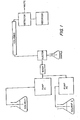
- FIG. 1 The conventional components of a two solvent liquid chromatograph are seen in Figure 1 and include solvent 1 and its pump Pl, solvent 2 and its pump P2, a sample, an injector, a column, a detector and a recorder.
- a mixer embodying features of this invention is located in series between the pumps and the injector.
- the mixing system includes one or more mixer matrices or stacks of mixer matrices, each matrix containing-one or more mixing chambers as will best be seen in Figure 2.
- the mixer in its most elementary form comprises a matrix block 2 with a pair of cover plates 4 and 6 shown separated from its opposite parallel planar faces 8 and 10 to which they are normally attached during operation.
- Each matrix includes a mixing chamber 12 (which is made by drilling completely through the matrix block 2) and two cover plates 4 and 6.
- the mixing chamber thus, in this illustrative example, is cylindrical but may assume other configurations such as non-cylindrical or multi-lobar, within the scope of this invention.
- the block and the cover plates may be made from any appropriate material; 316 stainless steel having been found to be satisfactory.
- a fluid entrance conduit 14 at the upper end of the chamber 12 is formed in the block 2 and by way of passageway 16 communicates with a fluid entrance passageway 18 formed in the surface 8 of the matrix block 2.
- the passageway 18 may be formed by scribing, electrochemical etching or coining, as for example by indenting the surface 8 of the block 2 by a hardened steel wire of the desired dimension.
- cross sectional area of the entrance passageway 18 is essentially semicircular, but if desired a mating semicircular portion could be formed in the undersurface of the block 4 whereby the passageway would in effect be circular in cross section.
- Other manufacturing techniques can produce geometries other than circular or semi-circular but which are highly acceptable.
- passageway 18 is of smaller diameter than the entrance conduit 14 whereby solvent under pressure, flowing from the pump into the mixer by way of conduit 14, is accelerated as it flows through the smaller entrance passageway 18.
- a fluid exit passageway 20 is located at the opposite or lower end of the chamber 12 in the opposite face 10 of the matrix block 2 and communicates with a second mixing chamber 12a which in turn has a fluid exit passageway 21.
- the entrance passageway 18 and the exit passageway 20 are located at the opposite ends of the mixing chamber, and they are aligned 180° from each other. Alignment of 180° is optimum, but an alignment of substantially 180° is within the scope of the invention.
- the passageways ideally lie in a common plane which includes the axis 13 of the chamber 12. In other words, they lie in a common plane which bisects the chamber along its axis.
- the exit passageway 20 of the first mixing chamber 12 is also the entrance passageway of the next adjacent mixing chamber 12a downstream.
- the mixing chamber 12 is adapted to receive fluid flowing at a high velocity from the fluid entrance passageway 18 and to produce a net fluid motion end-to-end through the chamber to the exit passageway 20.
- the entrance passageway 12 and the exit passageway 20 being located at opposite ends of the chamber are thus non-collinear with the axis of the fluid motion through the chamber which is end to end whereby the flow of the fluid entering the chamber from entrance passageway 18 is changed by the confines of the chamber 12 and its momentum superimposes upon the net fluid motion through the chamber a pattern dominated by paired counter-rotating vortices indicated by arrows in Figure 2.
- the fluid thus introduced moves in symmetrical, approximately helical paths down through the mixing chamber 12 to emerge at the bottom through exit passageway 20. Thence it moves into the next adjacent mixing chamber 12a with the process repeated. However, fluid moves from the bottom of the mixing chamber to the top to flow out through exit passageway 21.
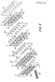
- FIG. 3 there will be seen an exploded view of a plurality of matrix blocks which, when assembled, are in stacked parallel relationship.
- a gasket comprising a thin Teflon sheet 24, only one of which is seen in Figure 3, is placed between each matrix plate and its cover plates. The entire stack is secured together by a plurality of screws 26 which pass through aligned holes 28 formed in each matrix plate and its associated cover plates as well as the gasket but not shown in the gasket.
- the matrices must be secured together under very high pressure, i.e., several thousand pounds per square inch.
- very high pressure i.e., several thousand pounds per square inch.
- the contact area is reduced by removing a portion of the surface of each matrix block 2, as at 30, leaving a plurality of marginal lands 32 and a centrally located land 34 surrounding the mixing chambers 12 and the entrance and exit passageways 18 and 21.
- FIG. 3 there are three matrix blocks in the stack designated respectively A, B, and C. Whereas the mixing chambers 12-12a in matrix block A are all of the same diameter, the chambers 12-12b in block B are larger and the chambers 12-12c in block C are still larger. All mixing chambers in a given matrix block or plate are the same diameter.
- the time of one revolution of its fluid vortices is constant assuming pressure is constant.
- the time of retention of fluid within the mixing chamber is then a function of the length of the chamber.
- the time of a revolution is less than that in a larger diameter chamber. Consequently the mixing characteristics of a mixing chamber are a function of its diameter and/or the thickness of the matrix block which determines the length of the chamber. In the present illustrative example, however, the matrix blocks are all of the same thickness for simplicity of explanation.
- any arrangement of blocks may be employed.
- three or more blocks A, or three or more B blocks, or three or more C blocks or any combination or multiples of A, B and C may be assembled.
- two A blocks and one C block may be employed, all depending on the mixing characteristics desired.
- two or more stacks of matrices may be employed in series. In its most elementary form, a mixer stack would include one each of matrix blocks A, B, and C, each block having in it a series of the same diameter mixing chambers, the diameters varying from block to block.
- Figure 4 shows a stack comprising one each of matrix blocks A, B, and C connected in series by fluid conduits.
- Figure 5 shows a stack of matrix blocks comprising two A blocks in series with each other and in series with one each of B and C size blocks.
- Figure 6 shows two stacks of one each of A, B, and C blocks connected in series. Similarly there could be more than two stacks in series and/or the stacks may vary as to the composition of matrix blocks.
- Figure 7 shows one stack having one each of A, B, and C size matrix blocks joined together in series but in addition having shunt fluid connections whereby one matrix block may be employed exclusive of the other two or two blocks may be employed in series exclusive of the third.
- solvent entering from the left as viewed in Figure 7 reaches three way valve V1 which is pre-set to direct solvent through matrix block A or to shunt it directly to valve V2.
- Valve V2 is set to direct fluid coming either from block A or its shunt to valve V3 and not back through the shunt.
- Valve V3 is set to direct the solvent through matrix block B or shunt it directly to valve V4 which permits passage of flow from either direction on to valve V5.
- Valve V5 in turn, is set to pass the solvent through matrix block C or shunt it to valve V6 and thence on'to the injector.
- Two or more stacks of matrix blocks as shown in Figure 6, with the matrices of each combined, as for example in Figure 7, can be connected together by appropriate fluid conduits and valves whereby two or more matrices of both stacks can be joined in series relationship.
- the following example is illustrative of a condition in high-pressure gradient requiring mixing. Assuming a 10% mixture of acetonitrile in water, the water pump will be operating nine times faster than the acetonitrile pump. Hence, over a unit of time there will be nine piston crossovers of the water pump to one piston crossover of the acetonitrile pump. This results in a higher frequency rippling of the baseline at the water pump crossover frequency summed with a low frequency rippling at the acetonitrile pump crossover frequency.
- the mixer shall be tuned such that its compositional averaging volume is large enough to integrate or average over the volume between acetonitrile pump crossovers. This volume will by definition be large enough to average over the more frequent water pump crossovers.
- the smallest diameter chambers are employed to attenuate higher frequency rippling with very little delay in system response time. Larger chambers are invoked when it becomes necessary to average over the successively larger volumes when pumps are operated at a slower crossover frequency.
Applications Claiming Priority (2)
| Application Number | Priority Date | Filing Date | Title |
|---|---|---|---|
| US06/574,541 US4534659A (en) | 1984-01-27 | 1984-01-27 | Passive fluid mixing system |
| US574541 | 1984-01-27 |
Publications (3)
| Publication Number | Publication Date |
|---|---|
| EP0150776A2 true EP0150776A2 (fr) | 1985-08-07 |
| EP0150776A3 EP0150776A3 (en) | 1987-08-05 |
| EP0150776B1 EP0150776B1 (fr) | 1990-10-31 |
Family
ID=24296586
Family Applications (1)
| Application Number | Title | Priority Date | Filing Date |
|---|---|---|---|
| EP85100459A Expired EP0150776B1 (fr) | 1984-01-27 | 1985-01-17 | Système passif de mélange de fluides |
Country Status (4)
| Country | Link |
|---|---|
| US (1) | US4534659A (fr) |
| EP (1) | EP0150776B1 (fr) |
| JP (1) | JPS60161723A (fr) |
| DE (1) | DE3580285D1 (fr) |
Cited By (2)
| Publication number | Priority date | Publication date | Assignee | Title |
|---|---|---|---|---|
| EP0677556A2 (fr) * | 1994-04-15 | 1995-10-18 | Toyo Ink Manufacturing Co., Ltd. | Pigment revêtu et composition colorante |
| EP1944079A3 (fr) * | 2004-06-11 | 2009-05-06 | Corning Incorporated | Conceptions de microstructures pour optimiser le mélange et la chute de pression |
Families Citing this family (39)
| Publication number | Priority date | Publication date | Assignee | Title |
|---|---|---|---|---|
| IT1188154B (it) * | 1985-03-25 | 1988-01-07 | Staser Prodotti Petroliferi Sp | Emulsionatore statico a flusso per liquidi non miscibili |
| US5094833A (en) * | 1989-01-05 | 1992-03-10 | Morton International, Inc. | High yield sodium hydrosulfite generation |
| US5066137A (en) * | 1991-03-04 | 1991-11-19 | King Leonard T | Steam injection and mixing apparatus |
| US5534328A (en) * | 1993-12-02 | 1996-07-09 | E. I. Du Pont De Nemours And Company | Integrated chemical processing apparatus and processes for the preparation thereof |
| KR100327521B1 (ko) * | 1993-03-19 | 2002-07-03 | 이.아이,듀우판드네모아앤드캄파니 | 일체형화학가공장치및그제조방법 |
| DE29500517U1 (de) * | 1995-01-14 | 1995-03-02 | Heinz Lange Gmbh Dipl Ing | Vorrichtung zum Filtern und Mischen von Gasen oder Gasgemischen |
| US5718509A (en) * | 1996-10-03 | 1998-02-17 | Instrumentation Technology Associates, Inc. | Materials dispersion apparatus with relatively slidable blocks |
| US5842787A (en) | 1997-10-09 | 1998-12-01 | Caliper Technologies Corporation | Microfluidic systems incorporating varied channel dimensions |
| DE19746583A1 (de) * | 1997-10-22 | 1999-04-29 | Merck Patent Gmbh | Mikromischer |
| AU2868099A (en) | 1998-02-13 | 1999-08-30 | Selective Genetics, Inc. | Concurrent flow mixing methods and apparatuses for the preparation of gene therapy vectors and compositions prepared thereby |
| USRE40407E1 (en) | 1999-05-24 | 2008-07-01 | Vortex Flow, Inc. | Method and apparatus for mixing fluids |
| US6299767B1 (en) * | 1999-10-29 | 2001-10-09 | Waters Investments Limited | High pressure capillary liquid chromatography solvent delivery system |
| JP2002119835A (ja) * | 2000-08-10 | 2002-04-23 | Max Co Ltd | オゾン水生成器 |
| DE10041823C2 (de) * | 2000-08-25 | 2002-12-19 | Inst Mikrotechnik Mainz Gmbh | Verfahren und statischer Mikrovermischer zum Mischen mindestens zweier Fluide |
| US6331073B1 (en) * | 2000-10-20 | 2001-12-18 | Industrial Technology Research Institute | Order-changing microfluidic mixer |
| JP4077674B2 (ja) * | 2002-07-24 | 2008-04-16 | 憲一 工藤 | ナノ/ミクロ液体クロマトグラフのグラジエント送液装置および送液方法 |
| US7094354B2 (en) * | 2002-12-19 | 2006-08-22 | Bayer Healthcare Llc | Method and apparatus for separation of particles in a microfluidic device |
| US7125711B2 (en) * | 2002-12-19 | 2006-10-24 | Bayer Healthcare Llc | Method and apparatus for splitting of specimens into multiple channels of a microfluidic device |
| DE10260691A1 (de) * | 2002-12-23 | 2004-07-08 | Technische Universität München | Vorrichtung und Verfahren zur parallelen, automatisierten Kultivierung von Zellen unter technischen Bedingungen |
| US7435381B2 (en) * | 2003-05-29 | 2008-10-14 | Siemens Healthcare Diagnostics Inc. | Packaging of microfluidic devices |
| US20040265172A1 (en) * | 2003-06-27 | 2004-12-30 | Pugia Michael J. | Method and apparatus for entry and storage of specimens into a microfluidic device |
| US20040265171A1 (en) * | 2003-06-27 | 2004-12-30 | Pugia Michael J. | Method for uniform application of fluid into a reactive reagent area |
| US7347617B2 (en) * | 2003-08-19 | 2008-03-25 | Siemens Healthcare Diagnostics Inc. | Mixing in microfluidic devices |
| US7147364B2 (en) * | 2003-09-29 | 2006-12-12 | Hitachi High-Technologies Corporation | Mixer and liquid analyzer provided with same |
| EP1992404B1 (fr) * | 2007-05-15 | 2011-03-23 | Corning Incorporated | Dispositif microfluidique et procédé pour réactions de liquides immiscibles |
| DE102008009199A1 (de) * | 2008-02-15 | 2009-08-27 | Forschungszentrum Karlsruhe Gmbh | Reaktionsmischersystem zur Vermischung und chemischer Reaktion von mindestens zwei Fluiden |
| EP2172260A1 (fr) * | 2008-09-29 | 2010-04-07 | Corning Incorporated | Dispositifs microfluidiques à flux multiple |
| AU2010257118B2 (en) | 2009-06-04 | 2014-08-28 | Lockheed Martin Corporation | Multiple-sample microfluidic chip for DNA analysis |
| CA2814720C (fr) | 2010-10-15 | 2016-12-13 | Lockheed Martin Corporation | Conception optique microfluidique |
| US9791107B2 (en) * | 2011-07-27 | 2017-10-17 | Agilent Technologies, Inc. | Packet-wise proportioning followed by immediate longitudinal mixing |
| US9322054B2 (en) | 2012-02-22 | 2016-04-26 | Lockheed Martin Corporation | Microfluidic cartridge |
| US20140334245A1 (en) * | 2013-05-08 | 2014-11-13 | Karlsruher Institut Fuer Technologie | Emulsifying arrangement |
| JP6237511B2 (ja) * | 2014-07-11 | 2017-11-29 | 東京エレクトロン株式会社 | 薬液排出機構、液処理装置、薬液排出方法、記憶媒体 |
| FR3034466B1 (fr) * | 2015-04-03 | 2018-03-16 | Safran Helicopter Engines | Limiteur de debit |
| US11035480B2 (en) * | 2016-02-24 | 2021-06-15 | Leanna Levine and Aline, Inc. | Mechanically driven sequencing manifold |
| US11185830B2 (en) | 2017-09-06 | 2021-11-30 | Waters Technologies Corporation | Fluid mixer |
| WO2021030245A1 (fr) | 2019-08-12 | 2021-02-18 | Waters Technologies Corporation | Mélangeur pour système de chromatographie |
| EP4179310A1 (fr) | 2020-07-07 | 2023-05-17 | Waters Technologies Corporation | Mélangeur pour chromatographie en phase liquide |
| CN116194767A (zh) | 2020-09-22 | 2023-05-30 | 沃特世科技公司 | 连续流混合器 |
Citations (4)
| Publication number | Priority date | Publication date | Assignee | Title |
|---|---|---|---|---|
| US3323550A (en) * | 1964-05-21 | 1967-06-06 | Lee Co | Fluid resistor |
| US3856270A (en) * | 1973-10-09 | 1974-12-24 | Fmc Corp | Static fluid mixing apparatus |
| US3986957A (en) * | 1973-12-10 | 1976-10-19 | Vortex S.A. | Apparatus for treating a liquid |
| US4087862A (en) * | 1975-12-11 | 1978-05-02 | Exxon Research & Engineering Co. | Bladeless mixer and system |
Family Cites Families (5)
| Publication number | Priority date | Publication date | Assignee | Title |
|---|---|---|---|---|
| US3089683A (en) * | 1960-06-08 | 1963-05-14 | Horace F Thomas | Mixer for viscous liquids |
| US3382534A (en) * | 1965-08-19 | 1968-05-14 | Monsanto Co | Plate type fluid mixer |
| GB1160401A (en) * | 1967-02-15 | 1969-08-06 | British Motor Corp Ltd | Mixing Liquids. |
| US4062524A (en) * | 1973-06-06 | 1977-12-13 | Bayer Aktiengesellschaft | Apparatus for the static mixing of fluid streams |
| JPS58171225U (ja) * | 1982-05-10 | 1983-11-15 | 荏原インフイルコ・エンジニアリング・サ−ビス株式会社 | 混合装置 |
-
1984
- 1984-01-27 US US06/574,541 patent/US4534659A/en not_active Expired - Lifetime
-
1985
- 1985-01-17 EP EP85100459A patent/EP0150776B1/fr not_active Expired
- 1985-01-17 DE DE8585100459T patent/DE3580285D1/de not_active Expired - Lifetime
- 1985-01-24 JP JP60010004A patent/JPS60161723A/ja active Granted
Patent Citations (4)
| Publication number | Priority date | Publication date | Assignee | Title |
|---|---|---|---|---|
| US3323550A (en) * | 1964-05-21 | 1967-06-06 | Lee Co | Fluid resistor |
| US3856270A (en) * | 1973-10-09 | 1974-12-24 | Fmc Corp | Static fluid mixing apparatus |
| US3986957A (en) * | 1973-12-10 | 1976-10-19 | Vortex S.A. | Apparatus for treating a liquid |
| US4087862A (en) * | 1975-12-11 | 1978-05-02 | Exxon Research & Engineering Co. | Bladeless mixer and system |
Cited By (5)
| Publication number | Priority date | Publication date | Assignee | Title |
|---|---|---|---|---|
| EP0677556A2 (fr) * | 1994-04-15 | 1995-10-18 | Toyo Ink Manufacturing Co., Ltd. | Pigment revêtu et composition colorante |
| EP0677556A3 (fr) * | 1994-04-15 | 1997-02-26 | Toyo Ink Mfg Co | Pigment revêtu et composition colorante. |
| US5795376A (en) * | 1994-04-15 | 1998-08-18 | Toyo Ink Manufacturing Co., Ltd. | Coated pigment and colorant composition |
| EP1944079A3 (fr) * | 2004-06-11 | 2009-05-06 | Corning Incorporated | Conceptions de microstructures pour optimiser le mélange et la chute de pression |
| US7753580B2 (en) | 2004-06-11 | 2010-07-13 | Corning, Incorporated | Microstructure designs for optimizing mixing and pressure drop |
Also Published As
| Publication number | Publication date |
|---|---|
| DE3580285D1 (de) | 1990-12-06 |
| EP0150776A3 (en) | 1987-08-05 |
| JPS60161723A (ja) | 1985-08-23 |
| US4534659A (en) | 1985-08-13 |
| EP0150776B1 (fr) | 1990-10-31 |
| JPH0446174B2 (fr) | 1992-07-29 |
Similar Documents
| Publication | Publication Date | Title |
|---|---|---|
| US4534659A (en) | Passive fluid mixing system | |
| US5887977A (en) | Stationary in-line mixer | |
| US4475821A (en) | Mixing chamber | |
| US4625569A (en) | Liquid injection device | |
| US4636315A (en) | Fluid separator apparatus and method | |
| US6890489B2 (en) | Mass rate attenuator | |
| DE112016003938B4 (de) | Flüssigkeitsentgasungsvorrichtung, Entgasungsvorrichtung und Verfahren zur Verringerung einer Zielgaskonzentration in einem Fluid | |
| US5595650A (en) | Device and a method for the separation of fluid substances | |
| US5340476A (en) | High efficiency packed column supercritical fluid chromatography | |
| US3934456A (en) | Solvent gradient generator for chromatography systems | |
| US20090294344A1 (en) | Fluid mixer assembly | |
| DE112015000770T5 (de) | Volumetrische Strömungsregulierung in mehrdimensionalen Flüssigkeitsanalysesystemen | |
| US3374606A (en) | Method of and apparatus for chromatographic separations | |
| WO2002056006A9 (fr) | Systeme de chromatographie haute performance haut debit | |
| US7132650B1 (en) | High throughput multi-dimensional sample analysis | |
| US3623704A (en) | Static mixing device | |
| DE2263769B1 (de) | Mischvorrichtung | |
| US5139680A (en) | Method for continuous multicomponent separation using anisotropic separation bed | |
| US3436897A (en) | Method of and apparatus for chromatographic separations | |
| JPH02167469A (ja) | 液体クロマトグラフィー用の溶媒混合器 | |
| US11898999B2 (en) | Mixer for liquid chromatography | |
| EP0377202A2 (fr) | Procédé et dispositif pour mélanger de petits volumes | |
| DE102006058026A1 (de) | HPLC-Anlage | |
| DD255002A1 (de) | Verfahren und vorrichtung zur erzeugung eines probenstroms fuer kontinuierliche analysenautomaten | |
| US20220011276A1 (en) | Combination mixer arrangement for noise reduction in liquid chromatography |
Legal Events
| Date | Code | Title | Description |
|---|---|---|---|
| PUAI | Public reference made under article 153(3) epc to a published international application that has entered the european phase |
Free format text: ORIGINAL CODE: 0009012 |
|
| AK | Designated contracting states |
Designated state(s): CH DE FR GB LI NL SE |
|
| PUAL | Search report despatched |
Free format text: ORIGINAL CODE: 0009013 |
|
| AK | Designated contracting states |
Kind code of ref document: A3 Designated state(s): CH DE FR GB LI NL SE |
|
| 17P | Request for examination filed |
Effective date: 19870729 |
|
| 17Q | First examination report despatched |
Effective date: 19881010 |
|
| GRAA | (expected) grant |
Free format text: ORIGINAL CODE: 0009210 |
|
| AK | Designated contracting states |
Kind code of ref document: B1 Designated state(s): CH DE FR GB LI NL SE |
|
| REF | Corresponds to: |
Ref document number: 3580285 Country of ref document: DE Date of ref document: 19901206 |
|
| PGFP | Annual fee paid to national office [announced via postgrant information from national office to epo] |
Ref country code: SE Payment date: 19901219 Year of fee payment: 7 |
|
| ET | Fr: translation filed | ||
| PGFP | Annual fee paid to national office [announced via postgrant information from national office to epo] |
Ref country code: NL Payment date: 19910131 Year of fee payment: 7 |
|
| PLBE | No opposition filed within time limit |
Free format text: ORIGINAL CODE: 0009261 |
|
| STAA | Information on the status of an ep patent application or granted ep patent |
Free format text: STATUS: NO OPPOSITION FILED WITHIN TIME LIMIT |
|
| 26N | No opposition filed | ||
| PGFP | Annual fee paid to national office [announced via postgrant information from national office to epo] |
Ref country code: CH Payment date: 19911218 Year of fee payment: 8 |
|
| PG25 | Lapsed in a contracting state [announced via postgrant information from national office to epo] |
Ref country code: SE Effective date: 19920118 |
|
| PG25 | Lapsed in a contracting state [announced via postgrant information from national office to epo] |
Ref country code: NL Effective date: 19920801 |
|
| NLV4 | Nl: lapsed or anulled due to non-payment of the annual fee | ||
| PGFP | Annual fee paid to national office [announced via postgrant information from national office to epo] |
Ref country code: FR Payment date: 19921210 Year of fee payment: 9 |
|
| PGFP | Annual fee paid to national office [announced via postgrant information from national office to epo] |
Ref country code: DE Payment date: 19921211 Year of fee payment: 9 |
|
| PGFP | Annual fee paid to national office [announced via postgrant information from national office to epo] |
Ref country code: GB Payment date: 19921231 Year of fee payment: 9 |
|
| PG25 | Lapsed in a contracting state [announced via postgrant information from national office to epo] |
Ref country code: LI Effective date: 19930131 Ref country code: CH Effective date: 19930131 |
|
| REG | Reference to a national code |
Ref country code: CH Ref legal event code: PL |
|
| PG25 | Lapsed in a contracting state [announced via postgrant information from national office to epo] |
Ref country code: GB Effective date: 19940117 |
|
| GBPC | Gb: european patent ceased through non-payment of renewal fee |
Effective date: 19940117 |
|
| PG25 | Lapsed in a contracting state [announced via postgrant information from national office to epo] |
Ref country code: FR Effective date: 19940930 |
|
| PG25 | Lapsed in a contracting state [announced via postgrant information from national office to epo] |
Ref country code: DE Effective date: 19941001 |
|
| REG | Reference to a national code |
Ref country code: FR Ref legal event code: ST |
|
| EUG | Se: european patent has lapsed |
Ref document number: 85100459.8 Effective date: 19920806 |