EP0149379B1 - Elément de suspension hydropneumatique de véhicule, notamment suspension oléopneumatique destinée à équiper des véhicules lourds, et suspension constituée de tels éléments - Google Patents
Elément de suspension hydropneumatique de véhicule, notamment suspension oléopneumatique destinée à équiper des véhicules lourds, et suspension constituée de tels éléments Download PDFInfo
- Publication number
- EP0149379B1 EP0149379B1 EP84402505A EP84402505A EP0149379B1 EP 0149379 B1 EP0149379 B1 EP 0149379B1 EP 84402505 A EP84402505 A EP 84402505A EP 84402505 A EP84402505 A EP 84402505A EP 0149379 B1 EP0149379 B1 EP 0149379B1
- Authority
- EP
- European Patent Office
- Prior art keywords
- heat pipe
- suspension
- vehicle
- cylinder
- gas
- Prior art date
- Legal status (The legal status is an assumption and is not a legal conclusion. Google has not performed a legal analysis and makes no representation as to the accuracy of the status listed.)
- Expired
Links
- 239000000725 suspension Substances 0.000 title claims description 63
- 239000007789 gas Substances 0.000 claims description 48
- 239000006096 absorbing agent Substances 0.000 claims description 12
- 230000035939 shock Effects 0.000 claims description 12
- 239000007788 liquid Substances 0.000 claims description 11
- 238000001816 cooling Methods 0.000 claims description 10
- 238000010438 heat treatment Methods 0.000 claims description 9
- 238000007789 sealing Methods 0.000 claims description 4
- 239000012530 fluid Substances 0.000 claims description 3
- XLYOFNOQVPJJNP-UHFFFAOYSA-N water Substances O XLYOFNOQVPJJNP-UHFFFAOYSA-N 0.000 claims description 3
- 230000001105 regulatory effect Effects 0.000 claims description 2
- 238000001704 evaporation Methods 0.000 claims 1
- 238000013016 damping Methods 0.000 description 12
- 239000012528 membrane Substances 0.000 description 7
- 230000007423 decrease Effects 0.000 description 6
- IJGRMHOSHXDMSA-UHFFFAOYSA-N Atomic nitrogen Chemical compound N#N IJGRMHOSHXDMSA-UHFFFAOYSA-N 0.000 description 5
- 230000000694 effects Effects 0.000 description 3
- 210000000056 organ Anatomy 0.000 description 3
- 238000006073 displacement reaction Methods 0.000 description 2
- 238000002347 injection Methods 0.000 description 2
- 239000007924 injection Substances 0.000 description 2
- 229910052757 nitrogen Inorganic materials 0.000 description 2
- 238000005096 rolling process Methods 0.000 description 2
- 229910000906 Bronze Inorganic materials 0.000 description 1
- RYGMFSIKBFXOCR-UHFFFAOYSA-N Copper Chemical compound [Cu] RYGMFSIKBFXOCR-UHFFFAOYSA-N 0.000 description 1
- 229910000881 Cu alloy Inorganic materials 0.000 description 1
- LFQSCWFLJHTTHZ-UHFFFAOYSA-N Ethanol Chemical compound CCO LFQSCWFLJHTTHZ-UHFFFAOYSA-N 0.000 description 1
- 241001080024 Telles Species 0.000 description 1
- 238000010521 absorption reaction Methods 0.000 description 1
- 238000013459 approach Methods 0.000 description 1
- 230000003416 augmentation Effects 0.000 description 1
- 239000010974 bronze Substances 0.000 description 1
- 238000006243 chemical reaction Methods 0.000 description 1
- 230000001276 controlling effect Effects 0.000 description 1
- 239000010949 copper Substances 0.000 description 1
- 229910052802 copper Inorganic materials 0.000 description 1
- KUNSUQLRTQLHQQ-UHFFFAOYSA-N copper tin Chemical compound [Cu].[Sn] KUNSUQLRTQLHQQ-UHFFFAOYSA-N 0.000 description 1
- 230000007547 defect Effects 0.000 description 1
- 238000010586 diagram Methods 0.000 description 1
- 230000005611 electricity Effects 0.000 description 1
- 210000001061 forehead Anatomy 0.000 description 1
- 230000005484 gravity Effects 0.000 description 1
- 230000017525 heat dissipation Effects 0.000 description 1
- 238000009434 installation Methods 0.000 description 1
- 238000012423 maintenance Methods 0.000 description 1
- 238000004519 manufacturing process Methods 0.000 description 1
- 239000000463 material Substances 0.000 description 1
- 239000000203 mixture Substances 0.000 description 1
- 230000010355 oscillation Effects 0.000 description 1
- 230000021715 photosynthesis, light harvesting Effects 0.000 description 1
- 239000004576 sand Substances 0.000 description 1
- 230000001932 seasonal effect Effects 0.000 description 1
- 238000000926 separation method Methods 0.000 description 1
- 239000000243 solution Substances 0.000 description 1
Images


Classifications
-
- F—MECHANICAL ENGINEERING; LIGHTING; HEATING; WEAPONS; BLASTING
- F16—ENGINEERING ELEMENTS AND UNITS; GENERAL MEASURES FOR PRODUCING AND MAINTAINING EFFECTIVE FUNCTIONING OF MACHINES OR INSTALLATIONS; THERMAL INSULATION IN GENERAL
- F16F—SPRINGS; SHOCK-ABSORBERS; MEANS FOR DAMPING VIBRATION
- F16F9/00—Springs, vibration-dampers, shock-absorbers, or similarly-constructed movement-dampers using a fluid or the equivalent as damping medium
- F16F9/32—Details
- F16F9/42—Cooling arrangements
-
- B—PERFORMING OPERATIONS; TRANSPORTING
- B62—LAND VEHICLES FOR TRAVELLING OTHERWISE THAN ON RAILS
- B62D—MOTOR VEHICLES; TRAILERS
- B62D55/00—Endless track vehicles
- B62D55/08—Endless track units; Parts thereof
- B62D55/104—Suspension devices for wheels, rollers, bogies or frames
- B62D55/112—Suspension devices for wheels, rollers, bogies or frames with fluid springs, e.g. hydraulic pneumatic
- B62D55/1125—Hydro-pneumatic or pneumatic, e.g. air-cushioned
Definitions
- the present invention relates to a hydropneumatic vehicle suspension element, in particular oleopneumatic suspension intended to equip heavy vehicles, such as armored vehicles.
- an oleopneumatic suspension element comprises a piston movable in a cylinder, a gas accumulator integral with the cylinder and containing gas as well as a liquid separated from the gas by a flexible membrane, and a damping cartridge placed in the liquid between the piston and the diaphragm.
- Damping is elegantly and conveniently obtained by forcing the oil to pass through the diffusers of the cartridge, thus creating, when the piston moves in one direction or the other, a pressure drop all the higher as the speed is great.
- the invention aims to eliminate these drawbacks by proposing a simple, reliable and much less expensive solution than the devices recalled above.
- the means for cooling the liquid of the suspension element comprise a heat pipe connecting the damping cartridge which forms a hot source, to a cold source constituted by the chassis of the vehicle or by a free surface of the element itself.
- the heat pipe containing a gas which can evaporate on contact with the cartridge, then move to the cold source where it condenses, and then return to the cartridge forming an evaporator by repeating the cycle, the cold source being located above the hot spring formed by the damping cartridge.
- the heat pipe is integrated into the suspension element so that it is capable of bringing the temperature of the damper to an almost constant thermal potential, materialized by the chassis of the vehicle or by a free surface of the element. suspension.
- the chassis temperature being relatively uniform, each suspension element is thus forced to operate at a temperature which practically depends only on climatic or seasonal conditions.
- the heat pipe constitutes a high-flow heat sink which limits the operating temperature of the oil, and therefore keeps the ground clearance of the vehicle substantially constant.
- the heat pipe consists of a closed conduit extending from the interior of the damping cartridge to a free surface of a body fixed to the cylinder and crossed by a support arm. wheel, this duct being arranged in the wall of the cylinder and in the body, and means are provided for sealing the duct when the cylinder wall passes through the body.
- the invention also aims to provide a device for varying the ground clearance of the vehicle, which is indeed advantageous under certain conditions of use of heavy vehicles, for example on muddy or sandy terrain in which the vehicle may get bogged down.
- the heat pipe opens, beyond its end situated in the cold source, into an enclosure containing an incondensable gas in the range of temperatures considered for the suspension element and its damping cartridge, as well as a heat source such as a heating resistor, the adjustment of which makes it possible to move a front between the two gases, and consequently the temperature of the element liquid and the ground clearance of the vehicle.
- an element 1 of oleopneumatic suspension conventionally comprising a piston 2 movable in a cylinder 3, a gas accumulator 4 internally provided with a flexible membrane 5 for separation between a volume 6 of gas and the oil 7 filling the space between the piston 2 and the membrane 5, as well as a damping cartridge 8 placed in the liquid 7 between the piston 2 and the membrane 5.
- a gas accumulator 4 internally provided with a flexible membrane 5 for separation between a volume 6 of gas and the oil 7 filling the space between the piston 2 and the membrane 5, as well as a damping cartridge 8 placed in the liquid 7 between the piston 2 and the membrane 5.
- the element 1 is also provided with means for cooling the oil 7 and correspondingly for adjusting the ground clearance of the vehicle chassis.
- these means comprise a heat pipe 9 schematically shown, connecting the damping cartridge 8 which forms a hot source, to a cold source 11 which can be the chassis of the vehicle or a free surface of the element 1 itself.
- the heat pipe 9 is a pipe containing a gas which can evaporate on contact with the cartridge 8, then move as indicated by arrows to the opposite end of the pipe, in the cold source 11 where the calories transported by the gas are dissipated (arrows F), the gas condensing into fine droplets at this end of the heat pipe 9.
- the cold source 11 being located above the hot source constituted by the cartridge 8 forming an evaporator, the condensed gas droplets gradually descend along the wall of the heat pipe 9, then evaporate again in the cartridge 8, after which the previous cycle begins again, during the entire operation of the suspension element 1, that is to say during the movements of the vehicle incorporating a series of these elements.
- the oil under pressure 7 is discharged into the accumulator 4 where it compresses or expands the gas 6.
- the oil passes through the cartridge 8 where it dissipates energy in the form of heat. Thanks to the presence of the heat pipe 9 which originates inside the damper 8, the heat energy which gradually heats the oil is mainly evacuated by the heat pipe 9 to the cold source 11.
- this cold source 11 is the chassis of the vehicle, the temperature of which varies little from one point to another, the various suspension elements 1 dissipate their heat towards cold sources which are substantially at the same temperature, these being the average temperature of the chassis. This has the advantage of limiting asymmetries due to temperature differences when stopped.
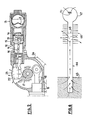
- FIG. 2 shows a suspension element 12 comprising a gas accumulator 13, a damping cartridge 14, a cylinder 15, a piston 16 cooperating in a manner known per se with a wheel support arm 17 (the latter not being not shown), this arm 17 also being associated with another piston 16 of a second suspension element identical to element 12.
- Each piston 16 carries a rod 18 cooperating in a known manner with the arm 17.
- Each element such as 12 is provided with a heat pipe 19 schematically represented, constituted by a conduit originating in a chamber 21 inside the damper 14 and which terminates in a closed compartment 22, contiguous to the free surface 23 of a body 24 coaxial with the arm 17 and to which the cylinders 15 are fixed.
- a heat pipe 19 schematically represented, constituted by a conduit originating in a chamber 21 inside the damper 14 and which terminates in a closed compartment 22, contiguous to the free surface 23 of a body 24 coaxial with the arm 17 and to which the cylinders 15 are fixed.
- the operation of the heat pipe 19 is the same as that described with reference to FIG. 1, with the particularity that the cold source is here constituted by the free surface 23 of the body 24 of the suspension element 12 itself.
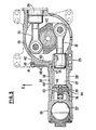
- FIG. 3 illustrates an industrial embodiment of a suspension element 25 comprising in a known manner, as in the previous cases, a gas accumulator 26 with flexible membrane 27, a cylinder 28 containing a sliding piston 29 extended by a rod 31 which cooperates with a wheel support arm 32 housed in a casing 33 coaxial with this arm, which is also associated with a second piston 34 identical to the piston 29 and similarly provided with a rod 35.
- the arm 32 therefore cooperates with two identical suspension elements 25, having a common body 33 fixed to their respective cylinders 28, each element 25 being equipped with a damping cartridge 36 traversed by the oil 37 alternately in each direction during the movements of the pistons 29, 34.
- each element 25 is provided with a heat pipe 38 consisting of a closed conduit, one end of which is formed by a chamber 39 arranged inside the cartridge 36 coaxial thereto, and whose l the opposite end 41 is contiguous with a free surface 42 of the casing 33.
- the conduit 38 has a first section 43 formed radially in the cartridge 36, and which opens into the wall of the cylinder 28, a second section 44 formed in the wall of the cylinder 28, and which opens at 44a into the cater 33, and finally a third section 45 which extends radially in the casing 33 to the end 41.
- the cartridges 36 each comprise a cylindrical part 80 in which the section 43 of the heat pipe 38 is formed.
- the parts 80, as well as the pistons 29, are made of a material with good thermal conduction and good thermal capacity, such as copper or a copper alloy (bronze).
- O-rings 46 and 47 seal respectively between the shock absorber 36 and the cylinder 28, and between the latter and the casing 33, in line with the conduit 38 containing a condensable gas suitable for the temperature range considered, and the tightness is thus guaranteed.
- Fins 48 are provided on the surface of the casing 33 in line with section 45, in order to facilitate the evacuation of the heat towards the outside, the end 41 being closed by a screw 49.
- the condensed gas for example a freon
- the top of the element 25 being indicated by the arrow K, that is to say that the end 41 is situated at a level above the ground above the chamber 39, the gas rises through the sections 43, 44 and 45 to the end 41 constituting a cold source where it condenses into fine droplets, while the calories transported by the gas are gradually evacuated from section 45 and through the end 41 through the casing 33 and its free surface 42.
- the condensed gas droplets formed in the condenser 41 then descend progressively towards the chamber 39 forming an evaporator, through sections 45, 44 and 43, where they evaporate again, so that the previous cycle begins again .
- each element 51 comprises a gas accumulator 54, a damping cartridge 55, a cylinder 56 containing a piston 57, and a heat pipe 58 connecting a chamber 59 formed in the cartridge 55 coaxially thereto, to a cold source constituted by the chassis 52.
- Each heat pipe 59 thus comprises, between the terminal chamber 59, a first section 61 in the cartridge 55, a second section 62 in the wall of the cylinder 56, and a third section 63 arranged in the frame 52 and which constitutes the cold source or condenser .
- the sections 61, 63 are formed radially to the general axis of the elements 51, while the sections 59 extend approximately parallel to this axis, so that, the vehicle being assumed on a horizontal plane, the sections 63 are located at a height above the ground greater than that of sections 61.
- the operation of the heat pipes 59 is the same as that of the preceding embodiments, with respect to those of FIGS. 2 and 3, the particularity according to which the cold source is constituted by the chassis 52 of the vehicle, and not by a free surface of the body of the suspension element.
- each suspension element 51 although isolated or independent, thus keeps a constant ground clearance identical to that of the other elements.
- the presence of the heat pipes makes it possible to thermally control the oil in the suspension by limiting its temperature to the maximum admissible value for the mechanical organs of the suspension, and this with great reliability: indeed, this control device has no moving parts, and the fact that each heat pipe thermal circuit associated with an element is independent of the other circuits and other elements, a possible failure of a circuit has no effect on the operation of neighboring circuits, so that there is no propagation of said failure.
- FIG. 6 shows the principle of implementing a heat pipe 64 connecting an evaporator 65 (hot source) of a suspension element to a cold source (condenser 66) with an enclosure 67 containing an incondensable gas in the temperature range considered for the suspension element and its evaporator 65, a heat source such as a heating resistor 70 being placed in the enclosure 67.
- a heat pipe 64 connecting an evaporator 65 (hot source) of a suspension element to a cold source (condenser 66) with an enclosure 67 containing an incondensable gas in the temperature range considered for the suspension element and its evaporator 65, a heat source such as a heating resistor 70 being placed in the enclosure 67.
- the volume of the enclosure 67 is large compared to that of the heat pipe 64, for example about one liter for a heat pipe 64 having a capacity of 100 cm 3 .
- the heat pipe 64 and the enclosure 67 are filled with a mixture of two gases, one condensable, the other noncondensable in the range of targeted temperatures.
- the condensable fluid can be for example an alcohol, an oil, a freon, or water, fluids which can coexist in the liquid state and in the gaseous state in the temperature range of the element.
- the temperature of the suspension element is normally between -40 ° C and + 60 ° C, which are the extreme atmospheric temperatures in which the vehicle can be used, the temperature of the damper or evaporator being between 60 and 140 ° C and normally about 90 ° C.
- the two gases are mixed and droplets of the condensable gas are deposited in the vicinity of the coldest tips, that is to say on the wall of the heat pipe passing through the cold source 66. If the evaporator 65, the heat pipe 64 and the enclosure 67 are at equal temperatures, this distribution is almost uniform, and the incondensable gas fills almost the entire volume of the heat pipe 64 and the enclosure 67.
- the absorption of calories at the hot source 65 evaporates the condensable gas which moves towards the cold source 66 following the path symbolized by the arrows.
- the condensable gas is liquefied on the interior wall at the cold source 66 in which the calories are discharged, then brought back to the hot source 65 by capillarity, gravity, etc.
- the noncondensable gas is evacuated from the heat pipe 64 and discharged into the enclosure 67, so that a "front” 68 is formed between the condensable gas and the noncondensable gas, this "front” normally being located between the ends of the cold source 66 and very “stiff”, that is to say that in normal operation, it can move over one or two millimeters.
- the "front" 68 is moved along the heat pipe 64. If the temperature in the enclosure 67 is raised, the front 68 moves in the direction of the evaporator 65, so that the cooling surface offered in the cold source 66 to the condensable gas decreases. As a result, the quantity of calories removed from the evaporator 65 decreases, and consequently, the temperature of the damping cartridge forming the evaporator 65 increases, as does that of the oil. As a result, the ground clearance of the vehicle chassis increases.
- Such a device makes it possible to adjust the height above the ground of the vehicle chassis, only by regulating the heating in the enclosure 67 by the resistor 70.
- this device is only active when the vehicle is moving and then there is energy dissipation.
- Such a ground clearance control device is of certain interest in particular circumstances of use of heavy vehicles, for example on muddy or sandy terrain. Indeed, increasing the ground clearance of the vehicle can then prevent it from being “sucked” by the mud in which it sinks, or from remaining stuck in the sand.
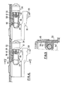
- FIG. 7 shows an industrial implementation of the device for controlling the ground clearance of a vehicle, the principle of which is shown diagrammatically in FIG. 6.
- the suspension element 25 is here identical to that of FIG. 3.
- the section 60 of the heat pipe 50 communicates with a tank or enclosure 69 whose capacity is much greater than that of the heat pipe 50 and which is internally provided with a heating resistance 71.
- This enclosure or bulb 69 contains an incondensable gas in the targeted temperature range, and is provided with a nozzle 72 pressed in a sealed manner in the body 33 to be connected with the section 45 of the heat pipe 50.
- the sealing between the enclosure 69 and body 33 is provided by an O-ring 73.
- a plug 74 placed at the top of the enclosure 69 allows the filling thereof with the noncondensable gas.
- Each element of the vehicle suspension can thus be fitted with an enclosure 69 supplied with electricity by a suitable source such as the vehicle battery.
- a tube containing the condenser gas can be housed in the pipe constituting the heat pipe.
- the heat pipe provided by the invention only begins to extract the calories produced by the shock absorber (8, 14, 36, 55) only from a variable temperature threshold according to the type of heat pipe.
- this threshold allows rapid heating of the oil at low temperature by rolling effect, the heat pipe being blocked. Beyond the temperature threshold corresponding to the heat pipe, it begins to operate with increasing efficiency to transfer the calories produced during rolling.
Landscapes
- Engineering & Computer Science (AREA)
- Mechanical Engineering (AREA)
- General Engineering & Computer Science (AREA)
- Chemical & Material Sciences (AREA)
- Combustion & Propulsion (AREA)
- Transportation (AREA)
- Vehicle Body Suspensions (AREA)
- Fluid-Damping Devices (AREA)
Applications Claiming Priority (2)
| Application Number | Priority Date | Filing Date | Title |
|---|---|---|---|
| FR8320063 | 1983-12-14 | ||
| FR8320063A FR2556804B1 (fr) | 1983-12-14 | 1983-12-14 | Element de suspension hydropneumatique de vehicule, notamment suspension oleopneumatique destinee a equiper des vehicules lourds, et suspension constituee de tels elements |
Publications (2)
| Publication Number | Publication Date |
|---|---|
| EP0149379A1 EP0149379A1 (fr) | 1985-07-24 |
| EP0149379B1 true EP0149379B1 (fr) | 1987-12-09 |
Family
ID=9295186
Family Applications (1)
| Application Number | Title | Priority Date | Filing Date |
|---|---|---|---|
| EP84402505A Expired EP0149379B1 (fr) | 1983-12-14 | 1984-12-05 | Elément de suspension hydropneumatique de véhicule, notamment suspension oléopneumatique destinée à équiper des véhicules lourds, et suspension constituée de tels éléments |
Country Status (8)
| Country | Link |
|---|---|
| US (1) | US4629169A (https=) |
| EP (1) | EP0149379B1 (https=) |
| JP (1) | JPS60146709A (https=) |
| BR (1) | BR8406405A (https=) |
| CA (1) | CA1228083A (https=) |
| DE (1) | DE3468063D1 (https=) |
| FR (1) | FR2556804B1 (https=) |
| IN (1) | IN162984B (https=) |
Cited By (1)
| Publication number | Priority date | Publication date | Assignee | Title |
|---|---|---|---|---|
| DE102009034295A1 (de) * | 2009-07-21 | 2011-02-03 | Dt Swiss Ag | Dämpfereinrichtung für ein Zweirad |
Families Citing this family (17)
| Publication number | Priority date | Publication date | Assignee | Title |
|---|---|---|---|---|
| FR2597952B1 (fr) * | 1986-04-29 | 1990-11-09 | Applic Mach Motrices | Clapet d'ecretage a ouverture rapide pour element de suspension hydropneumatique de vehicule lourd |
| FR2609131B1 (fr) * | 1986-12-26 | 1989-12-08 | Applic Mach Motrices | Amortisseur pour element de suspension hydropneumatique de vehicule et dispositif incorporant cet amortisseur et un clapet d'ecretage double sens a ouverture rapide |
| FR2609130B1 (fr) * | 1986-12-26 | 1989-12-08 | Applic Mach Motrices | Clapet d'ecretage double sens a ouverture rapide pour element de suspension hydropneumatique de vehicule, notamment vehicule lourd et dispositif d'amortissement et d'ecretage comprenant ce clapet |
| HU207382B (en) * | 1987-09-02 | 1993-03-29 | Taurus Gumiipari Vallalat | Air spring particularly for extreme stress |
| FR2640339B1 (fr) * | 1988-12-09 | 1993-01-22 | Peugeot | Amortisseur hydraulique destine a equiper un organe de suspension, par exemple d'un vehicule automobile |
| IT1271171B (it) * | 1993-04-08 | 1997-05-27 | Fichtel & Sachs Ag | Ammortizzatore operante selettivamente nella frequenza |
| RU2102640C1 (ru) * | 1995-12-27 | 1998-01-20 | Научно-исследовательский институт тепловозов и путевых машин | Гидропневматическая рессора рельсового транспортного средства |
| US20040021287A1 (en) * | 2002-07-29 | 2004-02-05 | Sean Timoney | Suspension unit |
| RU2266443C1 (ru) * | 2004-04-07 | 2005-12-20 | Федеральное государственное унитарное предприятие Всероссийский научно-исследовательский и конструкторско-технологический институт подвижного состава Министерства путей сообщения Российской Федерации (ФГУП ВНИКТИ МПС России) | Пневматическая рессора рельсового транспортного средства |
| WO2006010207A1 (en) * | 2004-07-29 | 2006-02-02 | Graeme Kershaw Robertson | Cooling of vehicle suspension systems |
| DE102005013413A1 (de) * | 2005-03-23 | 2006-10-05 | Stabilus Gmbh | Gasfeder |
| EP2052889B1 (de) | 2007-10-26 | 2016-06-15 | Strömsholmen AB | Hydropneumatische Feder-Dämpfungsvorrichtung und Verfahren zum Betreiben einer Hydropneumatischen Feder-Dämpfungsvorrichtung |
| CA2608825A1 (en) * | 2007-10-26 | 2009-04-26 | Multimatic Inc. | In wheel suspension system |
| DE102008026680A1 (de) * | 2008-06-04 | 2009-12-17 | Rheinmetall Landsysteme Gmbh | Hydropneumatische Dämpfereinrichtung |
| US20230133580A1 (en) | 2020-03-30 | 2023-05-04 | Sunsho Pharmaceutical Co., Ltd. | Menthol-containing composition |
| CN112498531B (zh) * | 2020-11-30 | 2022-05-17 | 浙江嘉宏运动器材有限公司 | 一种多级缓冲防颠簸自行车坐垫杆 |
| US12291325B2 (en) | 2023-07-18 | 2025-05-06 | Goodrich Corporation | Temperature compensated landing gear shock strut |
Family Cites Families (11)
| Publication number | Priority date | Publication date | Assignee | Title |
|---|---|---|---|---|
| US2949315A (en) * | 1957-05-16 | 1960-08-16 | Tayco Dev | Compressible liquid vehicle suspension and power system |
| FR1256029A (fr) * | 1960-02-02 | 1961-03-17 | Applic Ind Soc Et | Dispositif porteur et amortisseur oléo-pneumatique perfectionné pour suspension de véhicule |
| DE1233662B (de) * | 1963-08-06 | 1967-02-02 | Hymate Ges Fuer Hydraulische A | Vorrichtung zum Kuehlen von Schwingungsdaempfern |
| US3602470A (en) * | 1969-05-28 | 1971-08-31 | Fmc Corp | Hydropneumatic suspension unit |
| US3660784A (en) * | 1970-08-28 | 1972-05-02 | Raytheon Co | Energy absorber and evaporative cooling system |
| JPS4837572A (https=) * | 1971-09-17 | 1973-06-02 | ||
| DE7518252U (de) * | 1975-06-07 | 1981-12-17 | Thyssen Industrie Ag, 4300 Essen | Hydropneumatisches Federelement |
| US4061320A (en) * | 1976-05-03 | 1977-12-06 | Joe Frank Warner | Two cylinder shock absorber system |
| US4156536A (en) * | 1977-03-28 | 1979-05-29 | Pneumo Corporation | Hydropneumatic suspension system |
| JPS5826874Y2 (ja) * | 1979-01-19 | 1983-06-10 | スズキ株式会社 | オ−トバイ等に用いるクツシヨンユニツトの冷却装置 |
| FR2487737A1 (fr) * | 1980-07-29 | 1982-02-05 | Messier Auto Ind | Suspension oleopneumatique |
-
1983
- 1983-12-14 FR FR8320063A patent/FR2556804B1/fr not_active Expired
-
1984
- 1984-12-05 DE DE8484402505T patent/DE3468063D1/de not_active Expired
- 1984-12-05 EP EP84402505A patent/EP0149379B1/fr not_active Expired
- 1984-12-10 IN IN972/MAS/84A patent/IN162984B/en unknown
- 1984-12-12 US US06/680,692 patent/US4629169A/en not_active Expired - Lifetime
- 1984-12-13 BR BR8406405A patent/BR8406405A/pt not_active IP Right Cessation
- 1984-12-13 CA CA000470045A patent/CA1228083A/en not_active Expired
- 1984-12-14 JP JP59264377A patent/JPS60146709A/ja active Granted
Cited By (1)
| Publication number | Priority date | Publication date | Assignee | Title |
|---|---|---|---|---|
| DE102009034295A1 (de) * | 2009-07-21 | 2011-02-03 | Dt Swiss Ag | Dämpfereinrichtung für ein Zweirad |
Also Published As
| Publication number | Publication date |
|---|---|
| US4629169A (en) | 1986-12-16 |
| CA1228083A (en) | 1987-10-13 |
| JPS60146709A (ja) | 1985-08-02 |
| FR2556804A1 (fr) | 1985-06-21 |
| JPH033817B2 (https=) | 1991-01-21 |
| FR2556804B1 (fr) | 1987-01-30 |
| DE3468063D1 (en) | 1988-01-21 |
| BR8406405A (pt) | 1985-10-08 |
| IN162984B (https=) | 1988-07-30 |
| EP0149379A1 (fr) | 1985-07-24 |
Similar Documents
| Publication | Publication Date | Title |
|---|---|---|
| EP0149379B1 (fr) | Elément de suspension hydropneumatique de véhicule, notamment suspension oléopneumatique destinée à équiper des véhicules lourds, et suspension constituée de tels éléments | |
| FR2728037A1 (fr) | Structure heterogene d'accumulation ou de dissipation d'energie, procedes d'utilisation d'une telle structure, et appareils associes d'accumulation ou de dissipation d'energie | |
| FR2985808A1 (fr) | Dispositif de refroidissement adapte a la regulation thermique d'une source de chaleur d'un satellite, procede de realisation du dispositif de refroidissement et satellite associes | |
| FR3002028A1 (fr) | Dispositif de transport de chaleur a fluide diphasique | |
| FR3056290B1 (fr) | Dispositif de regulation thermique | |
| FR2930020A1 (fr) | Echangeur interne comportant un moyen de stockage thermique et boucle incorporant un tel echangeur. | |
| WO2012032088A1 (fr) | Amortisseur a haut pouvoir dissipatif et pratiquement sans huile | |
| EP1766233A1 (fr) | Dispositif de recuperation d'energie | |
| EP0063062B1 (fr) | Dispositif d'étanchéité pour machine rotative à fluide hydraulique | |
| EP2476301B1 (fr) | Systeme de controle thermique d'un equipement | |
| FR2533637A1 (fr) | Pompe cryogenique | |
| WO2011045507A1 (fr) | Dispositif de climatisation perfectionne | |
| EP0045269B1 (fr) | Suspension oléopneumatique | |
| FR2623889A1 (fr) | Dispositif refrigerateur a energie thermique | |
| EP0197859A1 (fr) | Elément de suspension pour véhicule lourd | |
| WO2024104573A1 (fr) | Structure diphasique à sens unique de transfert thermique | |
| WO2024027962A1 (fr) | Echangeur de chaleur | |
| EP0187571B1 (fr) | Capteur d'énergie thermique et dispositif incluant un tel capteur | |
| WO2013174856A1 (fr) | Dispositif ameliore de transport de chaleur en boucle fermee | |
| FR2951256A1 (fr) | Dispositif de climatisation comprenant un reservoir a niveau regule | |
| EP0099777B1 (fr) | Puits de chaleur à régulation de température | |
| WO2023057730A1 (fr) | Dispositif diphasique de transfert de chaleur à réservoir d'excédent de liquide | |
| FR2733549A1 (fr) | Compresseur a vis avec protection des coups de liquide | |
| FR3146023A1 (fr) | Système de régulation thermique d’un module de batterie | |
| FR2851807A1 (fr) | Guide-tige lubrifie et amortisseur comportant un tel guide-tige |
Legal Events
| Date | Code | Title | Description |
|---|---|---|---|
| PUAI | Public reference made under article 153(3) epc to a published international application that has entered the european phase |
Free format text: ORIGINAL CODE: 0009012 |
|
| AK | Designated contracting states |
Designated state(s): CH DE GB IT LI |
|
| 17P | Request for examination filed |
Effective date: 19860111 |
|
| 17Q | First examination report despatched |
Effective date: 19870219 |
|
| GRAA | (expected) grant |
Free format text: ORIGINAL CODE: 0009210 |
|
| ITF | It: translation for a ep patent filed | ||
| AK | Designated contracting states |
Kind code of ref document: B1 Designated state(s): CH DE GB IT LI |
|
| REF | Corresponds to: |
Ref document number: 3468063 Country of ref document: DE Date of ref document: 19880121 |
|
| GBT | Gb: translation of ep patent filed (gb section 77(6)(a)/1977) | ||
| PLBE | No opposition filed within time limit |
Free format text: ORIGINAL CODE: 0009261 |
|
| STAA | Information on the status of an ep patent application or granted ep patent |
Free format text: STATUS: NO OPPOSITION FILED WITHIN TIME LIMIT |
|
| 26N | No opposition filed | ||
| ITTA | It: last paid annual fee | ||
| REG | Reference to a national code |
Ref country code: GB Ref legal event code: IF02 |
|
| PGFP | Annual fee paid to national office [announced via postgrant information from national office to epo] |
Ref country code: GB Payment date: 20021204 Year of fee payment: 19 |
|
| PGFP | Annual fee paid to national office [announced via postgrant information from national office to epo] |
Ref country code: DE Payment date: 20021205 Year of fee payment: 19 |
|
| PGFP | Annual fee paid to national office [announced via postgrant information from national office to epo] |
Ref country code: CH Payment date: 20021217 Year of fee payment: 19 |
|
| PG25 | Lapsed in a contracting state [announced via postgrant information from national office to epo] |
Ref country code: GB Free format text: LAPSE BECAUSE OF NON-PAYMENT OF DUE FEES Effective date: 20031205 |
|
| PG25 | Lapsed in a contracting state [announced via postgrant information from national office to epo] |
Ref country code: LI Free format text: LAPSE BECAUSE OF NON-PAYMENT OF DUE FEES Effective date: 20031231 Ref country code: CH Free format text: LAPSE BECAUSE OF NON-PAYMENT OF DUE FEES Effective date: 20031231 |
|
| PG25 | Lapsed in a contracting state [announced via postgrant information from national office to epo] |
Ref country code: DE Free format text: LAPSE BECAUSE OF NON-PAYMENT OF DUE FEES Effective date: 20040701 |
|
| GBPC | Gb: european patent ceased through non-payment of renewal fee |
Effective date: 20031205 |
|
| REG | Reference to a national code |
Ref country code: CH Ref legal event code: PL |