EP0149228A2 - Electric motor, in particular a commutatorless direct current motor - Google Patents
Electric motor, in particular a commutatorless direct current motor Download PDFInfo
- Publication number
- EP0149228A2 EP0149228A2 EP84116201A EP84116201A EP0149228A2 EP 0149228 A2 EP0149228 A2 EP 0149228A2 EP 84116201 A EP84116201 A EP 84116201A EP 84116201 A EP84116201 A EP 84116201A EP 0149228 A2 EP0149228 A2 EP 0149228A2
- Authority
- EP
- European Patent Office
- Prior art keywords
- stator
- rotor
- electric motor
- support part
- bearing support
- Prior art date
- Legal status (The legal status is an assumption and is not a legal conclusion. Google has not performed a legal analysis and makes no representation as to the accuracy of the status listed.)
- Granted
Links
- 238000013016 damping Methods 0.000 claims abstract description 18
- XEEYBQQBJWHFJM-UHFFFAOYSA-N Iron Chemical compound [Fe] XEEYBQQBJWHFJM-UHFFFAOYSA-N 0.000 claims description 22
- 150000001875 compounds Chemical class 0.000 claims description 10
- 229910052742 iron Inorganic materials 0.000 claims description 10
- 238000005266 casting Methods 0.000 claims description 5
- 239000000853 adhesive Substances 0.000 claims description 3
- 230000001070 adhesive effect Effects 0.000 claims description 3
- 230000006698 induction Effects 0.000 claims description 3
- 238000007789 sealing Methods 0.000 claims description 3
- 230000015654 memory Effects 0.000 abstract description 2
- 238000003860 storage Methods 0.000 description 15
- 238000004804 winding Methods 0.000 description 5
- 230000005540 biological transmission Effects 0.000 description 2
- 239000004020 conductor Substances 0.000 description 2
- 230000005347 demagnetization Effects 0.000 description 2
- 230000018109 developmental process Effects 0.000 description 2
- 239000000203 mixture Substances 0.000 description 2
- 229920002635 polyurethane Polymers 0.000 description 2
- 239000004814 polyurethane Substances 0.000 description 2
- 238000004382 potting Methods 0.000 description 2
- 229910001047 Hard ferrite Inorganic materials 0.000 description 1
- 239000011358 absorbing material Substances 0.000 description 1
- XAGFODPZIPBFFR-UHFFFAOYSA-N aluminium Chemical compound [Al] XAGFODPZIPBFFR-UHFFFAOYSA-N 0.000 description 1
- 229910052782 aluminium Inorganic materials 0.000 description 1
- 230000004323 axial length Effects 0.000 description 1
- 239000011324 bead Substances 0.000 description 1
- 230000001419 dependent effect Effects 0.000 description 1
- 239000013013 elastic material Substances 0.000 description 1
- 229920001971 elastomer Polymers 0.000 description 1
- 229920006332 epoxy adhesive Polymers 0.000 description 1
- 230000004907 flux Effects 0.000 description 1
- 238000003475 lamination Methods 0.000 description 1
- 239000007788 liquid Substances 0.000 description 1
- 239000011553 magnetic fluid Substances 0.000 description 1
- 239000000696 magnetic material Substances 0.000 description 1
- 238000004519 manufacturing process Methods 0.000 description 1
- 239000000463 material Substances 0.000 description 1
- AJCDFVKYMIUXCR-UHFFFAOYSA-N oxobarium;oxo(oxoferriooxy)iron Chemical compound [Ba]=O.O=[Fe]O[Fe]=O.O=[Fe]O[Fe]=O.O=[Fe]O[Fe]=O.O=[Fe]O[Fe]=O.O=[Fe]O[Fe]=O.O=[Fe]O[Fe]=O AJCDFVKYMIUXCR-UHFFFAOYSA-N 0.000 description 1
- 238000005192 partition Methods 0.000 description 1
- 239000004848 polyfunctional curative Substances 0.000 description 1
- 230000004044 response Effects 0.000 description 1
- 238000004904 shortening Methods 0.000 description 1
Images

Classifications
-
- H—ELECTRICITY
- H02—GENERATION; CONVERSION OR DISTRIBUTION OF ELECTRIC POWER
- H02K—DYNAMO-ELECTRIC MACHINES
- H02K1/00—Details of the magnetic circuit
- H02K1/06—Details of the magnetic circuit characterised by the shape, form or construction
- H02K1/12—Stationary parts of the magnetic circuit
- H02K1/18—Means for mounting or fastening magnetic stationary parts on to, or to, the stator structures
- H02K1/187—Means for mounting or fastening magnetic stationary parts on to, or to, the stator structures to inner stators
-
- H—ELECTRICITY
- H02—GENERATION; CONVERSION OR DISTRIBUTION OF ELECTRIC POWER
- H02K—DYNAMO-ELECTRIC MACHINES
- H02K11/00—Structural association of dynamo-electric machines with electric components or with devices for shielding, monitoring or protection
- H02K11/01—Structural association of dynamo-electric machines with electric components or with devices for shielding, monitoring or protection for shielding from electromagnetic fields, i.e. structural association with shields
- H02K11/014—Shields associated with stationary parts, e.g. stator cores
- H02K11/0141—Shields associated with casings, enclosures or brackets
-
- H—ELECTRICITY
- H02—GENERATION; CONVERSION OR DISTRIBUTION OF ELECTRIC POWER
- H02K—DYNAMO-ELECTRIC MACHINES
- H02K29/00—Motors or generators having non-mechanical commutating devices, e.g. discharge tubes or semiconductor devices
- H02K29/06—Motors or generators having non-mechanical commutating devices, e.g. discharge tubes or semiconductor devices with position sensing devices
- H02K29/08—Motors or generators having non-mechanical commutating devices, e.g. discharge tubes or semiconductor devices with position sensing devices using magnetic effect devices, e.g. Hall-plates, magneto-resistors
-
- H—ELECTRICITY
- H02—GENERATION; CONVERSION OR DISTRIBUTION OF ELECTRIC POWER
- H02K—DYNAMO-ELECTRIC MACHINES
- H02K5/00—Casings; Enclosures; Supports
- H02K5/04—Casings or enclosures characterised by the shape, form or construction thereof
- H02K5/16—Means for supporting bearings, e.g. insulating supports or means for fitting bearings in the bearing-shields
- H02K5/173—Means for supporting bearings, e.g. insulating supports or means for fitting bearings in the bearing-shields using bearings with rolling contact, e.g. ball bearings
- H02K5/1735—Means for supporting bearings, e.g. insulating supports or means for fitting bearings in the bearing-shields using bearings with rolling contact, e.g. ball bearings radially supporting the rotary shaft at only one end of the rotor
Definitions
- the invention relates to an electric motor, in particular in the form of a brushless DC motor, which is preferably intended for driving disk memories, but is also suitable for other drive tasks, especially in the office area, and which has an essentially cylindrical air gap between the stator and rotor, wherein the stator is attached to a bearing part for the bearing of the rotor shaft.
- the invention has for its object to provide a suitable for driving disk storage, but also of other devices, suitable electric motor, in particular a collectorless DC motor, which has a particularly low noise emission and which can be carried out at the same time with a very small, non-repeatable stroke.
- this object is achieved in that the stator is connected to the bearing support part via an elastic damping arrangement.
- bearing noises are effectively reduced, since sound waves generated in the bearing, for example the ball bearings, are no longer reflected on the stator and are therefore prevented from running back and forth between the bearing and the stator.
- noise generated electromagnetically in the stator is prevented from being reflected back and forth between the stator and the bearing.
- Such electromagnetically generated noises can occur in particular due to axial and / or radial electromagnetic interference between the rotor and the stator.
- the elastic damping arrangement is preferably arranged axially in the region of the bearing of the rotor shaft and is axially short. It can expediently have a soft casting compound between the stator and the bearing part, which advantageously, after curing, has an intermediate piece which is positively connected to the stator and / or the bearing support part forms. This intermediate piece can usefully have a ring shape.
- Such a damping arrangement can be produced in a particularly simple manner in terms of production and nevertheless ensures extensive damping between the bearing support part and the stator.
- the elastic damping arrangement can also have one or more prefabricated elastic components, in particular elastic O-rings.
- the O-ring preferably engages with a part of its cross section in a corresponding groove on the facing surfaces of the stator and / or bearing support part.
- the stator and the bearing support part are separated from one another in the region of at least a substantial part of their surfaces facing one another by an air gap which preferably extends over a large part of the axial stator iron length.
- an air gap which preferably extends over a large part of the axial stator iron length.
- the air gap preferably separates the stator and the bearing support part, especially in the area critical for noise transmission, which is adjacent to the bearing of the rotor shaft.
- stator and the bearing support part are preferably connected to one another essentially only in the region of the elastic damping arrangement, while they are otherwise separated from one another by the air gap.
- the rotor shaft is supported in two ball bearings, each with a different number of balls. This feature also lowers the noise emission, and it can be provided alone or together with one or more of the features of the invention discussed above.
- Electric motors of the type mentioned at the outset, in particular for driving disk stores, are known in which the bearing support part is in turn connected to a fastening flange which extends essentially perpendicular to the axis of the rotor shaft.
- the object set here can be achieved if the fastening flange has a sound-absorbing covering. This feature is also suitable for sole use as well as for use in combination with one or more of the measures described above.
- the fastening flange carries a printed circuit board and / or a magnetic shield
- the fastening flange is connected to the printed circuit board and / or the magnetic shield in a further embodiment of the invention to form a sound-absorbing multilayer body.
- a soft potting compound and / or an elastic adhesive can be expediently provided between the layers of the multilayer body. It was shown that such a substantial reduction in noise is possible even if, in the interest of the accuracy requirement for the position of the rotor axis with respect to the mounting flange, the latter and the bearing support part are integrally formed.
- openings distributed in the bottom of the rotor housing also lead to a noticeable reduction in noise emissions.
- This feature can also be provided alone or in combination with one or more of the previously explained features.
- the different size of the axial projections has the result that an axial force is exerted on the rotor, the magnet of which attempts to adjust itself magnetically symmetrically to the stator iron.
- This force is generally dependent on the rotational position, for example because the air gap between the rotor and the stator does not have the same dimensions everywhere. This can then lead to the electromagnetically generated noises already mentioned above.
- the stator carries an end plate, which interacts with the rotor magnet for axial symmetry of the magnetic field and preferably delimits at least part of the air gap in the region of the larger projection.
- electromagnetic noises can be reduced by making the induction in the central part of the rotor magnetic poles weaker at least in regions than in the edge regions of the rotor magnetic poles adjacent to the pole gaps in the region of the larger axial projection.
- Axial force symmetry can also be forced thereby, while at the same time a reliable response of the rotary position sensors is ensured.
- the motor has a cup-shaped rotor housing 11 which is concentric with a rotor shaft 12 and is firmly connected to the latter via a bushing 13 which is pressed into a central opening of the rotor housing.
- a plurality of permanent pieces or a one-piece permanent ring 14, which together with the components 11 to 13, form the rotor 15 of the motor 10, are mounted in the rotor housing 11, which consists of a magnetically highly conductive material.
- the permanent magnet ring 14 preferably consists of a mixture of hard ferrite, e.g. Barium ferrite, and elastic material. So it is a so-called rubber magnet. This is radially magnetized above the pole pitch trapezoidal or approximately trapezoidal with a relatively small pole gap.
- the rotor housing 11 can be manufactured as a deep-drawn part.
- the stator 16 of the motor 10 includes in particular a winding core 17, which consists of the actual stator iron 18, generally in the form of a stator lamination stack, and of end disks 19, 20 and which carries a stator winding 21.
- the winding core 17 is supported on a tubular bearing support part 22.
- the rotor shaft 12 is supported in the bearing support part 22 with the aid of two ball bearings 23, 24 which are supported with their mutually facing end faces on corresponding shoulders of the bearing support part 22 and which have different numbers of balls.
- egg A plate spring 25 bears against the underside of the inner ring of the ball bearing 23 and the end face of the bush 13 facing this ball bearing, as a result of which the ball bearings are axially braced against one another.
- the bearing support part forms, together with a mounting flange 26, a one-piece die-cast part.
- the bearing support part can also be press-fitted in a hub connected to the fastening flange or fixedly connected to the fastening flange in another way, for example soldered.
- the magnetic ring 14 and the winding core 17 delimit an essentially cylindrical air gap 27.
- the stator 16 is connected to the bearing support member 22 via an elastic damping arrangement which sits axially above the ball bearing 23 and consists of an annular intermediate piece 28 made of a soft sealing compound. In the region lying axially below the intermediate piece 28 in FIG. 1, the stator 16 and the bearing support part 22 are separated from one another by a narrow air gap 29.
- a bead of an elastic casting compound for example of a polyurethane hardener mixture, is expediently first introduced into a groove 30 on the lateral surface of the bearing support part 22.
- stator 16 is pushed onto the bearing support part 22 until an annular shoulder 31 of the end plate 20 rests with its inner surface against a section 32 of the lateral surface of the bearing support part 22 and with its end face against a shoulder 33 of the bearing support part 22.
- the stator 16 is centered with respect to the axis of the rotor shaft 12.
- the casting compound is then cured.
- the resulting elastic intermediate piece 28 provides a positive connection between the stator 16 and bearing support part 22, which effectively dampens the transmission of sound vibrations between the components 16, 22 in connection with the air gap 29.
- the mechanical connection of the components 16, 22 is located strength in the embodiment of F. 1 at a point from the location of the Main noise source is axially spaced.
- the wall of the bearing support part 22 can yield elastically in the region of the contact zone 34 of the outer ring of the ball bearing 23. All of this contributes to a significant reduction in noise emissions.
- the mounting flange 26 On the underside of the mounting flange 26 there are a shielding plate 35 made of a magnetically highly conductive material and a printed circuit board 36.
- the shielding plate 35 in conjunction with the rotor housing 11 and the ball bearing 24 prevents leakage of magnetic stray fields into the space 37 occupied by the hard storage plates.
- the drive electronics and possibly a speed control circuit, which are not illustrated in more detail, are located on the printed circuit board 36.
- the mounting flange 26, which is made, for example, of die-cast aluminum, has lugs 38 which protrude through recesses in the components 35, 36 and are placed on the spring clips 39 for holding the shielding plate 35.
- the fastening flange 26, the shielding plate 35 and the printed circuit board 36 are connected to one another in this way to form a sound-absorbing multilayer body. It goes without saying that the shielding plate and the printed circuit board may also swap places.
- both layers 40, 41 can be made of casting compound, adhesive or another material that dampens sound vibrations.
- the mounting flange 26 allows the motor 10 to be attached to a partition of a hard disk storage, which separates the space 37 from the rest of the device in a known manner (for example DE-A-31 08 204).
- a hub 42 which is used to receive one or more hard storage disks, is connected to the in Fig. 1 upper end of the rotor shaft 12 firmly connected.
- a magnetic fluid seal 43 is inserted into the bearing support part 22 in the area between the hub 42 and the bearing 24.
- the seal 43 consists of two pole pieces 44, 45, a permanent magnet ring 46 located between the pole pieces and a magnetic liquid which is introduced into an annular gap 47 between the magnetic ring 46 and the rotor shaft 12.
- a radial impeller 48 is attached, which attracts air in the central area and throws it radially outwards.
- a galvanomagnetic position sensor for example in the form of a Hall generator 49, is provided for controlling the commutation of the motor 10, which is soldered to the printed circuit board 36 and is influenced by the field of the magnetic ring 14.
- the rotor magnet 14 on the side facing the printed circuit board 36 projects further axially via the stator iron 18 than on the side facing the bottom of the rotor housing 11.
- a stator end plate 50 is provided on the larger axial projection side in order to counteract the axial interference forces which are thereby caused and which can likewise give rise to noise.
- the end plate 50 protrudes into the area of the axially protruding magnet 14 and delimits the air gap 27 there in a predetermined partial zone.
- the magnetic field is symmetrized.
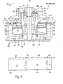
- the rotor magnet 14 can be partially demagnetized in a targeted manner in the region of the larger axial projection, as indicated in the development according to FIG. 2.
- the rotor magnetic poles are designated 51, the pole gaps 52 and the areas with weakened induction 53.
- the partial demagnetization regions 53 each end at a distance from the pole gaps. Therefore, a flawless approach speak of the sensor 49 guaranteed, while the partial demagnetization acts like a shortening of the larger projection with respect to the magnetic axial forces.
- FIG. 4 corresponds to that of FIG. 1 with the exception that an O-ring 54 is provided instead of the intermediate piece 28.
- the O-ring 54 engages in an annular groove 55 on the outer surface of the bearing support part 22. If necessary, a corresponding groove can also be provided in the stator iron.
- FIG. 5 shows a particularly flat motor 60, parts which correspond functionally to the parts of the embodiment according to FIG. 1 being provided with the same reference symbols and not being explained again in detail.
- the sound-absorbing multilayer structure consisting of the mounting flange 26, shielding plate 35, printed circuit board 36 and the interposed layers 40, 41 and openings 61 distributed in the bottom of the rotor housing 11 serve to reduce noise.
- the rotor housing 11 equipped with the openings 61 reverses the principle of a piston loudspeaker in a closed box.
- seven equidistant openings are provided.
Landscapes
- Engineering & Computer Science (AREA)
- Power Engineering (AREA)
- Physics & Mathematics (AREA)
- Electromagnetism (AREA)
- Motor Or Generator Frames (AREA)
- Brushless Motors (AREA)
- Control Of Ac Motors In General (AREA)
- Iron Core Of Rotating Electric Machines (AREA)
- Control Of Direct Current Motors (AREA)
Abstract
Description
Die Erfindung betrifft einen Elektromotor, insbesondere in Form eines kollektorlosen Gleichstrommotors, der vorzugsweise zum Antrieb von Plattenspeichern bestimmt ist, sich aber auch für andere Antriebsaufgaben, vor allem im Bürobereich, eignet, und der einen im wesentlichen zylindrischen Luftspalt zwischen Stator und Rotor hat, wobei der Stator an einem Lagerteil für die Lagerung der Rotorwelle angebracht ist.The invention relates to an electric motor, in particular in the form of a brushless DC motor, which is preferably intended for driving disk memories, but is also suitable for other drive tasks, especially in the office area, and which has an essentially cylindrical air gap between the stator and rotor, wherein the stator is attached to a bearing part for the bearing of the rotor shaft.
Die zulässigen Geräuschemissionen von Geräten, die am Arbeitsplatz im Büro stehen, werden immer weiter herabgesetzt. Insbesondere gilt dies für Arbeitsplatzrechner. In solche Rechner wird schon heute eine sehr hohe Rechner- und Speicherleistung eingebaut, und die Rechner sind in der Regel mit Plattenspeichern, insbesondere Hartplattenspeichern, und Lüftern ausgestattet. Die einzigen Komponenten, die in einem solchen Fall Geräusche emittieren, sind die Antriebsmotoren für die Plattenspeicher und Lüfter.The permissible noise emissions from devices that are in the workplace in the office are continuously being reduced. This applies in particular to workstation computers. A very high computing and storage capacity is already built into such computers today, and the computers are generally equipped with disk storage devices, in particular hard disk storage devices, and fans. The only components that emit noise in such a case are the drive motors for the disk storage and fans.
Man könnte daran denken, bei einem Plattenspeicher z.B. entweder den Motor als Ganzes weichelastisch aufzuhängen oder für die Lagerung der Rotorwelle vorgesehene Kugellager, die bekanntlich die Hauptgeräuschquelle darstellen, elastisch zu montieren. Beide Maßnahmen sind aber gerade bei einem Plattenspeicher nicht praktikabel, weil beispielsweise im ; Falle eines Hartplattenspeichers nicht wiederholbare Lageveränderungen der Rotorachse, d.h. der nicht wiederholbare Schlag, kleiner als zum Beispiel 1 µm sein müssen.One could think of, for example, in a disk storage device either suspending the motor as a whole in a flexible manner or Ball bearings intended for the bearing of the rotor shaft, which are known to be the main source of noise, must be mounted elastically. However, both measures are not practicable, particularly in the case of a disk storage, for example in the; In the case of hard disk storage, non-repeatable changes in the position of the rotor axis, ie the non-repeatable stroke, must be less than, for example, 1 µm.
Der Erfindung liegt die Aufgabe zugrunde, einen für den Antrieb von Plattenspeichern, aber auch von anderen Geräten, geeigneten Elektromotor, insbesondere einen kollektorlosen Gleichstrommotor, zu schaffen, der eine besonders niedrige Geräuschemission hat und der zugleich mit sehr kleinem nicht wiederholbarem Schlag ausgeführt werden kann.The invention has for its object to provide a suitable for driving disk storage, but also of other devices, suitable electric motor, in particular a collectorless DC motor, which has a particularly low noise emission and which can be carried out at the same time with a very small, non-repeatable stroke.
Ausgehend von einem Elektromotor der eingangs genannten Art wird diese Aufgabe erfindungsgemäß dadurch gelöst, daß der Stator mit dem Lagertragteil über eine elastische Dämpfungsanordnung verbunden ist. Bei einem solchen Aufbau werden Lagergeräusche wirkungsvoll vermindert, da in der Lagerung, beispielsweise den Kugellagern, entstehende Schallwellen nicht mehr am Stator reflektiert werden und somit an einem Hin- und Herlaufen zwischen Lagerung und Stator gehindert sind. Umgekehrt werden auch im Stator elektromagnetisch erzeugte Geräusche an einem Hin- und Herreflektieren zwischen Stator und Lagerung gehindert. Zu solchen elektromagnetisch erzeugten Geräuschen kann es insbesondere aufgrund von axialen und/oder radialen elektromagnetischen Störkräften zwischen Rotor und Stator kommen.Starting from an electric motor of the type mentioned, this object is achieved in that the stator is connected to the bearing support part via an elastic damping arrangement. With such a structure, bearing noises are effectively reduced, since sound waves generated in the bearing, for example the ball bearings, are no longer reflected on the stator and are therefore prevented from running back and forth between the bearing and the stator. Conversely, noise generated electromagnetically in the stator is prevented from being reflected back and forth between the stator and the bearing. Such electromagnetically generated noises can occur in particular due to axial and / or radial electromagnetic interference between the rotor and the stator.
Die elastische Dämpfungsanordnung ist vorzugsweise axial im Bereich der Lagerung der Rotorwelle angeordnet und axial kurz ausgebildet. Sie kann zweckmäßig eine weiche Vergußmasse zwischen dem Stator und dem Lagerteil aufweisen, welche vorteilhaft nach dem Aushärten ein mit dem Stator und/oder dem Lagertragteil formschlüssig verbundenes Zwischenstück bildet. Dieses Zwischenstück kann zweckmäßig Ringform haben. Eine solche Dämpfungsanordnung läßt sich fertigungsmäßig besonders einfach herstellen und sorgt gleichwohl für eine weitgehende Dämpfung zwischen Lagertragteil und Stator. Entsprechend einer abgewandelten Ausführungsform kann die elastische Dämpfungsanordnung auch ein oder mehrere vorgefertigte elastische Bauteile, insbesondere elastische O-Ringe, aufweisen. Für eine sichere Halterung des Stators am Lagertragteil greift vorzugsweise der O-Ring mit einem Teil seines Querschnitts in eine entsprechende Nut an den einander zugewendeten Flächen von Stator und/oder Lagertragteil ein.The elastic damping arrangement is preferably arranged axially in the region of the bearing of the rotor shaft and is axially short. It can expediently have a soft casting compound between the stator and the bearing part, which advantageously, after curing, has an intermediate piece which is positively connected to the stator and / or the bearing support part forms. This intermediate piece can usefully have a ring shape. Such a damping arrangement can be produced in a particularly simple manner in terms of production and nevertheless ensures extensive damping between the bearing support part and the stator. According to a modified embodiment, the elastic damping arrangement can also have one or more prefabricated elastic components, in particular elastic O-rings. For a secure mounting of the stator on the bearing support part, the O-ring preferably engages with a part of its cross section in a corresponding groove on the facing surfaces of the stator and / or bearing support part.
Entsprechend einem weiteren erfindungsgemäßen Lösungsvorschlag für das oben geschilderte Problem sind der Stator und das Lagertragteil im Bereich mindestens eines wesentlichen Teils ihrer einander zugewendeten Flächen durch einen Luftspalt voneinander getrennt, der sich vorzugsweise über einen großen Teil der axialen Statoreisenlänge erstreckt. Ein solcher Luftspalt führt, wie gefunden wurde, bereits allein zu einer wesentlichen Absenkung des Geräuschpegels des Elektromotors. Er kann aber vorteilhaft auch in Kombination mit der vorstehend erläuterten elastischen Dämpfungsanordnung vorgesehen werden. Vorzugsweise trennt der Luftspalt den Stator und das Lagertragteil vor allem in dem für die Geräuschübertragung kritischen Bereich, welcher der Lagerung der Rotorwelle benachbart ist.According to a further proposed solution according to the invention for the problem described above, the stator and the bearing support part are separated from one another in the region of at least a substantial part of their surfaces facing one another by an air gap which preferably extends over a large part of the axial stator iron length. Such an air gap, as has been found, alone leads to a substantial reduction in the noise level of the electric motor. However, it can advantageously also be provided in combination with the elastic damping arrangement explained above. The air gap preferably separates the stator and the bearing support part, especially in the area critical for noise transmission, which is adjacent to the bearing of the rotor shaft.
Bei kombiniertem Einsatz von elastischer Dämpfungsanordnung und dem erwähnten Luftspalt stehen der Stator und das Lagertragteil vorzugsweise im wesentlichen nur im Bereich der elastischen Dämpfungsanordnung miteinander in Verbindung, während sie im übrigen durch den Luftspalt voneinander getrennt sind.When the elastic damping arrangement and the air gap mentioned are used in combination, the stator and the bearing support part are preferably connected to one another essentially only in the region of the elastic damping arrangement, while they are otherwise separated from one another by the air gap.
Gemäß einem weiteren Merkmal der Erfindung ist die Rotorwelle in zwei Kugellagern mit jeweils unterschiedlicher Anzahl von Kugeln gelagert. Dieses Merkmal senkt gleichfalls die Geräuschemission, und es kann für sich allein oder gemeinsam mit einem oder mehreren der zuvor diskutierten erfindungsgemäßen Merkmale vorgesehen werden.According to a further feature of the invention, the rotor shaft is supported in two ball bearings, each with a different number of balls. This feature also lowers the noise emission, and it can be provided alone or together with one or more of the features of the invention discussed above.
Es sind Elektromotoren der eingangs genannten Art, insbesondere zum Antrieb von Plattenspeichern, bekannt, bei denen das Lagertragteil seinerseits mit einem sich im wesentlichen senkrecht zu der Achse der Rotorwelle erstreckenden Befestigungsflansch verbunden ist. Im Falle eines solchen Elektromotors läßt sich die vorliegend gestellte Aufgabe lösen, wenn der Befestigungsflansch einen schalldämpfenden Belag aufweist. Auch dieses Merkmal eignet sich für einen alleinigen Einsatz ebenso wie für einen Einsatz in Kombination mit einer oder mehreren der oben geschilderten Maßnahmen.Electric motors of the type mentioned at the outset, in particular for driving disk stores, are known in which the bearing support part is in turn connected to a fastening flange which extends essentially perpendicular to the axis of the rotor shaft. In the case of such an electric motor, the object set here can be achieved if the fastening flange has a sound-absorbing covering. This feature is also suitable for sole use as well as for use in combination with one or more of the measures described above.
Trägt der Befestigungsflansch, wie an sich bekannt (DE-A-31 44 629) eine Leiterplatte und/oder eine magnetische Abschirmung, ist der Befestigungsflansch in weiterer Ausgestaltung der Erfindung mit der Leiterplatte und/oder der magnetischen Abschirmung zu einem schalldämpfenden Mehrschichtkörper verbunden. Dabei kann zweckmäßig zwischen den Schichten des Mehrschichtkörpers eine weiche Vergußmasse und/oder ein elastischer Kleber vorgesehen sein. Es zeigte sich, daß so eine wesentliche Geräuschminderung selbst dann möglich ist, wenn im Interesse der Genauigkeitsanforderung für die Position der Rotorachse mit Bezug auf den Befestigungsflansch der letztere und das Lagertragteil einstückig ausgebildet sind.If, as is known per se (DE-A-31 44 629), the fastening flange carries a printed circuit board and / or a magnetic shield, the fastening flange is connected to the printed circuit board and / or the magnetic shield in a further embodiment of the invention to form a sound-absorbing multilayer body. A soft potting compound and / or an elastic adhesive can be expediently provided between the layers of the multilayer body. It was shown that such a substantial reduction in noise is possible even if, in the interest of the accuracy requirement for the position of the rotor axis with respect to the mounting flange, the latter and the bearing support part are integrally formed.
Bei einem Elektromotor, bei welchem der Rotor als Außenläuferrotor mit einem im wesentlichen becherförmigen Rotorgehäuse ausgebildet ist (vergleiche z.B. wiederum DE-A-31 44 629), führen auch im Boden des Rotorgehäuses verteilte Öffnungen zu einer merklichen Verminderung der Geräuschemission. Auch dieses Merkmal läßt sich allein oder in Kombination mit einem oder mehreren der vorerläuterten Merkmale vorsehen.In an electric motor in which the rotor is designed as an external rotor with an essentially cup-shaped rotor housing (see, for example, again DE-A-31 44 629), openings distributed in the bottom of the rotor housing also lead to a noticeable reduction in noise emissions. This feature can also be provided alone or in combination with one or more of the previously explained features.
Entsprechend einem weiteren Merkmal der Erfindung sind bei einem Elektromotor der eingangs genannten Art zur Geräuschminderung zwischen Rotor und Stator wirkende, insbesondere axiale elektromagnetische Störkräfte minimiert, was wiederum allein oder in Verbindung mit einem oder mehreren der zuvor diskutierten Merkmale geschehen kann. Zur Störkraftminimierung können die magnetischen Komponenten von Rotor und Stator symmetrisch in einer senkrecht zur Achse liegenden Symmetrieebene angeordnet sein. Dies stellt jedoch eine in der Praxis mit mechanisch konstruktiven Mitteln nicht immer gangbare Lösung dar. Insbesondere wenn im Falle eines kollektorlosen Gleichstrommotors für die von der Rotorstellung abhängige Kommutierung der Ströme in den Motorwicklungen ein oder mehrere galvanomagnetische Sensoren, beispielsweise Hall-Generatoren oder Hall-ICs benutzt werden, die im Einflußbereich des Rotormagnetfeldes liegen, wird auf der dem oder den Sensoren zugekehrten Seite eine gewisser axialer Überstand des Rotormagneten notwendig, um eine für die Ansteuerung der Sensoren ausreichende Magnetflußdichte zu gewährleisten. Auf der gegenüberliegenden Seite wird der axiale überstand dagegen zweckmäßig kleiner gehalten, um teueres Magnetmaterial und/oder axiale Baulänge einzusparen. Man kommt so zu einem permanentmagnetischen Rotor, dessen zur Achse senkrechte, magnetisch wirksame Symmetrieebene mit Bezug auf die zur Achse senkrechte Symmetrieebene des Statoreisens axial versetzt ist. Die unterschiedliche Größe der axialen Uberstände hat zur Folge, daß auf den Rotor, dessen Magnet sich magnetisch symmetrisch zu dem Statoreisen einzustellen sucht, eine Axialkraft ausgeübt wird. Diese Kraft ist im allgemeinen drehstellungsabhängig, beispielsweise weil der Luftspalt zwischen Rotor und Stator nicht überall gleiche Abmessungen hat. Dies kann dann zu den bereits weiter oben erwähnten elektromagnetisch erzeugten Geräuschen führen. Dem kann bei einer solchen unsymmetrischen Auslegung in weiterer Ausgestaltung der Erfindung dadurch begegnet werden, daß der Stator ein Endblech trägt, das zur axialen Symmetrierung des Magnetfeldes mit dem Rotormagneten zusammenwirkt und vorzugsweise mindestens einen Teil des Luftspalts im Bereich des größeren Überstandes begrenzt.According to a further feature of the invention, in an electric motor of the type mentioned at the outset, in particular axial electromagnetic interference forces acting to reduce noise between the rotor and the stator are minimized, which in turn can be done alone or in connection with one or more of the features discussed above. To minimize interference forces, the magnetic components of the rotor and stator can be arranged symmetrically in a plane of symmetry perpendicular to the axis. However, this represents a solution that is not always feasible in practice with mechanical design means. In particular, if one or more galvanomagnetic sensors, for example Hall generators or Hall ICs, for commutation of the currents in the motor windings depending on the rotor position are used that are in the area of influence of the rotor magnetic field, a certain axial projection of the rotor magnet is necessary on the side facing the sensor or sensors in order to ensure a sufficient magnetic flux density for the control of the sensors. On the other hand, the axial overhang is expediently kept smaller in order to save expensive magnetic material and / or axial length. The result is a permanent magnetic rotor whose magnetically effective plane of symmetry perpendicular to the axis is axially offset with respect to the plane of symmetry of the stator iron perpendicular to the axis. The different size of the axial projections has the result that an axial force is exerted on the rotor, the magnet of which attempts to adjust itself magnetically symmetrically to the stator iron. This force is generally dependent on the rotational position, for example because the air gap between the rotor and the stator does not have the same dimensions everywhere. This can then lead to the electromagnetically generated noises already mentioned above. This can be countered with such an asymmetrical design in a further embodiment of the invention in that the stator carries an end plate, which interacts with the rotor magnet for axial symmetry of the magnetic field and preferably delimits at least part of the air gap in the region of the larger projection.
Entsprechend einer abgewandelten Ausführungsform der Erfindung lassen sich elektromagnetisch bedingte Geräusche dadurch reduzieren, daß im Bereich des größeren axialen überstandes die Induktion im mittleren Teil der Rotormagnetpole mindestens bereichsweise schwächer gemacht wird als an den an die Pollücken angrenzenden Randbereichen der Rotormagnetpole. Auch dadurch läßt sich eine Axialkraftsymmetrierung erzwingen, während gleichzeitig ein sicheres Ansprechen der Drehstellungssensoren gewährleistet ist.According to a modified embodiment of the invention, electromagnetic noises can be reduced by making the induction in the central part of the rotor magnetic poles weaker at least in regions than in the edge regions of the rotor magnetic poles adjacent to the pole gaps in the region of the larger axial projection. Axial force symmetry can also be forced thereby, while at the same time a reliable response of the rotary position sensors is ensured.
Wesentlich ist, daß eine magnetische Symmetrierung insgesamt derart erfolgt, daß die Summe der magnetischen Axialkräfte zwischen Rotor und Stator beim fertig montierten Motor möglichst klein, vorzugsweise Null, ist.It is essential that magnetic symmetry takes place overall in such a way that the sum of the magnetic axial forces between the rotor and the stator is as small as possible, preferably zero, in the fully assembled motor.
Die Erfindung ist im folgenden anhand von bevorzugten Ausführungsbeispielen näher erläutert. In den beiliegenden Zeichnungen zeigen:
- Fig. 1 einen Schnitt durch einen erfindungsgemäß aufgebauten Antriebsmotor für einen Hartplattenspeicher,
- Fig. 2 eine Teilabwicklung des Rotormagneten des Motors nach Fig. 1,
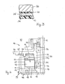
- Fig. 3 in größerem Maßstab einen Teilschnitt durch den Befestigungsflansch des Motors nach Fig. 1 mit Leiterplatte und magnetischer Abschirmung,
- Fig. 4 eine abgewandelte Ausführungsform ähnlich Fig.1 im Schnitt,
- Fig. 5 einen Schnitt durch einen Plattenspeicherantriebsmotor entsprechend einer weiter abgewandelten Ausführungsform der Erfindung, und
- Fig. 6 eine Draufsicht auf die Unterseite des Rotorgehäuses des Motors nach Fig. 5.
- 1 shows a section through an inventive drive motor for a hard disk storage,
- 2 shows a partial development of the rotor magnet of the motor according to FIG. 1,
- 3 is a partial section on a larger scale through the mounting flange of the motor of FIG. 1 with circuit board and magnetic shield,
- 4 shows a modified embodiment similar to FIG. 1 in section,
- 5 shows a section through a disk storage drive motor according to a further modified embodiment of the invention, and
- 6 shows a plan view of the underside of the rotor housing of the motor according to FIG. 5.
In Fig. 1 ist ein als kollektorloser Gleichstrommotor aufgebauter Außenläufer-Direktantriebsmotor für Festplattenspeicher veranschaulicht, der insgesamt mit 10 bezeichnet ist. Der Motor weist ein becherförmiges Rotorgehäuse 11 auf, das konzentrisch zu einer Rotorwelle 12 sitzt und mit dieser über eine Buchse 13 fest verbunden ist, die in eine Mittel--öffnung des Rotorgehäuses eingepreßt ist. In dem aus magnetisch gut leitendem Werkstoff bestehenden Rotorgehäuse 11 sind eine Mehrzahl von Permanentstücken oder ein einteiliger Permanentring 14 angebracht, der zusammen mit den Bauteilen 11 bis 13 den Rotor 15 des Motors 10 bildet. Der Permanentmagnetring 14 besteht vorzugsweise aus einer Mischung von Hartferrit, z.B. Bariumferrit, und elastischem Material. Es handelt sich also um einen sogenannten Gummimagneten. Dieser ist über der Polteilung trapezförmig oder annähernd trapezförmig bei relativ kleiner Pollücke radial magnetisiert. Das Rotorgehäuse 11 kann als Tiefziehteil hergestellt sein.1 illustrates an external rotor direct drive motor for hard disk storage, which is constructed as a collectorless DC motor and is designated overall by 10. The motor has a cup-
Zu dem Stator 16 des Motors 10 gehört insbesondere ein Wicklungskern 17, der aus dem eigentlichen Statoreisen 18, im allgemeinen in Form eines Statorblechpakets, sowie aus Endscheiben 19, 20 besteht und der eine Statorwicklung 21 trägt. Der Wicklungskern 17 ist an einem rohrförmigen Lagertragteil 22 abgestützt. Die Rotorwelle 12 ist in dem Lagertragteil.22 mit Hilfe von zwei Kugellagern 23, 24 gelagert, die sich mit ihren einander zugewendeten Stirnseiten an entsprechenden Schultern des Lagertragteils 22 abstützen und die unterschiedliche Anzahlen von Kugeln aufweisen. Eine Tellerfeder 25 legt sich gegen die Unterseite des Innenrings des Kugellagers 23 und die diesem Kugellager zugewendete Stirnseite der Buchse 13 an, wodurch die Kugellager axial gegeneinander verspannt werden. Das Lagertragteil bildet zusammen mit einem Befestigungsflansch 26 ein einstückiges Druckgußteil. Statt dessen kann das Lagertragteil auch mit Preßsitz in einer mit dem Befestigungsflansch verbundenen Nabe sitzen oder mit dem Befestigungsflansch auf andere Weise fest verbunden, Z.B. verlötet sein. Der Magnetring 14 und der Wicklungskern 17 begrenzen einen im wesentlichen zylindrischen Luftspalt 27.The
Wie aus Fig. 1 hervorgeht, ist der Stator 16 mit dem Lagertragteil 22 über eine elastische Dämpfungsanordnung verbunden, die axial oberhalb des Kugellagers 23 sitzt und aus einem ringförmigen Zwischenstück 28 aus einer weichen Vergußmasse besteht. In dem in Fig. 1 axial unterhalb des Zwischenstücks 28 liegenden Bereich sind der Stator 16 und das Lagertragteil 22 durch einen engen Luftspalt 29 voneinander getrennt. Bei der Montage des Motors 10 wird zweckmäßig zunächst in eine Rille 30 an der Mantelfläche des Lagertragteils 22 eine Raupe aus einer elastischen Vergußmasse, beispielsweise aus einem Polyurethan-Härter-Gemisch, eingebracht. Dann wird der Stator 16 auf das Lagertragteil 22 aufgeschoben, bis sich ein ringförmiger Ansatz 31 der Endscheibe 20 mit seiner Innenfläche gegen einen Abschnitt 32 der Mantelfläche des Lagertragteils 22 sowie mit seiner Stirnfläche gegen eine Schulter 33 des Lagertragteils 22 anlegt. Der Stator 16 wird mit Bezug auf die Achse der Rotorwelle 12 zentriert. Anschließend wird die Vergußmasse ausgehärtet. Das auf diese Weise entstandene elastische Zwischenstück 28 sorgt für eine formschlüssige Verbindung von Stator 16 und Lagertragteil 22, die in Verbindung mit dem Luftspalt 29 die Schallschwingungsübertragung zwischen den Bauteilen 16, 22 wirkungsvoll dämpft. Die mechanische Verbindung der Bauteile 16, 22 befindet sich bei der Ausführungsform der Fig. 1 an einer Stelle, die vom Ort der Hauptgeräuschquelle axial in Abstand liegt. Die Wand des Lagertragteils 22 kann im Bereich der Anlagezone 34 des Außenringes des Kugellagers 23 elastisch ausweichen. All dies trägt zur wesentlichen Minderung der Geräuschemission bei.As is apparent from Fig. 1, the
An der Unterseite des Befestigungsflanschs 26 befinden sich ein Abschirmblech 35 aus magnetisch gut leitendem Werkstoff und eine gedruckte Leiterplatte 36. Das Abschirmblech 35 verhindert in Verbindung mit dem Rotorgehäuse 11 und dem Kugellager 24 den Austritt von magnetischen Streufeldern in den von den Hartspeicherplattenen eingenommenen Raum 37. Auf der Leiterplatte 36 sitzen die Antriebselektronik und gegebenenfalls eine Drehzahlregelschaltung, die nicht näher veranschaulicht sind. Der beispielsweise als Aluminiumdruckguß bestehende Befestigungsflansch 26 weist Nasen 38 auf, die durch Ausnehmungen der Bauteile 35, 36 hindurchragen und auf die Federklemmen 39 zum Halten des Abschirmbleches 35 aufgesetzt sind. Zwischen den Befestigungsflansch 26 und das Abschirmblech 35 ist, wie deutlicher aus Fig. 3 hervorgeht, eine Lage 40 aus Vergußmasse, beispielsweise Polyurethan, eingebracht, während sich zwischen dem Abschirmblech 35 und der Leiterplatte 36 eine Lage 41 aus Epoxidkleber oder einem anderen schalldämpfenden Material befindet. Der Befestigungsflansch 26, das Abschirmblech 35 und die Leiterplatte 36 sind auf diese Weise zu einem schalldämpfenden Mehrschichtkörper miteinander verbunden. Es versteht sich, daß gegebenenfalls auch das Abschirmblech und die Leiterplatte ihre Plätze vertauschen können. Daneben können beide Lagen 40, 41 aus Vergußmasse, aus Kleber oder einem sonstigen Schallschwingungen dämpfenden Werkstoff bestehen.On the underside of the mounting
Der Befestigungsflansch 26 gestattet es, den Motor 10 an einer Trennwand eines Hartplattenspeichers anzubringen, die in bekannter Weise (z.B. DE-A- 31 08 204) den Raum 37 vom übrigen Geräteinneren abtrennt. Eine zur Aufnahme einer oder mehrerer Hartspeicherplatten dienende Nabe 42 ist mit dem in Fig. 1 oberen Ende der Rotorwelle 12 fest verbunden. Um das Lagersystem der Rotorwelle 12 gegenüber dem Speicherlattenaufnahmeraum abzudichten, ist im Bereich zwischen der Nabe 42 und dem Lager 24 eine Magnetflüssigkeitsdichtung 43 in das Lagertragteil 22 eingesetzt. Die Dichtung 43 besteht aus zwei Polstücken 44, 45, einem zwischen den Polstücken sitzenden Permanentmagnetring 46 und einer magnetischen Flüssigkeit, die in einen Ringspalt 47 zwischen dem Magnetring 46 und der Rotorwelle 12 eingebracht ist. An der Außenseite des Bodens des Rotorgehäuses 11 ist ein Radialgebläserad 48 befestigt, das Luft im zentralen Bereich anzieht und radial nach außen schleudert.The mounting
Entsprechend Fig. 1 ist für die Steuerung der Kommutierung des Motors 10 ein galvanomagnetischer Drestellungssensor, z.B. in Form eines Hallgenerators 49 vorgesehen, der an der Leiterplatte 36 angelötet ist und durch das Feld des Magnetringes 14 beeinflußt wird. Um den Sensor 49 sicher ansprechen zu lassen, steht der Rotormagnet 14 auf der der Leiterplatte 36 zugewendeten Seite über das Statoreisen 18 weiter axial über als an der dem Boden des Rotorgehäuses 11 zugekehrten Seite. Um dadurch hervorgerufenen axialen Störkräften entgegenzuwirken, die gleichfalls Anlaß zu Geräuschen sein können, ist auf der Seite größeren axialen überstandes ein Statorendblech 50 vorgesehen. Das Endblech 50 ragt in den Bereich des axial weiter überstehenden Magneten 14 hinein und begrenzt dort in einer vorbestimmten Teilzone den Luftspalt 27. Auf diese Weise erfolgt eine Symmetrierung des Magnetfeldes. Zusätzlich oder statt dessen kann der Rotormagnet 14 im Bereich des größeren axialen überstandes gezielt teilentmagnetisiert sein, wie dies in der Abwicklung gemäß Fig. 2 angedeutet ist. Dabei sind die Rotormagnetpole mit 51, die Pollücken mit 52 und die Bereiche mit abgeschwächter Induktion mit 53 bezeichnet. Die Teilentmagnetisierungsbereiche 53 enden jeweils in einem Abstand von den Pollücken. Daher ist ein einwandfreies Ansprechen des Sensors 49 gewährleistet, während die Teilentmagnetisierung bezüglich der magnetischen Axialkräfte wie eine Verkürzung des größeren überstandes wirkt.1, a galvanomagnetic position sensor, for example in the form of a
Die Ausführungsform gemäß Fig. 4 stimmt mit derjenigen der Fig. 1 mit der Ausnahme überein, daß anstelle des Zwischenstückes 28 ein O-Ring 54 vorgesehen ist. Der O-Ring 54 greift in eine Ringnut 55 an der Mantelfläche des Lagertragteils 22 ein. Gegebenenfalls kann eine entsprechende Nut auch in dem Statoreisen vorgesehen sein.The embodiment according to FIG. 4 corresponds to that of FIG. 1 with the exception that an O-
In Fig. 5 ist ein besonders flach aufgebauter Motor 60 dargestellt, wobei Teile, die funktionsmäßig den Teilen der Ausführungsform nach Fig. 1 entsprechen, mit gleichen Bezugszeichen versehen und nicht nochmals näher erläutert sind. Zur Geräuschminderung dienen in diesem Fall der schalldämpfende Mehrschichtaufbau aus Befestigungsflansch 26, Abschirmblech 35, Leiterplatte 36 und den zwischengefügten Lagen 40, 41 sowie im Boden des Rotorgehäuses 11 verteilte öffnungen 61. Das mit den öffnungen 61 ausgestattete Rotorgehäuse 11 stellt eine Umkehrung des Prinzips eines Kolbenlautsprechers in einer geschlossenen Box dar. Vorzugsweise sind sieben äquidistant angeordnete öffnungen vorgesehen.5 shows a particularly flat motor 60, parts which correspond functionally to the parts of the embodiment according to FIG. 1 being provided with the same reference symbols and not being explained again in detail. In this case, the sound-absorbing multilayer structure consisting of the mounting
Es versteht sich, daß die vorstehend erläuterten Schalldämpfungsmaßnahmen grundsätzlich sowohl jeweils allein als auch in beliebigen Kombinationen angewendet werden können. Statt der gezeigten Kugellager können auch Gleitlager vorgesehen werden.It goes without saying that the above-described sound attenuation measures can in principle be used both individually and in any combination. Instead of the ball bearings shown, plain bearings can also be provided.
Claims (22)
Priority Applications (2)
| Application Number | Priority Date | Filing Date | Title |
|---|---|---|---|
| EP91100691A EP0425478B2 (en) | 1983-12-28 | 1984-12-22 | External rotor motor, in particular collectorless direct-current motor |
| AT84116201T ATE66322T1 (en) | 1983-12-28 | 1984-12-22 | ELECTRIC MOTOR, IN PARTICULAR COLLECTORLESS DIRECT CURRENT MOTOR. |
Applications Claiming Priority (4)
| Application Number | Priority Date | Filing Date | Title |
|---|---|---|---|
| DE3347360A DE3347360C2 (en) | 1983-12-28 | 1983-12-28 | Brushless external rotor DC motor |
| DE3347360 | 1983-12-28 | ||
| US57018784A | 1984-01-12 | 1984-01-12 | |
| US570187 | 1990-08-20 |
Related Child Applications (2)
| Application Number | Title | Priority Date | Filing Date |
|---|---|---|---|
| EP91100691.4 Division-Into | 1991-01-21 | ||
| EP91100690.6 Division-Into | 1991-01-21 |
Publications (3)
| Publication Number | Publication Date |
|---|---|
| EP0149228A2 true EP0149228A2 (en) | 1985-07-24 |
| EP0149228A3 EP0149228A3 (en) | 1986-03-05 |
| EP0149228B1 EP0149228B1 (en) | 1991-08-14 |
Family
ID=25816866
Family Applications (2)
| Application Number | Title | Priority Date | Filing Date |
|---|---|---|---|
| EP91100691A Expired - Lifetime EP0425478B2 (en) | 1983-12-28 | 1984-12-22 | External rotor motor, in particular collectorless direct-current motor |
| EP84116201A Expired - Lifetime EP0149228B1 (en) | 1983-12-28 | 1984-12-22 | Electric motor, in particular a commutatorless direct current motor |
Family Applications Before (1)
| Application Number | Title | Priority Date | Filing Date |
|---|---|---|---|
| EP91100691A Expired - Lifetime EP0425478B2 (en) | 1983-12-28 | 1984-12-22 | External rotor motor, in particular collectorless direct-current motor |
Country Status (3)
| Country | Link |
|---|---|
| EP (2) | EP0425478B2 (en) |
| AT (1) | ATE123604T1 (en) |
| DE (2) | DE3486391D1 (en) |
Cited By (11)
| Publication number | Priority date | Publication date | Assignee | Title |
|---|---|---|---|---|
| WO1986001050A1 (en) * | 1984-07-28 | 1986-02-13 | Papst-Motoren Gmbh & Co. Kg | Axially compact direct control motor |
| EP0218915A1 (en) * | 1985-09-23 | 1987-04-22 | Siemens Aktiengesellschaft | Flanged support, especially for a laterally and axially pre-loaded bearing assembly of an electric motor with an external rotor |
| FR2600838A1 (en) * | 1986-06-27 | 1987-12-31 | Etri Sa | ELECTRIC MOTOR WITH PERFECTED BEARING |
| US4724346A (en) * | 1985-09-23 | 1988-02-09 | Siemens Aktiengesellschaft | Permanent magnet-excited external rotor motor |
| WO1988007285A1 (en) * | 1987-03-10 | 1988-09-22 | Torin Limited | Improvements relating to d.c. motors |
| WO1989005537A1 (en) * | 1987-12-10 | 1989-06-15 | Papst-Motoren Gmbh & Co Kg | Electric motor |
| EP0339765A2 (en) * | 1988-03-25 | 1989-11-02 | Magnetic Peripherals Inc. | Disk drive spindle motor |
| DE4117801A1 (en) * | 1990-06-01 | 1991-12-05 | Mitsubishi Electric Corp | Electric motor with radial flux rotor - has couple-producing stator and position or speed sensor |
| US5410201A (en) * | 1990-06-01 | 1995-04-25 | Mitsubishi Denki Kabushiki Kaisha | Electric Motor |
| US5418414A (en) * | 1993-03-31 | 1995-05-23 | U.S. Philips Corporation | Electric motor with permanent-magnet excitation |
| WO1995034115A1 (en) * | 1994-06-09 | 1995-12-14 | Digital Equipment International Ltd. | Low noise spindle motor for winchester disk drives |
Families Citing this family (3)
| Publication number | Priority date | Publication date | Assignee | Title |
|---|---|---|---|---|
| DE4335966C2 (en) * | 1993-10-21 | 1998-07-16 | Fhp Motors Gmbh | Drive device for a washing machine or similar machine with a brushless DC motor |
| JPH1198757A (en) * | 1997-09-26 | 1999-04-09 | Minebea Co Ltd | Magnetic-disk drive motor |
| DE102016015365A1 (en) * | 2016-12-16 | 2018-06-21 | Ziehl-Abegg Se | Stator / rotor for an electric motor and electric motor with a rotor and / or a stator |
Citations (5)
| Publication number | Priority date | Publication date | Assignee | Title |
|---|---|---|---|---|
| GB1310981A (en) * | 1969-05-14 | 1973-03-21 | Papst Motoren Kg | Dynamo-electric machine |
| FR2350721A1 (en) * | 1976-05-04 | 1977-12-02 | Skf Kugellagerfabriken Gmbh | EXTERNAL ROTOR ELECTRIC MOTOR |
| DE2811283A1 (en) * | 1978-03-15 | 1979-09-20 | Siemens Ag | Retention system for laminar stator packet - fixes into stator casing using steel rails with sound absorbing layers to reduce noise |
| GB2092834A (en) * | 1980-12-05 | 1982-08-18 | Papst Motoren Gmbh & Co Kg | Driving Mechanism for Magnetic Disc Drive Unit |
| FR2559319A1 (en) * | 1984-02-08 | 1985-08-09 | Mulfingen Elektrobau Ebm | ENGINE INDUCED OUTSIDE |
Family Cites Families (1)
| Publication number | Priority date | Publication date | Assignee | Title |
|---|---|---|---|---|
| DE3135385A1 (en) * | 1980-03-05 | 1983-03-17 | Papst-Motoren GmbH & Co KG, 7742 St Georgen | Disc storage unit |
-
1984
- 1984-12-22 DE DE3486391T patent/DE3486391D1/en not_active Expired - Fee Related
- 1984-12-22 EP EP91100691A patent/EP0425478B2/en not_active Expired - Lifetime
- 1984-12-22 AT AT91100691T patent/ATE123604T1/en not_active IP Right Cessation
- 1984-12-22 EP EP84116201A patent/EP0149228B1/en not_active Expired - Lifetime
- 1984-12-22 DE DE8484116201T patent/DE3484927D1/en not_active Expired - Fee Related
Patent Citations (5)
| Publication number | Priority date | Publication date | Assignee | Title |
|---|---|---|---|---|
| GB1310981A (en) * | 1969-05-14 | 1973-03-21 | Papst Motoren Kg | Dynamo-electric machine |
| FR2350721A1 (en) * | 1976-05-04 | 1977-12-02 | Skf Kugellagerfabriken Gmbh | EXTERNAL ROTOR ELECTRIC MOTOR |
| DE2811283A1 (en) * | 1978-03-15 | 1979-09-20 | Siemens Ag | Retention system for laminar stator packet - fixes into stator casing using steel rails with sound absorbing layers to reduce noise |
| GB2092834A (en) * | 1980-12-05 | 1982-08-18 | Papst Motoren Gmbh & Co Kg | Driving Mechanism for Magnetic Disc Drive Unit |
| FR2559319A1 (en) * | 1984-02-08 | 1985-08-09 | Mulfingen Elektrobau Ebm | ENGINE INDUCED OUTSIDE |
Cited By (15)
| Publication number | Priority date | Publication date | Assignee | Title |
|---|---|---|---|---|
| WO1986001050A1 (en) * | 1984-07-28 | 1986-02-13 | Papst-Motoren Gmbh & Co. Kg | Axially compact direct control motor |
| US4724346A (en) * | 1985-09-23 | 1988-02-09 | Siemens Aktiengesellschaft | Permanent magnet-excited external rotor motor |
| EP0218915A1 (en) * | 1985-09-23 | 1987-04-22 | Siemens Aktiengesellschaft | Flanged support, especially for a laterally and axially pre-loaded bearing assembly of an electric motor with an external rotor |
| US4867581A (en) * | 1985-09-23 | 1989-09-19 | Siemens Aktiengesellschaft | Bearing housing, especially for a unilaterally and axially braced external-rotor motor |
| US4783608A (en) * | 1986-06-27 | 1988-11-08 | Etudes Techniques Et Representations Industrielles E.T.R.I. | Electric motor with an improved bearing |
| EP0251896A1 (en) * | 1986-06-27 | 1988-01-07 | ETUDES TECHNIQUES ET REPRESENTATIONS INDUSTRIELLES E.T.R.I Société Anonyme | Electric motor with a modified bearing |
| FR2600838A1 (en) * | 1986-06-27 | 1987-12-31 | Etri Sa | ELECTRIC MOTOR WITH PERFECTED BEARING |
| WO1988007285A1 (en) * | 1987-03-10 | 1988-09-22 | Torin Limited | Improvements relating to d.c. motors |
| WO1989005537A1 (en) * | 1987-12-10 | 1989-06-15 | Papst-Motoren Gmbh & Co Kg | Electric motor |
| EP0339765A2 (en) * | 1988-03-25 | 1989-11-02 | Magnetic Peripherals Inc. | Disk drive spindle motor |
| EP0339765A3 (en) * | 1988-03-25 | 1991-02-06 | Magnetic Peripherals Inc. | Disk drive spindle motor |
| DE4117801A1 (en) * | 1990-06-01 | 1991-12-05 | Mitsubishi Electric Corp | Electric motor with radial flux rotor - has couple-producing stator and position or speed sensor |
| US5410201A (en) * | 1990-06-01 | 1995-04-25 | Mitsubishi Denki Kabushiki Kaisha | Electric Motor |
| US5418414A (en) * | 1993-03-31 | 1995-05-23 | U.S. Philips Corporation | Electric motor with permanent-magnet excitation |
| WO1995034115A1 (en) * | 1994-06-09 | 1995-12-14 | Digital Equipment International Ltd. | Low noise spindle motor for winchester disk drives |
Also Published As
| Publication number | Publication date |
|---|---|
| EP0425478B1 (en) | 1995-06-07 |
| DE3486391D1 (en) | 1995-07-13 |
| EP0425478B2 (en) | 1999-12-01 |
| EP0425478A2 (en) | 1991-05-02 |
| EP0149228B1 (en) | 1991-08-14 |
| EP0425478A3 (en) | 1992-10-07 |
| EP0149228A3 (en) | 1986-03-05 |
| DE3484927D1 (en) | 1991-09-19 |
| ATE123604T1 (en) | 1995-06-15 |
Similar Documents
| Publication | Publication Date | Title |
|---|---|---|
| DE3347360C2 (en) | Brushless external rotor DC motor | |
| DE3519824C2 (en) | Disk storage device | |
| EP0425478B1 (en) | External rotor motor, in particular collectorless direct-current motor | |
| DE2718428C2 (en) | ||
| DE3300574C2 (en) | ||
| EP0670621B1 (en) | Electric motor with one stator and one rotor | |
| DE3144629C2 (en) | ||
| DE3327123A1 (en) | Drive arrangement for signal-processing devices | |
| DE2919581A1 (en) | TWO-PULSE COLLECTORLESS DC MOTOR | |
| DE102005023841A1 (en) | Compensation structure for a motor | |
| DE3808222A1 (en) | CONSTRUCTION OF A BRUSHLESS FLAT-TYPE DC MOTOR | |
| DE3884749T2 (en) | Encapsulated stepper motor. | |
| DE4121428A1 (en) | SPINDLE MOTOR, ESPECIALLY FOR DISK STORAGE | |
| DE3135385A1 (en) | Disc storage unit | |
| DE3149943C2 (en) | Two-phase stepper motor | |
| DE2237250A1 (en) | ROTATION POSITION CONVERTER | |
| DE69121595T2 (en) | ROTATING ELECTROMAGNETIC SINGLE-PHASE ACTUATOR | |
| EP0164118B1 (en) | Driving arrangement with collectorless d.c. motor | |
| CH670017A5 (en) | Miniature permanent magnet electric motor - has narrow cylindrical air-gap and integral outer housing and stator of sintered metal | |
| DE3331754A1 (en) | DC motor without a commutator | |
| DE2927958C2 (en) | ||
| DE3217283C2 (en) | ||
| DE69034131T2 (en) | Electric engine | |
| DE8221291U1 (en) | COLLECTORLESS DC MOTOR FOR SIGNAL PROCESSING DEVICES | |
| EP1661229B1 (en) | Electric motor with a return ring |
Legal Events
| Date | Code | Title | Description |
|---|---|---|---|
| PUAI | Public reference made under article 153(3) epc to a published international application that has entered the european phase |
Free format text: ORIGINAL CODE: 0009012 |
|
| AK | Designated contracting states |
Designated state(s): AT BE CH DE FR GB IT LI LU NL SE |
|
| RBV | Designated contracting states (corrected) |
Designated state(s): AT CH DE FR GB IT LI |
|
| PUAL | Search report despatched |
Free format text: ORIGINAL CODE: 0009013 |
|
| AK | Designated contracting states |
Kind code of ref document: A3 Designated state(s): AT CH DE FR GB IT LI |
|
| 17P | Request for examination filed |
Effective date: 19860905 |
|
| 17Q | First examination report despatched |
Effective date: 19881124 |
|
| ITF | It: translation for a ep patent filed | ||
| GRAA | (expected) grant |
Free format text: ORIGINAL CODE: 0009210 |
|
| AK | Designated contracting states |
Kind code of ref document: B1 Designated state(s): AT CH DE FR GB IT LI |
|
| REF | Corresponds to: |
Ref document number: 66322 Country of ref document: AT Date of ref document: 19910815 Kind code of ref document: T |
|
| XX | Miscellaneous (additional remarks) |
Free format text: TEILANMELDUNG 91100690.6 EINGEREICHT AM 22/12/84. |
|
| GBT | Gb: translation of ep patent filed (gb section 77(6)(a)/1977) | ||
| REF | Corresponds to: |
Ref document number: 3484927 Country of ref document: DE Date of ref document: 19910919 |
|
| PG25 | Lapsed in a contracting state [announced via postgrant information from national office to epo] |
Ref country code: LI Effective date: 19911231 Ref country code: CH Effective date: 19911231 Ref country code: AT Effective date: 19911231 |
|
| EN | Fr: translation not filed | ||
| PG25 | Lapsed in a contracting state [announced via postgrant information from national office to epo] |
Ref country code: FR Effective date: 19920103 |
|
| PLBE | No opposition filed within time limit |
Free format text: ORIGINAL CODE: 0009261 |
|
| STAA | Information on the status of an ep patent application or granted ep patent |
Free format text: STATUS: NO OPPOSITION FILED WITHIN TIME LIMIT |
|
| 26N | No opposition filed | ||
| REG | Reference to a national code |
Ref country code: CH Ref legal event code: PL |
|
| REG | Reference to a national code |
Ref country code: FR Ref legal event code: ST |
|
| REG | Reference to a national code |
Ref country code: GB Ref legal event code: 732E |
|
| ITPR | It: changes in ownership of a european patent |
Owner name: CESSIONE;PAPST LICENSING GMBH |
|
| REG | Reference to a national code |
Ref country code: GB Ref legal event code: IF02 |
|
| PGFP | Annual fee paid to national office [announced via postgrant information from national office to epo] |
Ref country code: GB Payment date: 20021220 Year of fee payment: 19 |
|
| PGFP | Annual fee paid to national office [announced via postgrant information from national office to epo] |
Ref country code: DE Payment date: 20030224 Year of fee payment: 19 |
|
| PG25 | Lapsed in a contracting state [announced via postgrant information from national office to epo] |
Ref country code: GB Free format text: LAPSE BECAUSE OF NON-PAYMENT OF DUE FEES Effective date: 20031222 |
|
| PG25 | Lapsed in a contracting state [announced via postgrant information from national office to epo] |
Ref country code: DE Free format text: LAPSE BECAUSE OF NON-PAYMENT OF DUE FEES Effective date: 20040701 |
|
| GBPC | Gb: european patent ceased through non-payment of renewal fee |
Effective date: 20031222 |