EP0148768A2 - Klemme - Google Patents
Klemme Download PDFInfo
- Publication number
- EP0148768A2 EP0148768A2 EP85300083A EP85300083A EP0148768A2 EP 0148768 A2 EP0148768 A2 EP 0148768A2 EP 85300083 A EP85300083 A EP 85300083A EP 85300083 A EP85300083 A EP 85300083A EP 0148768 A2 EP0148768 A2 EP 0148768A2
- Authority
- EP
- European Patent Office
- Prior art keywords
- clamp
- projections
- lining
- low
- sheet
- Prior art date
- Legal status (The legal status is an assumption and is not a legal conclusion. Google has not performed a legal analysis and makes no representation as to the accuracy of the status listed.)
- Withdrawn
Links
Images

Classifications
-
- F—MECHANICAL ENGINEERING; LIGHTING; HEATING; WEAPONS; BLASTING
- F16—ENGINEERING ELEMENTS AND UNITS; GENERAL MEASURES FOR PRODUCING AND MAINTAINING EFFECTIVE FUNCTIONING OF MACHINES OR INSTALLATIONS; THERMAL INSULATION IN GENERAL
- F16B—DEVICES FOR FASTENING OR SECURING CONSTRUCTIONAL ELEMENTS OR MACHINE PARTS TOGETHER, e.g. NAILS, BOLTS, CIRCLIPS, CLAMPS, CLIPS OR WEDGES; JOINTS OR JOINTING
- F16B2/00—Friction-grip releasable fastenings
- F16B2/02—Clamps, i.e. with gripping action effected by positive means other than the inherent resistance to deformation of the material of the fastening
-
- E—FIXED CONSTRUCTIONS
- E21—EARTH OR ROCK DRILLING; MINING
- E21B—EARTH OR ROCK DRILLING; OBTAINING OIL, GAS, WATER, SOLUBLE OR MELTABLE MATERIALS OR A SLURRY OF MINERALS FROM WELLS
- E21B17/00—Drilling rods or pipes; Flexible drill strings; Kellies; Drill collars; Sucker rods; Cables; Casings; Tubings
- E21B17/01—Risers
-
- E—FIXED CONSTRUCTIONS
- E21—EARTH OR ROCK DRILLING; MINING
- E21B—EARTH OR ROCK DRILLING; OBTAINING OIL, GAS, WATER, SOLUBLE OR MELTABLE MATERIALS OR A SLURRY OF MINERALS FROM WELLS
- E21B19/00—Handling rods, casings, tubes or the like outside the borehole, e.g. in the derrick; Apparatus for feeding the rods or cables
- E21B19/002—Handling rods, casings, tubes or the like outside the borehole, e.g. in the derrick; Apparatus for feeding the rods or cables specially adapted for underwater drilling
-
- F—MECHANICAL ENGINEERING; LIGHTING; HEATING; WEAPONS; BLASTING
- F16—ENGINEERING ELEMENTS AND UNITS; GENERAL MEASURES FOR PRODUCING AND MAINTAINING EFFECTIVE FUNCTIONING OF MACHINES OR INSTALLATIONS; THERMAL INSULATION IN GENERAL
- F16L—PIPES; JOINTS OR FITTINGS FOR PIPES; SUPPORTS FOR PIPES, CABLES OR PROTECTIVE TUBING; MEANS FOR THERMAL INSULATION IN GENERAL
- F16L3/00—Supports for pipes, cables or protective tubing, e.g. hangers, holders, clamps, cleats, clips, brackets
- F16L3/16—Supports for pipes, cables or protective tubing, e.g. hangers, holders, clamps, cleats, clips, brackets with special provision allowing movement of the pipe
- F16L3/18—Supports for pipes, cables or protective tubing, e.g. hangers, holders, clamps, cleats, clips, brackets with special provision allowing movement of the pipe allowing movement in axial direction
Definitions
- This invention relates to a lining for use in structural clamp.
- a structural clamp having a body, and spaced resilient projections on the body, the projections having outermost faces of low-friction material for engaging a structure to be clamped.
- the low friction surface has a coefficient of friction of less than 0.3.
- the low friction surface is a layer of polytetrafluorethylene (PTFE) or similar material which may be bonded to the projections.
- PTFE polytetrafluorethylene
- the thickness of the layer may be from 0.1 to 5 mm, according to design and wear requirements.
- the resilience of the projections is provided by elastomer material.
- the elastomer material may be fixed to the clamp body, which may be for example of steel, by a hot bonding vulcanisation process or by a suitable adhesive.
- the projections are in the form of ribs or castellations.
- a resilient lining for use in a structural clamp, the lining having spaced projections whose outermost faces are of low-friction material for engaging a structure to be clamped.
- the various dimensions of the clamp lining are dependent on the required characteristics of the clamp design.
- the lining between the projections may vary in thickness between 4mm and 50mm.
- the height of the projections may vary between 5mm and 25mm.
- the width of the projections may vary between 10mm and 50mm and the spacing between the projections may also vary between 10mm and 50mm.
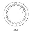
- a clamp lining for use in structural clamps comprises a moulded elastomeric sheet 1 having ribs 2 of castellated cross-section. Each rib 2 has bonded to its surface a strip 3 of PTFE having a surface coefficient of friction of less than 0.3.
- the thickness of the sheet 1 is 7 mm
- the height of the ribs 2 is 20 mm
- the width of the top of the ribs 2 is 50 mm
- the spacing between the tops of the ribs 2 is 50 mm.
- the PTFE strip 3 has the same width and length as the rib 2 and has a thickness of 3 mm.
- the elastomer material is a polychloroprene rubber CER 65 produced by Webco Industrial Rubber Limited. This rubber has a hardness of 65 IRHD units, specific capacity of 1.36, tensile strength of 17.2 N/m 2 , elongation of break 400%, tear strength of 45.5 N/mm, compression set maximum 24 hours at 70°C of 15%, abrasion resistance Akron of 0.3g/1000 revs, ozone resistance in pphm at 40°C at 20% elongation for 70 hours no cracking, sea water resistance maximum volume swell 3.5% at 70°C for 70 days immersion.
- a castellated sheet for use in the clamp lining is made by cutting a sheet of PTFE to the required castellation length and width, the sheet being etched on one surface. The etched surface is then washed with methanol and one coat of a proprietary primer is applied and allowed to dry. A proprietary bonding agent is then applied to the primed and etched surface and allowed to dry, and the strips are laid with the etched surface uppermost along the base of a mould shaped as the finished castellated sheet.
- Uncured CER 65 rubber sheet is placed into the mould on top of the PTFE, the mould is closed and a pressure of 200 tonnes applied at a temperature of 150-180°C. This causes the rubber to become flowable and it is squeezed into the castellations in the mould. The applied heat causes crosslinking between the PTFE and the rubber through the bonding agent, and results in the rubber becoming vulcanised.
- the moulded lining in the form of castellated sheet is then removed from the mould and allowed to cool.
- the prepared clamp lining sheet is then ready to be applied to the clamp surface by one of two bonding techniques.
- the first of these is the hot bond.
- the steel clamp is pre-heated to 90°C to dry its surface and is then shotblasted to SA 3.
- a proprietary primer is applied and allowed to dry.
- a bonding agent is then applied and again allowed to dry.
- a solution of the polychloroprene rubber in toluene is then prepared and brush applied to the clamp surface to render it tacky.
- the bottom face of the castellated sheet is then buffed and a coat of bonding agent is applied and allowed to dry.
- a calendered sheet of uncured polychloroprene rubber 1-2 mm thick is then provided and its surface is wiped with toluene and pre-heated to 50-70°C.
- the calendered sheet is then applied to the clamp surface, and rolled and "stitched" to exclude air.
- the outer face of the applied calendered sheet is then washed with toluene to render it tacky.
- the castellated sheet is then applied and rolled and "stitched" to exclude air.
- the lined clamp is then closed around a central mandrel to consolidate the lining, this being particularly useful on small diameter clamps.
- the clamp is then pressed in an autoclave at 60 psi steam at 153 o C for 1.5-2 hours, and then allowed to cool.
- the second bonding technique is the cold bond.
- the clamp lining is applied to the clamp using a proprietary adhesive system. This method may be used either in the factory or during site work applications. A summary of this technique will now be described.
- the metalwork is shotblasted and has primer and bonding agents applied as in the hot bond technique.
- An adhesive solution is applied to both the elastomer sheet and the clamp.
- the elastomer sheet is then applied to the clamp and rolled to exclude air.
- the bond between the elastomer and the clamp is achieved by means of an accelerated chemically activated cure in the adhesive system with ultimate bond strength being reached in 14-28 days depending on ambient temperature. In either case the ribs can be made to run vertically or horizontally in the clamp.
- the clamp can then be used to join various parts of an offshore platform structure.
- the ribbed low friction clamp liner provides a number of benefits.
- the low coefficient of friction between the clamp liner and the structure allows easy slippage of the structure through the clamping system in response to wave loading, temperature differentials and the like.
- the elastomer material absorbs some of the wave loadings and allows positive location.
- the liner accommodates some eccentricity between the clamp and the structure, and the low friction surface allows slip to take place with the different coatings that may be applied to the structure.
- a vertically ribbed clamp liner allows positive water drainage and so reduces the risk of crevice corrosion.
- the elastomer sheet may alternatively be selected, for example, from the following: Modifications and improvements may be made without departing from the scope of the invention.
Landscapes
- Engineering & Computer Science (AREA)
- Geology (AREA)
- Mechanical Engineering (AREA)
- Life Sciences & Earth Sciences (AREA)
- General Engineering & Computer Science (AREA)
- Mining & Mineral Resources (AREA)
- General Life Sciences & Earth Sciences (AREA)
- Fluid Mechanics (AREA)
- Physics & Mathematics (AREA)
- Geochemistry & Mineralogy (AREA)
- Environmental & Geological Engineering (AREA)
- Gripping Jigs, Holding Jigs, And Positioning Jigs (AREA)
- Wire Bonding (AREA)
- Earth Drilling (AREA)
- Clamps And Clips (AREA)
Applications Claiming Priority (2)
| Application Number | Priority Date | Filing Date | Title |
|---|---|---|---|
| GB8400249 | 1984-01-06 | ||
| GB848400249A GB8400249D0 (en) | 1984-01-06 | 1984-01-06 | Clamp lining |
Publications (2)
| Publication Number | Publication Date |
|---|---|
| EP0148768A2 true EP0148768A2 (de) | 1985-07-17 |
| EP0148768A3 EP0148768A3 (de) | 1985-11-13 |
Family
ID=10554612
Family Applications (1)
| Application Number | Title | Priority Date | Filing Date |
|---|---|---|---|
| EP85300083A Withdrawn EP0148768A3 (de) | 1984-01-06 | 1985-01-07 | Klemme |
Country Status (3)
| Country | Link |
|---|---|
| EP (1) | EP0148768A3 (de) |
| GB (1) | GB8400249D0 (de) |
| NO (1) | NO850060L (de) |
Cited By (4)
| Publication number | Priority date | Publication date | Assignee | Title |
|---|---|---|---|---|
| EP0413883A1 (de) * | 1989-08-25 | 1991-02-27 | POPPE + CO. GIESSENER GUMMIWARENFABRIK GMBH & CO. KG | Einlage für eine Rohrschelle |
| EP0667474A1 (de) * | 1994-02-10 | 1995-08-16 | HILTI Aktiengesellschaft | Rohrschelle mit elastischer Einlage |
| AT502513B1 (de) * | 2005-09-29 | 2007-04-15 | Semperit Ag Holding | Einlage für eine rohrschelle |
| WO2014193596A1 (en) * | 2013-05-01 | 2014-12-04 | Lord Corporation | Support liner |
Family Cites Families (6)
| Publication number | Priority date | Publication date | Assignee | Title |
|---|---|---|---|---|
| US3684223A (en) * | 1970-10-20 | 1972-08-15 | Duane D Logsdon | Pipe clamp |
| US3716896A (en) * | 1971-10-28 | 1973-02-20 | Phillips Petroleum Co | Eccentrically locking apparatus holder |
| CH571676A5 (en) * | 1973-11-02 | 1976-01-15 | Lafranco Charles | Pipe support with base plate and annular clamp - for hot and cold water pipes of urban systems in underground conduits |
| US4040883A (en) * | 1974-10-01 | 1977-08-09 | Textron, Inc. | Method of making a low-friction fabric bearing |
| GB1594535A (en) * | 1978-05-16 | 1981-07-30 | Sub Sea Int | Construction and installation of marine risers |
| US4198179A (en) * | 1978-08-11 | 1980-04-15 | The Offshore Company | Production riser |
-
1984
- 1984-01-06 GB GB848400249A patent/GB8400249D0/en active Pending
-
1985
- 1985-01-07 NO NO850060A patent/NO850060L/no unknown
- 1985-01-07 EP EP85300083A patent/EP0148768A3/de not_active Withdrawn
Cited By (5)
| Publication number | Priority date | Publication date | Assignee | Title |
|---|---|---|---|---|
| EP0413883A1 (de) * | 1989-08-25 | 1991-02-27 | POPPE + CO. GIESSENER GUMMIWARENFABRIK GMBH & CO. KG | Einlage für eine Rohrschelle |
| EP0667474A1 (de) * | 1994-02-10 | 1995-08-16 | HILTI Aktiengesellschaft | Rohrschelle mit elastischer Einlage |
| AT502513B1 (de) * | 2005-09-29 | 2007-04-15 | Semperit Ag Holding | Einlage für eine rohrschelle |
| EP1770323A3 (de) * | 2005-09-29 | 2007-04-25 | Semperit Aktiengesellschaft Holding | Einlage für eine Rohrschelle |
| WO2014193596A1 (en) * | 2013-05-01 | 2014-12-04 | Lord Corporation | Support liner |
Also Published As
| Publication number | Publication date |
|---|---|
| GB8400249D0 (en) | 1984-02-08 |
| NO850060L (no) | 1985-07-08 |
| EP0148768A3 (de) | 1985-11-13 |
Similar Documents
| Publication | Publication Date | Title |
|---|---|---|
| EP0112706B1 (de) | Isoliertes Rohr | |
| US3349418A (en) | Low friction structural bearing | |
| US6532708B1 (en) | Expansion and seismic joint covers | |
| CA2434109C (en) | Damping of conductor tubes | |
| CN111315956A (zh) | 材料 | |
| GB2393426A (en) | Underwater enclosure apparatus | |
| EP0185661B1 (de) | Wärmegedämpfte strukturen für rohrleitungen für niedrigtemperaturen oder kryogenieleitungen | |
| JPH01307597A (ja) | 粘着材層を含む積層ライニングを具えるラインパイプおよびその施工方法 | |
| KR102097567B1 (ko) | 소음 및 미끄럼 방지용 신축이음장치 | |
| EP0992719B1 (de) | Füllmaterial für spiralförmige Dichtung und spiralförmige Dichtung | |
| CN212074365U (zh) | 一种船舶建造用可调节式支撑块 | |
| US1652703A (en) | Corrugated-metal culvert | |
| US6406184B2 (en) | Partial arc bearing slab | |
| GB2166065A (en) | Insulated pipeline | |
| NO850060L (no) | Klemme | |
| Odru et al. | Composite riser and export line systems for deep offshore applications | |
| EP0840868B1 (de) | Rohrbeschichtung und rohr mit dieser beschichtung | |
| EP1140491B1 (de) | In-situ produzierte rohrformteile aus chemisch vernetztem kompostmaterial | |
| WO2017109581A1 (en) | Pipe tensioner pad | |
| JPS63151796A (ja) | 液体封入クツシヨン材 | |
| AU748072B2 (en) | Bearing slab and method of making the same | |
| US451008A (en) | Packing | |
| JP2561204B2 (ja) | 浮桟橋の外面被覆鋼管杭による支持構造 | |
| JPS59166796A (ja) | 断熱パイプライン | |
| Stevenson | Fatigue life determinations of rubber springs |
Legal Events
| Date | Code | Title | Description |
|---|---|---|---|
| PUAI | Public reference made under article 153(3) epc to a published international application that has entered the european phase |
Free format text: ORIGINAL CODE: 0009012 |
|
| AK | Designated contracting states |
Designated state(s): AT BE CH DE FR GB IT LI LU NL SE |
|
| PUAL | Search report despatched |
Free format text: ORIGINAL CODE: 0009013 |
|
| RBV | Designated contracting states (corrected) |
Designated state(s): FR GB IT NL |
|
| AK | Designated contracting states |
Designated state(s): FR GB IT NL |
|
| 17P | Request for examination filed |
Effective date: 19860506 |
|
| 17Q | First examination report despatched |
Effective date: 19870807 |
|
| STAA | Information on the status of an ep patent application or granted ep patent |
Free format text: STATUS: THE APPLICATION IS DEEMED TO BE WITHDRAWN |
|
| 18D | Application deemed to be withdrawn |
Effective date: 19890324 |
|
| RIN1 | Information on inventor provided before grant (corrected) |
Inventor name: WEBSTER, GEORGE ANDREW |