EP0148561B1 - Control device with a rotary control knob - Google Patents
Control device with a rotary control knob Download PDFInfo
- Publication number
- EP0148561B1 EP0148561B1 EP19840307136 EP84307136A EP0148561B1 EP 0148561 B1 EP0148561 B1 EP 0148561B1 EP 19840307136 EP19840307136 EP 19840307136 EP 84307136 A EP84307136 A EP 84307136A EP 0148561 B1 EP0148561 B1 EP 0148561B1
- Authority
- EP
- European Patent Office
- Prior art keywords
- knob
- housing
- control device
- circumferential edge
- control
- Prior art date
- Legal status (The legal status is an assumption and is not a legal conclusion. Google has not performed a legal analysis and makes no representation as to the accuracy of the status listed.)
- Expired
Links
- 230000002452 interceptive effect Effects 0.000 claims description 4
- 210000003811 finger Anatomy 0.000 description 7
- 238000004033 diameter control Methods 0.000 description 2
- 210000005224 forefinger Anatomy 0.000 description 2
- 210000003813 thumb Anatomy 0.000 description 2
- 238000010276 construction Methods 0.000 description 1
Images


Classifications
-
- G—PHYSICS
- G05—CONTROLLING; REGULATING
- G05G—CONTROL DEVICES OR SYSTEMS INSOFAR AS CHARACTERISED BY MECHANICAL FEATURES ONLY
- G05G1/00—Controlling members, e.g. knobs or handles; Assemblies or arrangements thereof; Indicating position of controlling members
- G05G1/08—Controlling members for hand actuation by rotary movement, e.g. hand wheels
Definitions
- This invention relates to a control device with at least one rotary control knob, and has particular though not exclusive application to the type of control device known as a valuator which is used for entering scaler values into an interactive graphics terminal.
- US-A-1 597 067 discloses control knobs from the technical field of radio receivers. Some of these knobs include a small-diameter control section and a large diameter control section; it is intended that the small section be used for coarse adjustment of the knob's angular position and the large section be used for fine adjustment.
- DE-A-2 615 470 discloses a control knob operable by a key inserted into two depressions in its top. It includes a concave tapering section which is included to make the knob difficult to operate without the key, for security reasons.
- the present invention provides a control device comprising a housing with at least one externally circularly symmetrical control knob mounted on the housing such that it may rotate about its axis of symmetry, the knob having a circumferential edge and an external axial projection whose tip has a diameter substantially less than that of the circumferential edge, the tip and the edge providing two control areas at distinct first and second radii which may be contacted by an operator's finger, characterised in that the circumferential edge of the knob is substantially fully recessed into a surface of the housing, a minor part of the circumferential edge is exposed at an edge of the housing, and the external surface of the knob slopes continuously outwardly over a major part of the distance between the tip of the axial projection and the circumferential edge to provide a third control area for contact with an operator's finger, providing a variable gear ratio between the finger and the knob.
- the sloping surface is concave and extends continuously from the tip to the circumferential edge, and the knob is recessed to substantially the full depth of the circumferential edge.
- the control device is a valuator for an interactive graphics terminal and includes a plurality of the said knobs recessed into a common surface of the housing and disposed along each of two opposite parallel sides of the housing, a minor portion of the circumferential edge of each knob being exposed at the relevant side of the housing.
- the housing includes an arcuate buffer projection immediately on the opposite axial side of each knob to the sloping surface, the projection being concentric with and of slightly greater diameter than the circumferential edge.
- knob may be rotated in the conventional manner by grasping the tip between the thumb and forefinger to permit fine setting of the knob.
- the knob may also be rapidly rotated for coarse setting by flicking the exposed edge with the finger, especially if the knob is mounted with low friction, although gentle manipulation of the exposed edge will also permit fine setting.
- the knob may be rotated by running the length of the finger along the sloping surface, and this may be done rapidly for coarse setting or slowly for fine setting of the knob. Also, the position of the finger up or down the slope varies the effective "gear" ratio between the finger and the knob.
- the invention provides a construction of control device whose control knob(s) are readily accessible by the user from a variety of positions and orientations of the device.
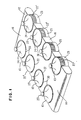
- the valuator comprises a generally rectangular housing 10 including a base 11 and a cover 12 fixed to the base in any suitable manner (not shown).
- a plurality of control knobs 13 are set into respective circular recesses 30 in the top surface 14 of the housing cover 12, the knobs 13 being disposed four along each of the two opposite parallel sides 15, 16 of the housing.
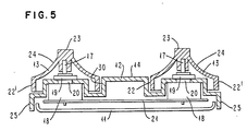
- Each knob 13 is circularly symmetric, at least externally, and is mounted for rotation about its axis of symmetry on the spindles 17 of respective potentiometers 18, Figures 4 and 5.
- the potentiometers 18 are mounted on the underside of the cover 12 with their spindles 17 projecting through the cover 12, the potentiometers being secured in place in conventional manner by nuts 19 which engage threaded collars 20 of the potentiometers. It is to be understood that the cross-section of Figure 4 is shown in a state of partial disassembly in order to illustrate these details.
- the undersides of the potentiometers 18 are fixed to a printed circuit board 21, the latter providing the electrical connections from the potentiometers to an external cable (not shown). Details of the electrical circuitry are not shown nor described since these may be entirely conventional and not relevant to the present invention which is solely concerned with the physical structure.
- Each knob 13 has a circumferential edge 22, and is recessed into the top surface 14 of the housing 10 substantially to the full depth of the edge 22. However, a minor part 22' of the edge 22 of each knob is exposed at the side 15 on 16 of the housing.
- Each knob further includes an external projection which projects axially above the surface 14, the projection terminating in a tip 23 whose diameter is substantially less than that of the circumferential edge 22. Both the tip 23 and the edge 22 are knurled as indicated in the figures.
- each knob 13 has an external concave surface 24 which slopes downwardly and outwardly continuously from the tip 23 to the edge 22. As mentioned above, it is the exposed edge portion 22', the tip 23 and the sloping surface 24 which permit the three different modes of manual rotation of each knob 13.
- the valuator may be placed flat on a working surface or, if desired, it may be stood on one end inclined against a stand.
- each exposed portion 22' is guarded by a respective arcuate buffer 25 which projects from the side 15 or 16 of the housing cover 12 immediately below the knob.
- the outer surface of each arcuate buffer 25 is concentric with the circumferential edge 22 of the knob 13 but has a slightly greater diameter than the edge 22; thus the buffer 25 projects slightly beyond the exposed edge portion 22' to protect the latter against knocks.
- the invention is not limited in its application to graphics valuators as described above, but has general applicability to control devices having one or more rotary control knobs, for example hi-fi equipment.
- the cross-sectional shape of the sloping surface 24 may be varied from that shown; thus it may be more or less curved as desired in a particular design of knob, and it need not necessarily extend substantially the full distance from the tip 23 to the edge 22 as shown.
- an annular part of the external surface of the knob adjacent the edge 22 could be flat so that the sloping surface 24 begins some distance in from the edge 22, or a part of the external surface of the knob adjacent the tip 23 could be cylindrical with the outwardly sloping surface 24 beginning only some distance below the tip.
Landscapes
- Physics & Mathematics (AREA)
- General Physics & Mathematics (AREA)
- Engineering & Computer Science (AREA)
- Automation & Control Theory (AREA)
- Mechanical Control Devices (AREA)
- Details Of Resistors (AREA)
- Adjustable Resistors (AREA)
- Rotary Switch, Piano Key Switch, And Lever Switch (AREA)
- Input From Keyboards Or The Like (AREA)
Applications Claiming Priority (2)
| Application Number | Priority Date | Filing Date | Title |
|---|---|---|---|
| US54680883A | 1983-10-31 | 1983-10-31 | |
| US546808 | 1983-10-31 |
Publications (3)
| Publication Number | Publication Date |
|---|---|
| EP0148561A2 EP0148561A2 (en) | 1985-07-17 |
| EP0148561A3 EP0148561A3 (en) | 1985-10-02 |
| EP0148561B1 true EP0148561B1 (en) | 1989-04-12 |
Family
ID=24182101
Family Applications (1)
| Application Number | Title | Priority Date | Filing Date |
|---|---|---|---|
| EP19840307136 Expired EP0148561B1 (en) | 1983-10-31 | 1984-10-17 | Control device with a rotary control knob |
Country Status (3)
| Country | Link |
|---|---|
| EP (1) | EP0148561B1 (enExample) |
| JP (1) | JPS60156125A (enExample) |
| DE (1) | DE3477701D1 (enExample) |
Families Citing this family (3)
| Publication number | Priority date | Publication date | Assignee | Title |
|---|---|---|---|---|
| JPS6219260A (ja) * | 1985-07-17 | 1987-01-28 | Junko Ishizu | 建設工事の掘削士、汚泥選別リサイクル方法およびその装置 |
| DE19941960A1 (de) * | 1999-09-03 | 2001-03-08 | Volkswagen Ag | Multifunktions-Bedienelement |
| JP2003045293A (ja) * | 2001-05-21 | 2003-02-14 | Sony Corp | 操作装置 |
Family Cites Families (5)
| Publication number | Priority date | Publication date | Assignee | Title |
|---|---|---|---|---|
| US1597067A (en) * | 1924-12-17 | 1926-08-24 | John A Dienner | Control means for shafts and the like |
| US3385944A (en) * | 1966-09-12 | 1968-05-28 | Hubbell Inc Harvey | Electric illuminating light dimmer control unit |
| DE2615470A1 (de) * | 1976-04-09 | 1977-10-20 | Miele & Cie | Wahlschalter fuer wasch- und spuelmaschinen o.dgl. |
| JPS5642731U (enExample) * | 1979-09-08 | 1981-04-18 | ||
| JPS6126968Y2 (enExample) * | 1980-07-01 | 1986-08-12 |
-
1984
- 1984-09-28 JP JP59202165A patent/JPS60156125A/ja active Granted
- 1984-10-17 EP EP19840307136 patent/EP0148561B1/en not_active Expired
- 1984-10-17 DE DE8484307136T patent/DE3477701D1/de not_active Expired
Also Published As
| Publication number | Publication date |
|---|---|
| JPS60156125A (ja) | 1985-08-16 |
| JPH0145082B2 (enExample) | 1989-10-02 |
| DE3477701D1 (en) | 1989-05-18 |
| EP0148561A2 (en) | 1985-07-17 |
| EP0148561A3 (en) | 1985-10-02 |
Similar Documents
| Publication | Publication Date | Title |
|---|---|---|
| US5808602A (en) | Rotary cursor positioning apparatus | |
| US6075518A (en) | Rotational X-axis pointing device | |
| CA1310772C (en) | Touch controlled zoom of waveform displays | |
| US4739128A (en) | Thumb-controlled, hand-held joystick | |
| CA1144965A (en) | Keyboard type switch comprising flexible printed circuit substrate | |
| US5489922A (en) | Hand worn remote computer mouse | |
| KR920016960A (ko) | 대상물의 상호작용 취급장치 | |
| EP1755319A3 (en) | User interface with auditory feedback for hand-held device | |
| EP0390041A3 (en) | Remote-control apparatus for electronics apparatus | |
| US4581609A (en) | X-Y position input device for display system | |
| EP0148561B1 (en) | Control device with a rotary control knob | |
| US4748861A (en) | Electronic display measuring device | |
| US5760766A (en) | Pointing device with relocatable cable | |
| KR20010049151A (ko) | 접속 장치 | |
| US20150325392A1 (en) | Operating switch | |
| US5990871A (en) | Ergonomic pointing device | |
| US20020066652A1 (en) | Multi-directional ball switch and operation method thereof | |
| KR100392130B1 (ko) | 위상 천이 범위의 선택이 가능한 이상기 | |
| EP1262853A1 (en) | Input device | |
| US4232207A (en) | Rotary switch assembly | |
| US5248960A (en) | Signal generating/position controlling system | |
| JPH0714475A (ja) | 多方向入力装置 | |
| US5784688A (en) | Portable radio communication device with a rotary control knob assembly | |
| JPS645786Y2 (enExample) | ||
| EP1280172A1 (en) | Selector switch, especially a four-or multi-position switch |
Legal Events
| Date | Code | Title | Description |
|---|---|---|---|
| PUAI | Public reference made under article 153(3) epc to a published international application that has entered the european phase |
Free format text: ORIGINAL CODE: 0009012 |
|
| 17P | Request for examination filed |
Effective date: 19841123 |
|
| AK | Designated contracting states |
Designated state(s): DE FR GB |
|
| PUAL | Search report despatched |
Free format text: ORIGINAL CODE: 0009013 |
|
| AK | Designated contracting states |
Designated state(s): DE FR GB |
|
| 17Q | First examination report despatched |
Effective date: 19870518 |
|
| GRAA | (expected) grant |
Free format text: ORIGINAL CODE: 0009210 |
|
| AK | Designated contracting states |
Kind code of ref document: B1 Designated state(s): DE FR GB |
|
| REF | Corresponds to: |
Ref document number: 3477701 Country of ref document: DE Date of ref document: 19890518 |
|
| ET | Fr: translation filed | ||
| PLBE | No opposition filed within time limit |
Free format text: ORIGINAL CODE: 0009261 |
|
| STAA | Information on the status of an ep patent application or granted ep patent |
Free format text: STATUS: NO OPPOSITION FILED WITHIN TIME LIMIT |
|
| 26N | No opposition filed | ||
| PGFP | Annual fee paid to national office [announced via postgrant information from national office to epo] |
Ref country code: GB Payment date: 19910923 Year of fee payment: 8 |
|
| PGFP | Annual fee paid to national office [announced via postgrant information from national office to epo] |
Ref country code: FR Payment date: 19911001 Year of fee payment: 8 |
|
| PGFP | Annual fee paid to national office [announced via postgrant information from national office to epo] |
Ref country code: DE Payment date: 19911102 Year of fee payment: 8 |
|
| PG25 | Lapsed in a contracting state [announced via postgrant information from national office to epo] |
Ref country code: GB Effective date: 19921017 |
|
| GBPC | Gb: european patent ceased through non-payment of renewal fee |
Effective date: 19921017 |
|
| PG25 | Lapsed in a contracting state [announced via postgrant information from national office to epo] |
Ref country code: FR Effective date: 19930630 |
|
| PG25 | Lapsed in a contracting state [announced via postgrant information from national office to epo] |
Ref country code: DE Effective date: 19930701 |
|
| REG | Reference to a national code |
Ref country code: FR Ref legal event code: ST |