EP0148101B1 - Procédé et appareil pour le réglage d'un compresseur centrifuge - Google Patents
Procédé et appareil pour le réglage d'un compresseur centrifuge Download PDFInfo
- Publication number
- EP0148101B1 EP0148101B1 EP84630190A EP84630190A EP0148101B1 EP 0148101 B1 EP0148101 B1 EP 0148101B1 EP 84630190 A EP84630190 A EP 84630190A EP 84630190 A EP84630190 A EP 84630190A EP 0148101 B1 EP0148101 B1 EP 0148101B1
- Authority
- EP
- European Patent Office
- Prior art keywords
- compressor
- diffuser
- flow
- wall
- width
- Prior art date
- Legal status (The legal status is an assumption and is not a legal conclusion. Google has not performed a legal analysis and makes no representation as to the accuracy of the status listed.)
- Expired - Lifetime
Links
Images


Classifications
-
- F—MECHANICAL ENGINEERING; LIGHTING; HEATING; WEAPONS; BLASTING
- F04—POSITIVE - DISPLACEMENT MACHINES FOR LIQUIDS; PUMPS FOR LIQUIDS OR ELASTIC FLUIDS
- F04D—NON-POSITIVE-DISPLACEMENT PUMPS
- F04D27/00—Control, e.g. regulation, of pumps, pumping installations or pumping systems specially adapted for elastic fluids
- F04D27/02—Surge control
- F04D27/0246—Surge control by varying geometry within the pumps, e.g. by adjusting vanes
-
- F—MECHANICAL ENGINEERING; LIGHTING; HEATING; WEAPONS; BLASTING
- F04—POSITIVE - DISPLACEMENT MACHINES FOR LIQUIDS; PUMPS FOR LIQUIDS OR ELASTIC FLUIDS
- F04D—NON-POSITIVE-DISPLACEMENT PUMPS
- F04D29/00—Details, component parts, or accessories
- F04D29/40—Casings; Connections of working fluid
- F04D29/42—Casings; Connections of working fluid for radial or helico-centrifugal pumps
- F04D29/44—Fluid-guiding means, e.g. diffusers
- F04D29/46—Fluid-guiding means, e.g. diffusers adjustable
- F04D29/462—Fluid-guiding means, e.g. diffusers adjustable especially adapted for elastic fluid pumps
- F04D29/464—Fluid-guiding means, e.g. diffusers adjustable especially adapted for elastic fluid pumps adjusting flow cross-section, otherwise than by using adjustable stator blades
-
- F—MECHANICAL ENGINEERING; LIGHTING; HEATING; WEAPONS; BLASTING
- F25—REFRIGERATION OR COOLING; COMBINED HEATING AND REFRIGERATION SYSTEMS; HEAT PUMP SYSTEMS; MANUFACTURE OR STORAGE OF ICE; LIQUEFACTION SOLIDIFICATION OF GASES
- F25B—REFRIGERATION MACHINES, PLANTS OR SYSTEMS; COMBINED HEATING AND REFRIGERATION SYSTEMS; HEAT PUMP SYSTEMS
- F25B1/00—Compression machines, plants or systems with non-reversible cycle
- F25B1/04—Compression machines, plants or systems with non-reversible cycle with compressor of rotary type
- F25B1/053—Compression machines, plants or systems with non-reversible cycle with compressor of rotary type of turbine type
-
- F—MECHANICAL ENGINEERING; LIGHTING; HEATING; WEAPONS; BLASTING
- F05—INDEXING SCHEMES RELATING TO ENGINES OR PUMPS IN VARIOUS SUBCLASSES OF CLASSES F01-F04
- F05D—INDEXING SCHEME FOR ASPECTS RELATING TO NON-POSITIVE-DISPLACEMENT MACHINES OR ENGINES, GAS-TURBINES OR JET-PROPULSION PLANTS
- F05D2250/00—Geometry
- F05D2250/50—Inlet or outlet
- F05D2250/52—Outlet
Definitions
- This invention relates to a centrifugal compressor and, in particular, to controlling the operation of a motor driven centrifugal compressor of the type used in refrigeration systems.
- variable speed compressors wherein the speed of the impeller is varied to allow for changes in flow rates have been used with some success in the art.
- These variable speed machines are very complex and thus expensive to build and operate. As a consequence they have not found wide general acceptance in the art and, in particular, the refrigeration industry.
- US-A-3 251 539 discloses a method of controlling a motor driven centrifugal compressor as well as an apparatus for preventing surge of such a compressor in accordance with the preamble of claims 1 and 8.
- variable width vaned diffuser contains a movable wall that can be selectively positioned in regard to a fixed wall to control the flow of refrigerant there between.
- a centrifugal compressor employing this movable wall feature is disclosed in EP-A-0 134 748 falling under article 54(3) EPC.
- the inlet guide vanes of that compressor are used in a conventional manner to regulate the mass flow of refrigerant through the machine while the diffuser wall positioned is varied to prevent surging. No attempt is made, however, to correlate the inlet guide vane positioning with diffuser wall positioning. It has been found through tests, however, that although the variable wall vaned diffuser approach can improve both the surge margin and overall efficiency of the compressor, an arbitrary schedule of diffuser width versus guide vane angle results in relatively poor efficiency at the lower flow ranges.
- the object of this invention to improve centrifugal compressors used in refrigeration systems and to extend the effective operating range of a centrifugal compressor.
- the efficiency . of a centrifugal compressor should thereby be optimized over a wide operating range without encountering surge.
- the efficiency of a centrifugal compressor should also be improved along a specific load line.
- a refrigeration system generally referenced 10 for chilling a liquid within an evaporator heat exchanger 11.
- the substance to be chilled is circulated through the evaporator unit via a flow circuit 12 whereupon heat energy from the circulated substance is absorbed by the refrigerant thereby cooling the substance.
- Refrigerant vapors developed in the evaporator are drawn off by means of a centrifugal compressor, generally depicted at 15, which serves to pump the refrigerant to a higher temperature and pressure.
- Slightly super-heated vapor leaving the compressor is passed through a condenser heat exchanger 18 where the superheat and latent heat is removed by cooling water passing through a flow circuit 19.
- the refrigerant leaving the condenser is flashed to a lower temperature by means of an expansion valve 20 before being passed to the inlet of the evaporator unit thereby completing the refrigeration loop.
- the compressor 15 utilized in the present system is basically a single-stage machine, however, it should be obvious that multiple-stages may be utilized in the practice of the present invention without departing from the teachings contained herein.
- the compressor as shown in Fig. 2, includes an axially aligned inlet 23 that directs incoming refrigerant into a rotating impeller wheel assembly 24 of conventional design through a series of adjustable inlet guide vanes 25-25.
- the impeller wheel includes a central hub 26 supporting a plurality of blades 27-27 that cooperate to form passages 28-28 through the rotating assembly. Refrigerant moving through the blade passages is turned radially into a diffuser section generally referenced 30.
- the diffuser section surrounds the impeller wheel and serves to direct refrigerant into a toroidal-shaped volute or collector 31. Under the combined action of the diffuser and the volume, kinetic energy stored in the refrigerant is converted into static pressure.
- the hub 34 of the impeller wheel is connected to a drive shaft 35 which, in turn, is coupled to an electrical drive motor 36 (Fig. 1), As is typical in this type of application, the motor is adapted to drive the impeller at a constant operating speed.
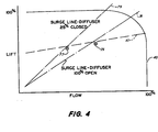
- a compressor map such as the map shown in Fig. 4 can be developed for the compressor 15 wherein lift is plotted against flow.
- the curve designated 40 represents the outer envelope of the compressor while dotted line 41 is a typical load line describing the machines operating characteristics for various inlet guide vane settings.
- a pulley and cable mechanism 43 uniformly adjusts the position of each of the vanes in response to a control signal from the flow control unit 44 (Fig. 1) so as to regulate the flow of refrigerant through the machine.
- Any suitable guide vane control system as known and used in the art may be used in the practice of the present invention to vary the flow as described by the load line 41.
- the diffuser section of the compressor contains a radially disposed stationary wall 45 that forms the back of the diffuser passage 46.
- a movable wall 47 forms the opposite or front part of the passage.
- the movable wall is also radially extended in regard to the center line 48 of the impeller wheel and is arranged to move axially towards and away from the fixed wall to alter the diffuser width.
- the movable front wall of the diffuser section is secured to a generally annular carriage 49 that is slidably contained in the compressor between the shroud 50 and the main machine casing 51.
- the movable wall is secured to the carriage by any suitable means so that the two members move in concert towards and away from the fixed wall 45 of the diffuser.
- a series of diffuser vanes 32-32 pass through the movable wall and are held in biasing contact against the fixed wall by means of springs 52-52.
- the carriage illustrated in Fig. 2 is fully retracted against the machine casing to bring the diffuser to a 100% open condition.
- the carriage is, in turn, secured to a double acting piston 54 by screws or the like.
- the piston is reciprocally supported in a chamber 34 formed between the shroud and the machine casing so that it can be driven axially in either direction.
- a first flow passage 53 is arranged to bring hydraulic fluid into and out of the front section 55 of the chamber.
- a second flow passage 56 is similarly arranged to carry fluid into and out of the rear section 57 of the chamber.
- a pair of control lines 59 and 60 operatively connect the two flow passages with a wall control unit 62 (Fig. 1). Hydraulic fluid is selectively exchanged between the control unit and the chamber to drive the piston and thus the movable diffuser wall in a desired direction.
- the wall control unit 62 is shown in greater detail in Fig. 3 and includes a pump 64 and a hydraulic sump 65 that are inter-connected by means of two flow lines 66 and 67.
- Flow line 66 contains a pair of electrically operated solenoid valves 68 and 69 while flow line 67 contains a similar pair of valves 70 and 71.
- By electrically controlling the positioning of the valves hydraulic fluid can be fed into one side of the piston chamber while being simultaneously exhausted from the opposite side thereof. To initiate travel of the piston in either direction requires energization (opening) of one pair of the four valves. For example, as illustrated in Fig.
- energizing valve pair 68 and 71 will cause hydraulic fluid to be fed via line 59 into the front section of the piston chamber and fluid in the back side of the chamber to be exhausted to the sump 65 via line 60. This in turn drives the piston towards a wall closing direction. Energization of the opposing pair of valves 69 and 70 will cause the wall to be moved back towards a fully open position.
- the movable wall can be brought to any desired position within its operating range.
- the wall is normally maintained at a fully opened position at high flow rates.
- the inlet guide vanes are closed to restrict the incoming refrigerant flow, the operating point of the machine approaches a surge condition. This point is depicted at point 75 on the map. Further closure of the guide vanes will bring the machine into a surge condition whereupon flow through the fully opened diffuser will become unstable.
- the onset of a surge condition is detected in the present system by monitoring certain key system parameters indicative of lift and flow. This information is fed to a microprocessor 80 that is programmed, as will be explained in greater detail below, to track lift and flow conditions and to continually reposition the diffuser wall to avoide surge.
- the microprocessor is connected to the wall control unit and is adapted to sequence the valve pairs to bring the wall to the required position.
- the microprocessor is further programmed to hold the operating point of the compressor as close to surge as possible without entering surge in order to optimize the compressor efficiency.
- the movable diffuser wall is held at the 100% open position where the compressor is operating in the upper flow range.
- the surge line for a fully opened wall position is shown at 76 on the map.
- the programmable microprocessor senses the impending onset of surge and instructs the wall control unit to move the wall to a more restricted position. Repositioning the wall in this manner reduces the diffuser width and shifts the surge line back to a new position thus extending the effective operating range of the machine.
- Surge line 79 depicts the surge region when the wall is moved to a 25% closed position.
- the machine can be brought to a second operating point 77 without encountering surge.
- the microprocessor continually track the changing load and flow conditions and hold the wall position slightly ahead of the operating point to insure that optimum operating efficiency is maintained over the entire diffuser range.
- temperature sensors 73 and 74 are placed in the refrigerant lines leaving the evaporator unit and the condenser unit. Saturated temperature information of the leaving refrigerant is continually fed to the microprocessor via data lines 81 and 82. Similarly, the compressor motor is equipped with an ampere monitor 85 that provides amperage information to the microprocessor via a third data line 83. The information furnished to the microprocessor is used to determine both lift and flow so that the operating point of the machine on the compressor map can be continually tracked.
- the position of the movable diffuser wall 47 is monitored by a potentiometer 90 (Fig. 2).
- a sensing rod 92 is passed through a bellows 93 which is adapted to ride in biasing contact against the carriage so that as the carriage moves in and out the rod will continually sense its position.
- the rod communicates with the potentiometer via an arm 91 whereupon the output of the potentiometer changes in accordance with changes in the wall position.
- This data is sent to the microprocessor via data line 96 to provide the processor with exact wall position information.
- the desired width of the diffuser passage can be determined for providing optimum efficiency and the wall control unit instructed via control line 85 to bring the wall to this particular setting.
- capacity control is achieved in the present compressor by conventional movable inlet guide vanes while the diffuser passage width is varied in order to optimize efficiency at reduced flow rates.
- the diffuser passage width is varied according to the following relationship: where:
- the processor is programmed to instruct the wall control unit to move the wall to a fully-opened position and hold the wall in this position until such time as the flow moves back into the lower range.
- the wall unit valves are instructed to move the piston, and thus the diffuser wall, to a new more restricted position so as to maintain the operating point of the machine close to the surge point. This insures optimum running efficiency for the machine at the lower flow rates.
- the wall is moved in the opposite direction until it once again reaches a fully-opened position.
Claims (12)


Applications Claiming Priority (2)
| Application Number | Priority Date | Filing Date | Title |
|---|---|---|---|
| US562763 | 1983-12-19 | ||
| US06/562,763 US4503684A (en) | 1983-12-19 | 1983-12-19 | Control apparatus for centrifugal compressor |
Publications (2)
| Publication Number | Publication Date |
|---|---|
| EP0148101A1 EP0148101A1 (fr) | 1985-07-10 |
| EP0148101B1 true EP0148101B1 (fr) | 1990-02-07 |
Family
ID=24247669
Family Applications (1)
| Application Number | Title | Priority Date | Filing Date |
|---|---|---|---|
| EP84630190A Expired - Lifetime EP0148101B1 (fr) | 1983-12-19 | 1984-12-12 | Procédé et appareil pour le réglage d'un compresseur centrifuge |
Country Status (8)
| Country | Link |
|---|---|
| US (1) | US4503684A (fr) |
| EP (1) | EP0148101B1 (fr) |
| JP (1) | JPS60162099A (fr) |
| AU (1) | AU555923B2 (fr) |
| BR (1) | BR8406352A (fr) |
| DE (1) | DE3481334D1 (fr) |
| IN (1) | IN163079B (fr) |
| MX (1) | MX162696A (fr) |
Families Citing this family (38)
| Publication number | Priority date | Publication date | Assignee | Title |
|---|---|---|---|---|
| US4616483A (en) * | 1985-04-29 | 1986-10-14 | Carrier Corporation | Diffuser wall control |
| US4611969A (en) * | 1985-08-19 | 1986-09-16 | Carrier Corporation | Calibrating apparatus and method for a movable diffuser wall in a centrifugal compressor |
| US4932835A (en) * | 1989-04-04 | 1990-06-12 | Dresser-Rand Company | Variable vane height diffuser |
| US5146764A (en) * | 1990-07-25 | 1992-09-15 | York International Corporation | System and method for controlling a variable geometry diffuser to minimize noise |
| US5082428A (en) * | 1990-08-16 | 1992-01-21 | Oklejas Robert A | Centrifugal pump |
| US5207559A (en) * | 1991-07-25 | 1993-05-04 | Allied-Signal Inc. | Variable geometry diffuser assembly |
| US5145317A (en) * | 1991-08-01 | 1992-09-08 | Carrier Corporation | Centrifugal compressor with high efficiency and wide operating range |
| US5222356A (en) * | 1991-12-12 | 1993-06-29 | Allied-Signal Inc. | Modulating surge prevention control for a variable geometry diffuser |
| US5235801A (en) * | 1991-12-12 | 1993-08-17 | Allied-Signal Inc. | On/off surge prevention control for a variable geometry diffuser |
| CA2149576A1 (fr) * | 1994-05-19 | 1995-11-20 | Hideomi Harada | Dispositif de detection de surtension et turbomachines connexes |
| CA2166249A1 (fr) * | 1994-12-28 | 1996-06-29 | Hideomi Harada | Turbomachine munie d'un dispositif de guidage de l'ecoulement fluide a angle variable |
| US5730580A (en) * | 1995-03-24 | 1998-03-24 | Concepts Eti, Inc. | Turbomachines having rogue vanes |
| CN100429407C (zh) | 2002-08-06 | 2008-10-29 | 约克国际公司 | 用于并行操作的离心式压缩机的稳定性控制系统和方法 |
| US6872050B2 (en) | 2002-12-06 | 2005-03-29 | York International Corporation | Variable geometry diffuser mechanism |
| EP1473463B1 (fr) * | 2003-04-30 | 2006-08-16 | Holset Engineering Co. Limited | Compresseur |
| US7905102B2 (en) * | 2003-10-10 | 2011-03-15 | Johnson Controls Technology Company | Control system |
| US7356999B2 (en) * | 2003-10-10 | 2008-04-15 | York International Corporation | System and method for stability control in a centrifugal compressor |
| GB0403869D0 (en) * | 2004-02-21 | 2004-03-24 | Holset Engineering Co | Compressor |
| CN101065582B (zh) * | 2004-07-13 | 2010-09-29 | 开利公司 | 通过优化扩压器喘振控制和流量控制以改进离心压缩机性能 |
| US8726940B2 (en) * | 2005-05-13 | 2014-05-20 | Westcast, Inc. | Fuel equalization system |
| US8156757B2 (en) * | 2006-10-06 | 2012-04-17 | Aff-Mcquay Inc. | High capacity chiller compressor |
| US8567207B2 (en) * | 2007-10-31 | 2013-10-29 | Johnson Controls & Technology Company | Compressor control system using a variable geometry diffuser |
| CN102016326B (zh) * | 2008-03-13 | 2013-09-11 | Aaf-麦克维尔公司 | 大容量制冷机压缩机 |
| JP5650204B2 (ja) * | 2009-06-05 | 2015-01-07 | ジョンソン コントロールズ テクノロジー カンパニーJohnson Controls Technology Company | 制御システム |
| CN102575685B (zh) * | 2009-10-21 | 2015-08-12 | 开利公司 | 用于改进性能的离心压缩机部分负载控制算法 |
| US9217592B2 (en) * | 2010-11-17 | 2015-12-22 | Johnson Controls Technology Company | Method and apparatus for variable refrigerant chiller operation |
| FR2970044B1 (fr) * | 2010-12-31 | 2013-02-01 | Thermodyn | Groupe motocompresseur a profil aerodynamique variable. |
| US9121408B2 (en) | 2011-03-23 | 2015-09-01 | Toyota Jidosha Kabushiki Kaisha | Centrifugal compressor |
| US9976565B2 (en) | 2011-06-30 | 2018-05-22 | Carrier Corporation | Compressor surge detection |
| US9777737B2 (en) * | 2011-11-14 | 2017-10-03 | Honeywell International Inc. | Adjustable compressor trim |
| US10544791B2 (en) * | 2011-12-01 | 2020-01-28 | Carrier Corporation | Centrifugal compressor startup control |
| AU2013376868B2 (en) | 2013-01-31 | 2017-03-30 | Danfoss A/S | Centrifugal compressor with extended operating range |
| US9845701B2 (en) * | 2014-02-25 | 2017-12-19 | Fluid Equipment Development Company, Llc | Method and system for varying the width of a turbine nozzle |
| KR102405634B1 (ko) * | 2015-10-16 | 2022-06-07 | 한화파워시스템 주식회사 | 원심 압축기 |
| DE102015119098B4 (de) * | 2015-11-06 | 2019-03-21 | Pierburg Gmbh | Regelanordnung für eine mechanisch regelbare Kühlmittelpumpe einer Verbrennungskraftmaschine |
| CN109072930B (zh) | 2016-02-04 | 2021-08-13 | 丹佛斯公司 | 离心压缩机和操作离心压缩机的方法 |
| TWI607185B (zh) * | 2016-12-09 | 2017-12-01 | 財團法人工業技術研究院 | 離心式壓縮機之調變機構 |
| CN110360130B (zh) * | 2018-04-09 | 2022-12-27 | 开利公司 | 可变扩压器驱动系统 |
Citations (1)
| Publication number | Priority date | Publication date | Assignee | Title |
|---|---|---|---|---|
| US3251539A (en) * | 1963-05-15 | 1966-05-17 | Westinghouse Electric Corp | Centrifugal gas compressors |
Family Cites Families (11)
| Publication number | Priority date | Publication date | Assignee | Title |
|---|---|---|---|---|
| CH91668A (de) * | 1918-12-31 | 1921-11-16 | Bbc Brown Boveri & Cie | Verfahren und Einrichtung an Kreiselverdichtern zur Verhütung des Pendelns der Fördermenge. |
| GB305214A (en) * | 1928-02-02 | 1929-10-31 | Rateau Soc | Improvements in or relating to means for controlling the running of centrifugal machines |
| US3350897A (en) * | 1966-01-11 | 1967-11-07 | Westinghouse Electric Corp | Controls for centrifugal compressors having spin vanes in their inlets |
| US3522711A (en) * | 1968-07-16 | 1970-08-04 | American Standard Inc | Capacity controller for liquid chiller |
| US4102604A (en) * | 1977-05-04 | 1978-07-25 | Compressor Controls Corporation | Method and apparatus for noninteracting control of a dynamic compressor having rotating vanes |
| GB1593361A (en) * | 1977-05-09 | 1981-07-15 | Borg Warner | Control system for regulating large capacity rotating machinery |
| US4292807A (en) * | 1979-05-02 | 1981-10-06 | United Technologies Corporation | Variable geometry turbosupercharger system for internal combustion engine |
| US4363596A (en) * | 1979-06-18 | 1982-12-14 | Mcquay-Perfex, Inc. | Method and apparatus for surge detection and control in centrifugal gas compressors |
| US4378194A (en) * | 1980-10-02 | 1983-03-29 | Carrier Corporation | Centrifugal compressor |
| JPS57105595A (en) * | 1980-12-24 | 1982-07-01 | Hitachi Ltd | Centrifugal type fluid machinery for turbo refrigerator |
| US4460310A (en) * | 1982-06-28 | 1984-07-17 | Carrier Corporation | Diffuser throttle ring control |
-
1983
- 1983-12-19 US US06/562,763 patent/US4503684A/en not_active Expired - Lifetime
-
1984
- 1984-09-26 AU AU33605/84A patent/AU555923B2/en not_active Ceased
- 1984-12-05 IN IN841/CAL/84A patent/IN163079B/en unknown
- 1984-12-12 BR BR8406352A patent/BR8406352A/pt not_active IP Right Cessation
- 1984-12-12 DE DE8484630190T patent/DE3481334D1/de not_active Expired - Lifetime
- 1984-12-12 EP EP84630190A patent/EP0148101B1/fr not_active Expired - Lifetime
- 1984-12-14 MX MX203768A patent/MX162696A/es unknown
- 1984-12-18 JP JP59267284A patent/JPS60162099A/ja active Granted
Patent Citations (1)
| Publication number | Priority date | Publication date | Assignee | Title |
|---|---|---|---|---|
| US3251539A (en) * | 1963-05-15 | 1966-05-17 | Westinghouse Electric Corp | Centrifugal gas compressors |
Also Published As
| Publication number | Publication date |
|---|---|
| AU3360584A (en) | 1985-07-04 |
| JPH0454080B2 (fr) | 1992-08-28 |
| US4503684A (en) | 1985-03-12 |
| AU555923B2 (en) | 1986-10-16 |
| JPS60162099A (ja) | 1985-08-23 |
| IN163079B (fr) | 1988-08-06 |
| BR8406352A (pt) | 1985-10-08 |
| MX162696A (es) | 1991-06-17 |
| DE3481334D1 (de) | 1990-03-15 |
| EP0148101A1 (fr) | 1985-07-10 |
Similar Documents
| Publication | Publication Date | Title |
|---|---|---|
| EP0148101B1 (fr) | Procédé et appareil pour le réglage d'un compresseur centrifuge | |
| US4611969A (en) | Calibrating apparatus and method for a movable diffuser wall in a centrifugal compressor | |
| US4616483A (en) | Diffuser wall control | |
| EP0134748B1 (fr) | Diffuseurs à largeur variable | |
| EP2215365B1 (fr) | Système de commande | |
| US5355691A (en) | Control method and apparatus for a centrifugal chiller using a variable speed impeller motor drive | |
| CN108138791B (zh) | 带喘振控制的离心压缩机 | |
| CA1264364A (fr) | Automatisme pour prevenir les surpressions transitoires pour systeme compresseur centrifuge double | |
| US2983111A (en) | Refrigeration machine and method of controlling same | |
| EP2756240B1 (fr) | Commande de diffuseur pour compresseur centrifuge | |
| KR900005977B1 (ko) | 냉동시스템의 작동방법 및 냉동시스템의 제어시스템 | |
| JPS60245959A (ja) | 冷凍システム運転方法および冷凍システム制御システム | |
| US4646534A (en) | Means for refrigeration speed control | |
| EP3403034B1 (fr) | Compresseur centrifuge à injection de gaz chaud | |
| EP3403033B1 (fr) | Compresseur centrifuge à injection de liquide | |
| WO2015030723A1 (fr) | Compresseur à régulation d'écoulement et à actionneur électromagnétique | |
| CA1139400A (fr) | Systeme reglable de controle de pompage et de capacite d'un compresseur | |
| GB2192231A (en) | Centrifugal compressor control | |
| JPH0689741B2 (ja) | 容量制御弁 | |
| JPH05157095A (ja) | 遠心圧縮機の容量制御装置 | |
| JPS5949394A (ja) | 送風機またはポンプの運転制御方法 | |
| JPS6342175B2 (fr) | ||
| JPH04124560A (ja) | 冷凍機の容量制御方法 |
Legal Events
| Date | Code | Title | Description |
|---|---|---|---|
| PUAI | Public reference made under article 153(3) epc to a published international application that has entered the european phase |
Free format text: ORIGINAL CODE: 0009012 |
|
| AK | Designated contracting states |
Designated state(s): CH DE FR GB IT LI |
|
| 17P | Request for examination filed |
Effective date: 19850726 |
|
| 17Q | First examination report despatched |
Effective date: 19860424 |
|
| R17C | First examination report despatched (corrected) |
Effective date: 19870514 |
|
| GRAA | (expected) grant |
Free format text: ORIGINAL CODE: 0009210 |
|
| AK | Designated contracting states |
Kind code of ref document: B1 Designated state(s): CH DE FR GB IT LI |
|
| ET | Fr: translation filed | ||
| REF | Corresponds to: |
Ref document number: 3481334 Country of ref document: DE Date of ref document: 19900315 |
|
| ITF | It: translation for a ep patent filed |
Owner name: UFFICIO BREVETTI RICCARDI & C. |
|
| PLBE | No opposition filed within time limit |
Free format text: ORIGINAL CODE: 0009261 |
|
| STAA | Information on the status of an ep patent application or granted ep patent |
Free format text: STATUS: NO OPPOSITION FILED WITHIN TIME LIMIT |
|
| 26N | No opposition filed | ||
| ITTA | It: last paid annual fee | ||
| PGFP | Annual fee paid to national office [announced via postgrant information from national office to epo] |
Ref country code: FR Payment date: 19951110 Year of fee payment: 12 |
|
| PGFP | Annual fee paid to national office [announced via postgrant information from national office to epo] |
Ref country code: GB Payment date: 19951121 Year of fee payment: 12 |
|
| PGFP | Annual fee paid to national office [announced via postgrant information from national office to epo] |
Ref country code: DE Payment date: 19951122 Year of fee payment: 12 |
|
| PGFP | Annual fee paid to national office [announced via postgrant information from national office to epo] |
Ref country code: CH Payment date: 19951130 Year of fee payment: 12 |
|
| PG25 | Lapsed in a contracting state [announced via postgrant information from national office to epo] |
Ref country code: GB Effective date: 19961212 |
|
| PG25 | Lapsed in a contracting state [announced via postgrant information from national office to epo] |
Ref country code: LI Effective date: 19961231 Ref country code: CH Effective date: 19961231 |
|
| GBPC | Gb: european patent ceased through non-payment of renewal fee |
Effective date: 19961212 |
|
| REG | Reference to a national code |
Ref country code: CH Ref legal event code: PL |
|
| PG25 | Lapsed in a contracting state [announced via postgrant information from national office to epo] |
Ref country code: FR Effective date: 19970829 |
|
| PG25 | Lapsed in a contracting state [announced via postgrant information from national office to epo] |
Ref country code: DE Effective date: 19970902 |
|
| REG | Reference to a national code |
Ref country code: FR Ref legal event code: ST |